
Abstract
Tailoring the surface morphology of nanofibers determines its application to an excessive extent. At present, different structures of nanofibers have been produced such as wrinkled, grooved, porous, rough, etc. Amongst them, wrinkled nanofibers have attracted the attention of researchers due to their exceptional structure and properties such as coarse surface, high surface energy, high specific surface area, excellent mechanical properties, and good piezoelectricity resulting in serving successfully in various fields such as energy harvesting, air filtration, water filtration, gas sensors, biomedical applications, fuel cells, and energy storage. Therefore, this work aims to spotlight the importance of the wrinkled structure, methods, and strategies used for producing electrospun wrinkled nanofibers of various materials. This review focuses on the materials, preparation methods, and applications of the electrospun wrinkled nanofibers. This review can serve as an essential reference for the materials, formation methods, and applications of wrinkled nanofibers prepared via electrospinning.
Introduction
Electrospinning is the most simple and flexible technique to form nano and microfibers.1,2 In the last two decades, nanotechnology has been developing strongly, covering various fields including food packing, 3 water purification, 4 tissue engineering, 2 energy storage, 5 reinforced composites, 6 drug delivery, 7 and other applications.
Electrospinning techniques are often classified by their spinnerets. For example, mono-tube needle for traditional electrospinning,8–10 tri-layer needle for multiple-fluid electrospinning,11–13 eccentric needle for side-by-side electrospinning,14–16 concentric needle for coaxial electrospinning,17–19 and various kinds of needle-less electrospinning technique.20–22
The electrospinning device contains three major components: reservoir (including syringe pump, syringe, and syringe needle), conductive collector (stationary or rotating), and high-voltage power supply which can be either alternating current or direct current as demonstrated in Figure 1.23,24 Development of electrospinning devices.
113

A polymer solution or melt is extruded through a tinny nozzle to form a liquid droplet as a result of surface tension. When the voltage is applied between the needle and the collecting electrode, an electric field will be produced resulting in accelerating and elongating an electrically charged polymer jet to form a Taylor cone at the needle syringe top, subsequently ejecting the jet from the cone toward the collector. When the jet flies toward the collector, it stretches and whips while solvent(s) evaporates resulting in forming fibers on the collector. 25
The morphology of electrospun fibers is essentially affected by polymer concentration,26,27 receiving distance,5,28 spinning speed,29,30 applied voltage,31,32 temperature,33,34 and air humidity.35,36 The morphology of fibers can be engineered by controlling these spinning parameters.37,38
Although there are various techniques for producing nanofibers,39–41 electrospun nanofibers have attracted the awareness of researchers owing to their outstanding properties such as ease of functionality,42,43 a variety of morphologies and structures,28,44,45 high specific surface area, 46 flexibility, 47 excellent mechanical properties,48,49 low density, 50 and small diameters,51,52 consequently, they have been used in different fields such as wearable devices,53–55 drug delivery,56–58 tissue engineering,59,60 energy harvesting,61–65 optical fibers field,66–68 mechanical fibers field,69–71 air filtration,72–74 oil spill cleanup,75–78 water treatment,79,80 and other applications.25,77,81 Furthermore, the properties of nanofibers can be alerted by controlling their surface morphology resulting in changing their applications. 82 Different structures of the electrospun nanofibers were generated such as wrinkled,83–86 belt-like,87–89 cactus-like, 90 grooved,91–93 branched,94–96 hollow,97–99 porous.100–102
Wrinkled nanofibers which are commonly observed in soft polymers have outstanding properties such as coarse surface, high surface energy, high specific surface area, outstanding piezoelectric properties, excellent biological properties, good mechanical properties, outstanding piezoelectric properties, and the simplicity of forming from a variety of methods and materials.103–105 Therefore, they have been serving successfully in different applications such as energy harvesting, 106 air filtration, 107 water filtration, 108 gas sensors, 109 biomedical applications, 110 fuel cells, 111 and energy storage. 112
The objective of this work is to spot the light on the significance of wrinkled nanofibers thanks to their exceptional properties resulting in serving successfully in different applications.
To the best of our knowledge, there has been no paper that comprehensively reviewed the formation mechanisms, materials, and applications of electrospun wrinkled nanofibers.
Herein, a review of the materials, preparation methods, and possible applications of wrinkled nanofibers generated through electrospinning is given. We believe this work will give a deep understanding of the wrinkled structure and its applications.
Preparation of wrinkled nanofibers via electrospinning
The wrinkled nanofibers have been attracting the awareness of researchers because of their outstanding properties. Therefore, wrinkled nanofibers have been used perfectly in various fields, such as energy harvesting, energy storage, filtrations, tissue engineering, sensors, and other industries. Herein, the materials, preparation methods, and applications of the electrospun wrinkled nanofibers are reviewed.
Materials
Nanofibers with wrinkled structures have been electrospun from different materials including polymeric materials, oxide materials, and perovskite oxide materials.
Polymeric materials
A polymer is a substance or material consisting of very large molecules called macromolecules, composed of many repeating subunits. 114 Due to their broad spectrum of properties, both synthetic and natural polymers play essential and ubiquitous roles in everyday life. Polymers range from familiar synthetic plastics such as polystyrene (PS) to natural biopolymers such as DNA and proteins that are fundamental to biological structure and function. 115 Polymers, both natural and synthetic, are created via the polymerization of many small molecules, known as monomers. Their consequently large molecular mass, relative to small molecule compounds, produces unique physical properties including toughness, high elasticity, viscoelasticity, and a tendency to form amorphous and semi-crystalline structures rather than crystals. 116
Different polymers have been served successfully for generating wrinkled nanofibers including chitosan (CS), 110 PS, 117 poly methyl methacrylate (PMMA), 118 polylactic acid (PLA),23,119 poly (acrylonitrile) (PAN),107,111,120,121 polyimide (PI), 122 polyvinylpyrrolidone (PVP), 123 polyvinylidene fluoride (PVDF), 124 poly (oligoethylene glycol methacrylate) (POEGMA), 125 poly (vinylidene fluoride-hexafluoropropylene) (PVDF-HFP), 126 styrene/acrylonitrile copolymer (SAN), 108 poly (ether ether ketone) (PEEK), 127 poly (vinyl alcohol) (PVA), 110 poly (acrylic acid) (PAA), 110 polycaprolactone (PCL), 110 poly (p-dioxanone) (PPDO), 119 polyurethane (PU). 128
Herein, a brief introduction of each polymer used will be addressed:
CS
The chemical structure of CS is C56H103N9O39. It is a linear polysaccharide of (1–4)-linked D-glucosamine and N-acetyl-D-glucosamine derived from chitin, where the degree of N-acetylation determines its crystallinity, which generally varies from 40 to 90%. It has been used in tissue engineering applications for its biocompatibility and because it can be degraded through enzymes. 129
PS
It is a synthetic polymer made from monomers of the aromatic hydrocarbon styrene and one of the most widely used plastics. PS chemical formula is (C8H8)n. 130 It has been used successfully in the field of oil-water separation owing to its super-hydrophobicity. 131
PMMA
It is a synthetic polymer derived from methyl methacrylate with a chemical structure of (C5O2H8)n. 132 It has different advantages such as outstanding optical properties, rigidity and dimensional stability, and excellent resistance to sun rays. Therefore, it is the preferred polymer for many applications in the automotive, lighting, building, cosmetic, and medical industries. 132
PLA
The chemical structure of PLA is (C3H4O2)n. 133 It is a thermoplastic, aliphatic polyester, produced from nontoxic renewable feedstock, naturally occurring organic acid, or made by fermentation of sugars obtained from renewable resources such as sugarcane. PLA and its copolymers have been widely used in different biomedical applications, including but not limited to stents, sutures, drug-delivery systems, and tissue engineering for scaffold fabrication.134,135
PAN
It is a synthetic, semi-crystalline organic polymer resin, with the linear formula (CH2CHCN)n. 136 Almost all PAN resins are copolymers with acrylonitrile as the main monomer. PAN is used to produce a large variety of products including ultra-filtration membranes, hollow fibers for reverse osmosis, fibers for textiles, and oxidized PAN fibers. 137
PI
It is a polymer containing imide groups belonging to the class of high-performance plastics. The chemical structure of PI is (C41H22N4O11)n. 138 With their high heat-resistance, PI enjoys diverse applications in roles demanding rugged organic materials, such as high-temperature fuel cells, displays, and various military roles.139,140
PVP
It is a water-soluble polymer compound made from the monomer N-vinylpyrrolidone with a chemical structure of (C6H9NO)n. 141 PVP is available in a range of molecular weights and related viscosities and can be selected according to the desired application properties. It has been used widely in biomedical applications electrochemical energy conversion, and storage devices.142,143
PVDF
The piezoelectric effect is the ability of certain materials to generate an electric charge in response to applied mechanical stress. 144 PVDF which is a semi-crystalline polymer with a molecular structure [C2H2F2]n is considered the most important piezoelectric polymer thanks to its excellent piezo-, pyro-, and ferroelectric properties, outstanding mechanical properties, low cost, low density, high flexibility, good chemical stability, and ability to be generated in different surface morphologies. 145 It can be found in different polymorphs (α, β, γ, δ, and ε).146–148 The β, γ, and δ are the polar phases while the α and ε are non-polar phases. 146 Generally, there is a positive relationship between the piezoelectric response of the PVDF and β phase content [F (β)] because the β-phase has all-trans planar zigzag chain conformation (TTTT). 149 PVDF has shown great potential in different fields such as energy harvesting, oil-water separation, air filtration, and other applications. 150 It is worth mentioning that copolymers of PVDF such as PVDF-HFP are also used in piezoelectric and electrostrictive applications because they improve the piezoelectric response by improving the crystallinity of the materials. 151
POEGMA
It is a family of polymers consisting of a hydrophobic methacrylate backbone and hydrophilic ethylene oxide side groups with highly branched architecture. The chemical structure of POEGMA is (H2C=C(CH3)CO2CH2CH2OCH3)n. 152 It is a hydrophilic macro-monomer used to introduce hydrophilic sites into polymers, stabilize polymer emulsions, and in the synthesis of comb polymers. It has been used widely in the field of biomedical applications.153,154
SAN
Styrene and acrylonitrile monomers can be copolymerized to form a random, amorphous copolymer that has good weatherability, stress crack resistance, and barrier properties. The copolymer is called styrene–acrylonitrile or SAN copolymer. The SAN copolymer generally contains 70–80% styrene and 20–30% acrylonitrile. It is a simple random copolymer with a chemical structure of (C11H11N)n. It provides higher strength, rigidity, and chemical resistance than PS, but it is not quite as clear as crystal PS and its appearance tends to discolor more quickly. It has been used for different applications such as housewares and consumer goods, various compounded products, packaging, appliances (electrical and electronic), medical applications, certain automotive applications, and oil cleanup.155–157
PEEK
It is a colorless organic semi-crystalline thermoplastic polymer in the polyaryletherketone family with a chemical structure of (-C6H4-O-C6H4-O-C6H4-CO-)n. It has excellent mechanical and chemical resistance properties that are retained at high temperatures. It is used widely in biomedical and engineering applications and fuel cell applications.158–160
PVA
It is a hydrophilic synthetic polymer with a chemical structure of [CH2CH(OH)]n generated by the hydrolysis of poly (vinyl acetate), which is formed by the polymerization of vinyl acetate. This material has been pursued for tissue engineering because it is nontoxic, biocompatible, biodegradable, and widely available.161–163
PAA
PAA or carbomer is the synthetic high molecular weight polymer of acrylic acid that is cross-linked with either allyl sucrose or allyl ether of pentaerythritol. The chemical structure of PAA is (CH2-CHCO2H)n. Different levels of cross-linking are available to achieve a desired controlled drug release profile.164,165
PCL
The chemical structure of PCL is (C6H10O2)n. It is a semi-crystalline linear PS produced by ring-opening polymerization of epsilon-caprolactone, which is commonly derived from fossil carbon. It has a much lower glass-transition temperature (Tg = −60°C) than other biodegradable polymers, which assists its biodegradability despite its high degree of crystallinity, typically 50%. The melting point (Tm = 60°C) is also rather low. It has been used widely in the field of biomedical applications.166–168
PPDO
It is a polymer of multiple repeating ether-ester units with a chemical structure of (C4H6O3)n. It is obtained by ring-opening polymerization of the monomer p-dioxanone. The process requires heat and an organometallic catalyst like zirconium acetylacetone or zinc L-lactate. It is characterized by a glass transition temperature in the range of −10 and 0°C and a crystallinity of about 55%. For the production of sutures, polydioxanone is generally extruded into fibers, however, care should be taken to process the polymer to the lowest possible temperature, to avoid its spontaneous depolymerization back to the monomer. The ether oxygen group in the backbone of the polymer chain is responsible for its flexibility. It is used for biomedical applications, particularly in the field of drug delivery and tissue engineering.169–171
PU
It is a class of polymers composed of organic units joined by carbamate (urethane) links with a chemical structure of (C27H36N2O10)n. In contrast to other common polymers such as polyethylene and PS, PU is produced from a wide range of starting materials. This chemical variety produces PU with different chemical structures and good mechanical properties leading to many different applications such as high-performance air filters, protective textiles, wound dressing materials, sensors, biomedical applications, and drug delivery.172,173
Oxide materials
Oxide materials are the most common natural materials and are used in various technical and biomedical applications. 174 Oxides are involved in the industry to produce energy, various sensors, catalysts, and electronic devices. 175 They also find uses in medical applications, personal and home care products, and construction in manufacturing sealants, adhesives, paints, and coating. Metal oxides have abundant sources, low cost, high chemical and electrochemical stability, abundant hydroxyl groups on their surfaces, and strong interactions with metal nanoparticles. 176 Among various metal oxides, ZnO–SnO2 has got considerable attention owing to its electrical properties and sensitivities. Therefore, it has shown great potential in the field of sensors. 109
Perovskite oxide materials
Summary of the reported materials, formation methods, and applications of the electrospun wrinkled nanofibers.

Preparation methods
Electrospun wrinkled nanofibers can be produced directly during the electrospinning process or by post-treatment.
Direct production of electrospun wrinkled nanofibers
Herein, electrospun wrinkled nanofibers can be obtained via one-step electrospinning without any further treatment.
Solvent systems
The selection of a suitable solvent plays a significant role in the formation of wrinkled electrospun nanofibers. Two key factors are involved: the boiling point of solvents and the solubility of polymer in the solvent. The boiling point is related to the volatility of solvents. Volatile solvents are preferable as they facilitate the formation of wrinkled nanofibers via evaporation during their flight from the tip of the needle to the collector. However, highly volatile solvents are generally avoided because of their rapid evaporation rates and low boiling points, which can lead to the coagulation of solution at the needle tip. 26
On the other hand, the evaporation of high boiling point solvents may not be complete before reaching the collector, resulting in the formation of fibers’ coalescence and beaded nanofibers. 26 Other important parameters are the conductivity and dipole moment of solvents, which can affect the formation of wrinkled fibers and electrospinnability. 26
The wrinkled nanofibers can be obtained directly based on solvent systems via either a single solvent system or a binary solvent system.
In the single solvent system, only a single solvent is used to dissolve the polymer for producing nanofiber webs. Wrinkled nanofibers based on the single solvent system can be produced using high boiling point solvents or low boiling point solvents.
Pai et al. indicated that using a single low-volatile solvent is crucial for forming of wrinkled structure in a single solvent system. They reported the generation of wrinkled nanofibers from PS/dimethylformamide (DMF) solution via electrospinning at a relative humidity >11% (Figure 2(A)–(C)). They ascribed the formation mechanism of the wrinkled structure into cylindrical polymer shell buckling under compressive radial stresses, arising from solvent removal from the jet’s core, and/or a lateral contraction effect from the axial tensile stresses, arising from the continuous stretching of the jet.
117
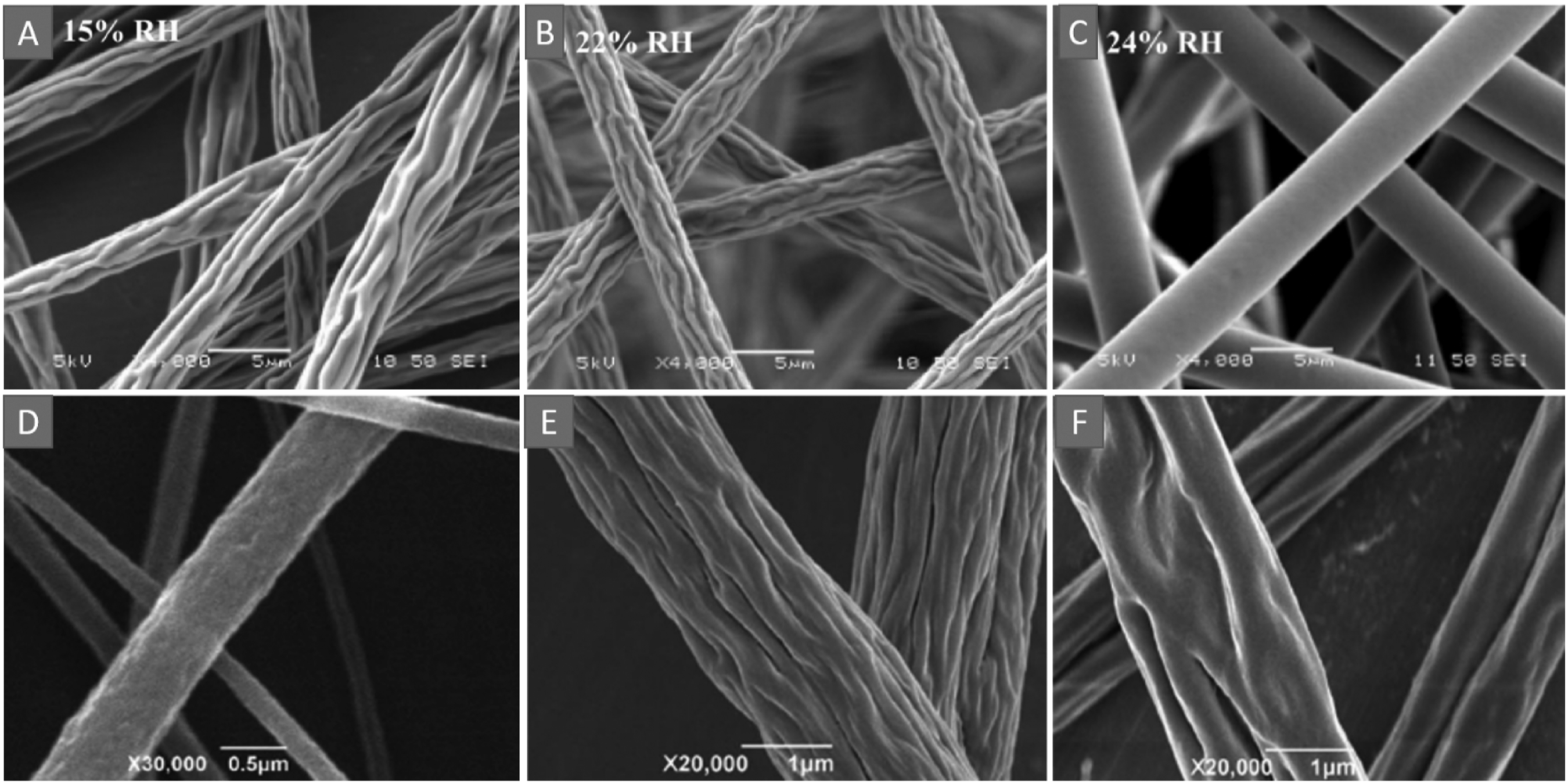
Li et al. produced PMMA wrinkled nanofibers from PMMA/DMF, PMMA/tetrahydrofuran (THF), and PMMA/acetone (ACE) solutions via one-step electrospinning (Figure 2(D)–(F)). They attributed the formation of wrinkled structures to the spinodal decomposition mechanism which is a phase separation mechanism within the miscibility gap. In other words, it is a mechanism for forming two coexisting phases from one thermodynamic phase based on the quick unmixing of a mixture of solids or liquids. 118
Binary solvent systems mean using a mixture of two different solvents to dissolve the polymer for forming nanofiber webs. Wrinkled nanofibers based on binary solvent systems can be generated using high non-solvent/low boiling point solvents and low boiling point solvents/high boiling point solvents.
Huang et al. electrospun successfully wrinkled PLA nanofibers (Figure 3(A) and (B)). They found that by mixing a water-miscible non-solvent with chloroform, and ethanol (highly volatile solvent), a wrinkled structure is generated. They ascribed these results to the high ethanol volatility resulting in the tendency of polymer jet to quickly create a glassy skin on the surface, and the surface of fibers will be soaked with ethanol vapor. Therefore, it is unlikely that water vapor enters into fibers inside and causes phase separation, proposing that the interior porosity is induced by the mechanism of non-solvent-induced phase separation (NIPS).
23

Zaarour et al. generated wrinkled PVDF nanofibers with porous interiors from PVDF/THF/DMF solutions at the solvent ratio of 1/1. They ascribed the formation mechanism of the wrinkled structure to the wrinkle-based elongation mechanism. Herein, a glassy layer on the surface of the jet was formed at the beginning of the electrospinning process owing to the high evaporation rate of a highly volatile solvent (THF) and phase separation. After that, buckling of a cylindrical polymer shell occurs because of solvent elimination from the jets’ core resulting in forming the wrinkled structure. The formation of interior porosity was attributed to the presence of a low volatile solvent (DMF) that has a lower evaporation rate than water (Figure 3(C)–(E)). 83
Composite method
It is a technique for producing material from two or more component materials. These materials have different physical and/or chemical properties and are combined to form a material with new properties. 178 The introduction of nanoscale components, such as nanosheets, nanotubes, and nanoparticles into polymer solutions offers a wide range of possibilities to produce composite nanofibers.
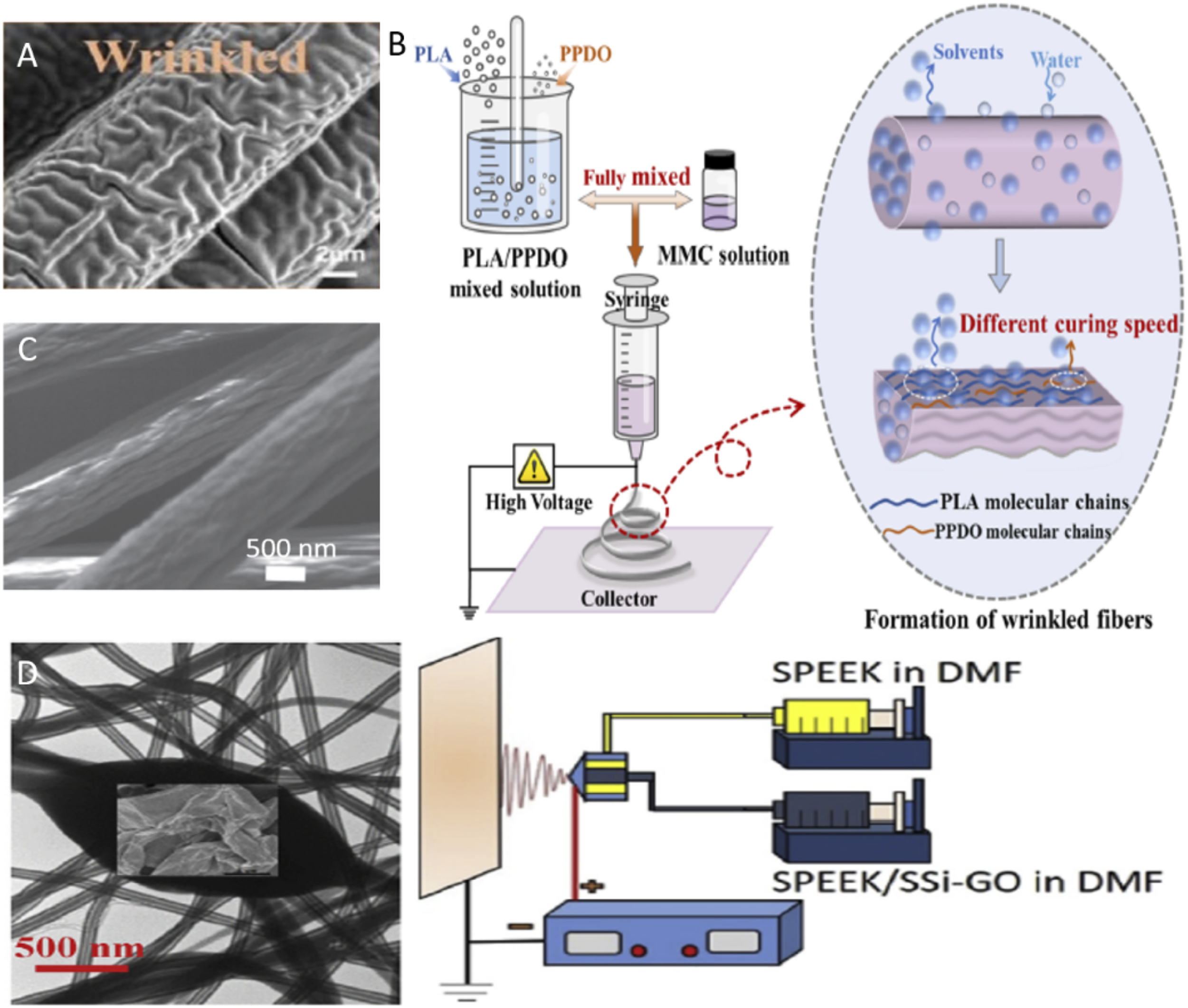
Wang et al. electrospun directly wrinkled PLA/PPDO composite nanofibers after dissolving PLA and PPDO, in dichloromethane. They ascribed the formation mechanism of the wrinkled structure to the phase separation, solvent volatilization, high speed of the polymer jet at high applied voltage, and solidification of the solution in the jet. In other words, these results were attributed to surface buckling instability, curing time, and phase separation (Figure 4(A) and (B)). The fabricated webs showed multiple advantages such as intelligence, porosity, high specific surface area, and favorable for biomedical applications.
119
(A) SEM images of electrospun wrinkled PLA/PPDO fibers.
119
(B) Schematic diagram illustrating the formation mechanism of the wrinkled structure.
119
(C) SEM images of electrospun wrinkled PLA/PPDO fibers TEOS/PAN.
107
(D) Schematic diagram describing the formation mechanism of wrinkled SSi-GO/SPEEK core-shell structure via the coaxial electrospinning.
127
Al-Attabi et al. electrospun successfully wrinkled PAN nanofiber webs from PAN/DMF solution by doping tetraethyl orthosilicate (TEOS) into PAN (Figure 4(C)). They ascribed the formation of wrinkled structure to the presence of TEOS affecting the evaporation rate of DMF and the elasticity of the jet throughout the electrospinning process. In addition, they concluded that the wrinkles’ surfaces increased by increasing the polymer concentration and controlling the ratio of TEOS. 107
Wu et al. fabricated successfully core-shell nanofibers with a wrinkled structure of the core via coaxial electrospinning (Figure 4(D)). The shell was electrospun from the sulfonated PEEK (SPEEk)/DMF solution, whereas the core was electrospun using the SPEEK/sulfonated organosilane functionalized graphene oxide nanosheets (SSi-GO)/DMF solution. They concluded that the inserting of SSi-GOs in the core of electrospun SPEEK nanofibers provides a forced contact between SPEEK and SSi-GOs interfaces resulting in the formation of a wrinkled structure. In addition, the results showed that mechanical and electrochemical properties of electrospun webs can be enhanced by incorporating SSi-GOs. 127
Post-treatment methods
Different post-treatments have been used to form electrospun wrinkled nanofibers. These methods are thermal-induced phase separation process (TIPS), calcination, atomic layer deposition (ALD), polymerization, heat treatment, impregnation, ultrasonication, and sol-gel synthesis.
TIPS
It is a technique for generating a polymer web by mixing the polymer with a solvent at a high temperature and converting the solution into a solid film after cooling the solution. 179 This method is based on the temperature change to induce the de-mixing of a homogeneous polymer solution, thus creating a multi-phase system. When the de-mixing of the solution occurs, the homogeneous solution separates into a polymer-rich and a polymer-less phase. The de-mixing can be solid-liquid (usually for binary polymer-solvent mixtures), or liquid-liquid (usually for ternary polymer/solvent/non-solvent mixtures). 180
Xie et al. Obtained PI nanofiber with wrinkled porous structure via electrospinning technique and subsequent TIPS process, employing PAN as a template. First, a composite of poly (amic acid) (PAA)/PAN nanofibers web was electrospun using PAA/PAN/DMF solution. Then, the web was dried and heated up several times to ensure the removal of the residual solvent, and the elimination of PAN which changes the fibers ‘chemical composition and induces molecules to generate fibers with complex folds surfaces resulting in the formation of the wrinkled porous structure’ (Figure 5(A) and (B)). The results showed that the obtained webs have high specific surface area and good mechanical properties.
122
(A) SEM images of electrospun wrinkled PI nanofibers.
122
(B) Schematic diagram illustrating the fabrication process of PI nanofibers with the wrinkled porous structure.
122
(C) TEM image of hollow ZnO–SnO2 nanofibers with wrinkled porous structure.
109
(D) SEM images of wrinkled LMN nanofibers.
112

Calcination
Calcination means subjecting solid materials to high temperatures in the limited supply or absence of oxygen or air to eliminate impurities or volatile substances and/or to incur thermal decomposition. The calcination process normally takes place at temperatures below the melting point of the product materials. 181
Wan et al. fabricated successfully ZnO–SnO2 hollow nanofibers with wrinkled and porous via the electrospinning method and subsequent calcination process (Figure 5(C)). ZnO–SnO2 nanofibers were dissolved in DMF, while PVP was dissolved in ethanol. Then, both solutions were mixed and loaded into a syringe for electrospinning. The electrospun composite nanofibers were put into a tube furnace for calcination at a temperature of 600°C for 5 h. After calcination, the surface of nanofibers appeared with a wrinkled structure, and their diameter decreased because of the decomposition of PVP. The forming of a wrinkled structure was attributed to the collapse of hollow cylindrical nanofibers and PVP decomposition during the calcination. The webs showed high specific surface area, good selectivity, and outstanding stability for ethanol. 109
Guo et al. prepared winkled perovskite-type La0.9Mn0.6Ni0.4O3-δ (LMN) nanofibers through the electrospinning and calcination process in sequence (Figure 5(D)). Herein, LMN and PVP were dissolved in DMF and put into a syringe for electrospinning. The obtained electrospun webs were calcined for 2 h at a temperature of 700°C, resulting in the formation of wrinkled nanofibers with smaller diameters. These results were ascribed to the PVP decomposition throughout the process of calcination. 112
ALD
ALD is a thin-film deposition method based on the sequential use of a gas-phase chemical process; it is a subclass of chemical vapor deposition. The majority of ALD reactions use two chemicals called precursors (also called “reactants”). These precursors react with the surface of a material one at a time in a sequential, self-limiting, manner. A thin film is slowly deposited through repeated exposure to separate precursors. ALD is a key process in fabricating semiconductor devices and part of the set of tools for synthesizing nanomaterials. 182
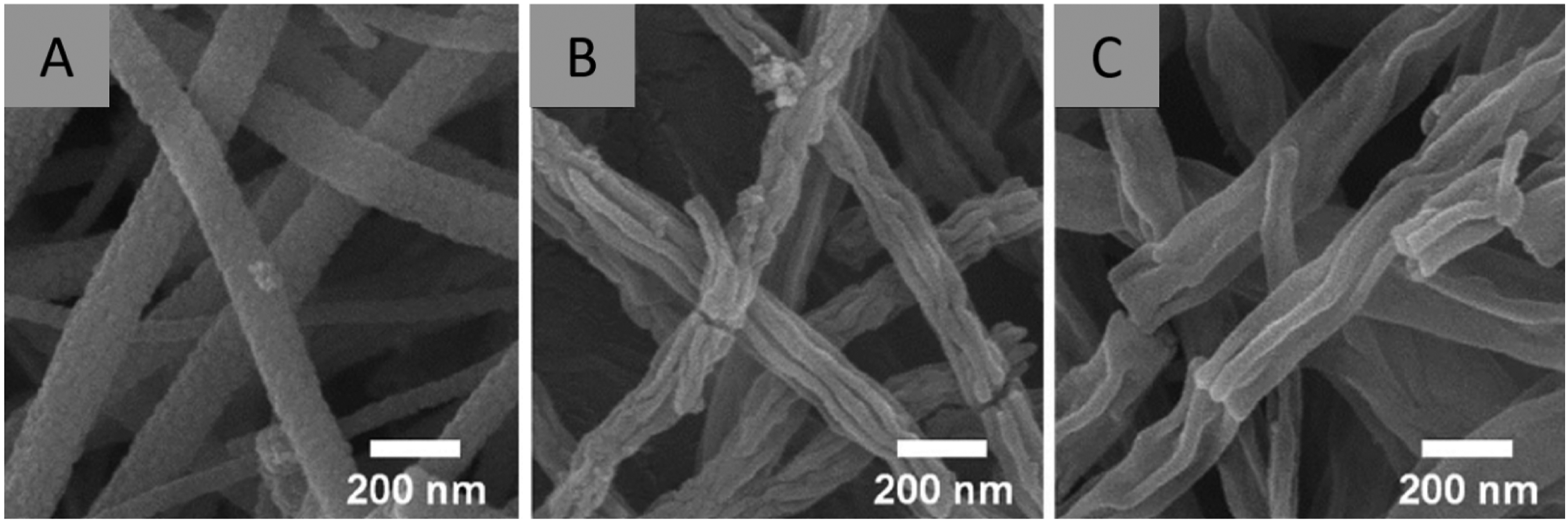
Zhao et al. prepared wrinkled In2O3@ZnO core-shell nanofibers via the electrospinning method and subsequent ALD process. The webs were formed following this procedure: First, PAN/In(NO3)3 nanofibers were electrospun from PAN/DMF/In(NO3)3·4.5H2O solution. Second, ZnO shells were deposited directly on the fibers via the ALD process with controlled cycles. Finally, the nonwoven webs were annealed in the air for 2 h at a temperature of 550°C to get hollow IZO core-shell nanofibers with wrinkled surfaces (Figure 6). These results were ascribed to the ZnO shell shrinkage along with the PAN thermal decomposition.
120
(A) Schematic diagram illustrating the formation processes for pure In2O3 nanofibers as well as hollow and solid core-shell IZO CS nanofibers. SEM and TEM images of (B, C) pure In2O3 nanofibers, (D, E) IZO-50 core-shell nanofibers, and (F, G) IZO-300 core-shell nanofibers.
120

Polymerization
Polymerization means any process that combines monomers chemically to form a network molecule or large chainlike, called a polymer. The molecules of monomers could be similar, or they could represent different compounds. 182
Cao et al. fabricated hybrid wrinkled micro pyramidal PVDF nanofibers via the electrospinning process and polymerization in sequence. The electrospun webs were emerged in ethanol and then homogenized to form a dispersion with a homogenizer. After that, PVDF nanofibers/ethanol dispersion was dip-coated onto the patterned silicon wafer with regularly scattered inverted pyramid microstructures and shifted to a heating plate for heating at a temperature of 100°C to ensure solvent evaporating. Secondly, coated silicone rubber precursor was spun onto the wafer at 500 rpm. It was heated for 30 min at a temperature of 80°C to form a thin film. The Ecoflex film with electrospun PVDF nanofibers (EP-PVDF)-covered hierarchical microstructures array on both one side and double sides were created. The prepared single-side of EP-PVDF nanofibers film with microstructures array was peeled off carefully. After that, another film with the hierarchical microstructures array was spun-coat from Ecoflex in the same condition using the silicon wafer. Then, the single-side EP-PVDF nanofibers thin film was added to the Ecoflex with wafer top and heated for 0 min at 80°C for thermal polymerization. As a final point, the Ecoflex films with PVDF nanofibers-covered hierarchical microstructures array on both sides were peeled off and fabricated successfully (Figure 7).
124
(A) Schematic diagram illustrating the fabrication steps of the double-side EPS-PVDF nanofibers device. (B–D) SEM images of PVDF nanofibers from different sides at different resolutions.
124

Lv et al. fabricated a composite wrinkled nanofiltration web via electrospinning and interfacial polymerization in sequence. The electrospun web was prepared from the PAN solution. After that, the web was coated with polydopamine/polyethyleneimine, which further prompted the mineralization of the web surface with zirconia coatings via hydrolysis of zirconium ions. The abundant zirconia particles acted as templates for providing the polyamide (PA) layer with a wrinkled structure. Finally, interfacial polymerization between trimethyl chloride (TMC) and piperazine hexahydrate (PIP) was conducted on the mineralized web to create a wrinkled PA selective layer (Figure 8). In addition, the wrinkles degree of nanofibers increased with decreasing the thickness of the PA layer owing to the enhanced surface with much hydrophilic support resulting in more storage of aqueous solutions and controlling the constant release of piperazine hexahydrate to the interfacial reactive zone.
121
(A) Schematic diagram illustrating the production process of the composite nanofibers webs with mineralized nanofibers supports. (B–D) SEM images of composite nanofibers webs and their cross-section prepared via interfacial polymerization.
121

Heat treatment
Heat treatment involves the use of heating, normally to extreme temperatures, to achieve the desired result such as hardening or softening of materials. Heat treatment techniques include annealing, case hardening, precipitation strengthening, tempering, carburizing, normalizing, and quenching. It is used to alter the physical, and sometimes chemical, properties of materials. 183
Kwon et al. produced LiFePO4/carbon ((LFP)/C) nanofibers via electrospinning and heat treatment in sequence. The electrospun nanofibers were produced from PAN/LFP/DMF solutions. After that, stabilization of the electrospun nanofibers occurred after stabilizing for 6 h at 100°C in an air atmosphere. The stabilized nanofibers were heated up at 700°C for 3 h at a heating rate of 5°C min−1 in a nitrogen gas atmosphere, resulting in the formation of LFP/C nanofibers (Figure 9). They ascribed these results to the carbonization of PAN due to the heat treatment. These webs showed a high specific surface area and high stretchability.
111
(A) Schematic diagram illustrating the formation steps of the LFP/C NF as cathodes, (B) SEM image of electrospun PAN/LFP composite nanofibers. (C) SEM image of LFP/C nanofibers formed via heat treatment.
111

De France et al. demonstrated the fabrication of wrinkled nanocomposite POEGMA/cellulose nanocrystal (CNC) hydrogel webs via electrospinning subsequent with thermal treatment. The electrospun fibers were electrospun from poly (ethylene oxide) (PEO)/POEGMA/CNC solution. PEO was added to provide appropriate entanglement of the polymer chain. For thermal treatment, PS substrate was used after coating with a base layer of hydrogel with the same components of the nanofibers. Herein, the coated substrates were placed on the collector and POEGMA-CNC hydrogel nanofibers were electrospun with the same components of the base layer on the surface. The resulting nanofiber webs were then subjected to thermal treatment for 15 min at 130°C to enhance wrinkle formation (Figure 10). They ascribed the formation mechanism of the wrinkled structure to the presence of CNC that maximizes the fraction of the POEGMA at the interface while still supporting hierarchical interface fabrication.
125
Schematic diagram illustrating the fabrication steps of POEGMA-CNC hydro-gels with the wrinkled structure.
125

Impregnation
It is a technique for the penetration of polymeric liquids, oligomeric, or monomeric into an assembly of fibers. 183 In other words, it is the procedure whereby a certain volume of solution containing the precursor of the active phase is contacted with the solid (support or another active solid phase), which, in a subsequent step, is dried to remove the imbibed solvent. Thus, this method can be used to prepare supported and mixed catalysts. 184
An et al. fabricated wrinkled Nb-doped TiO2 (NTO) nanofibers decorated with nanophase Ru–RuO2 composites by electrospinning subsequent with impregnation methods (Figure 11). The electrospun nanofibers were formed using Niobium (V) ethoxide/titanium (IV) isopropoxide/PVP/acetic acid/DMF solution. Then, they were calcined for 5 h at 500°C in the atmosphere. After that, Ru–RuO2 composites were decorated on different types of NTO nanofibers by an impregnation method. Herein, mM RuCl3.xH2O was used to decorate NTO nanofibers after dispersion in deionized water. After that, NaBH4 was added as a reducing agent to the prepared solution. Finally, the obtained samples were washed in DI water and dried for 3 h at 100°C. As a result, Ru–RuO2 composites decorating M Nb-doped TiO2 wrinkled nanofibers were successfully prepared. The formation mechanism of the wrinkled structure was ascribed to two reasons: (1) the accumulation of Ti precursors and Nb precursors linked by PVP spun nanofibers; (2) the buckling influence of a cylindrical polymer shell, arising from solvent removal during the electrospinning procedure.
123
SEM images of different wrinkled NTO nanofibers decorated with nanophase Ru–RuO2 composites.
123
Ultrasonication
Sonication is defined as the process in which sound waves are used to agitate the particles in the solutions. Ultrasonication technique is the application of sound energy to chemical and physical systems. Ultrasound generates its effects generally via cavitation, which can introduce many effects such as microjets, shock waves, and intense shear forces, and produces localized hot spots with very high pressures, temperatures, and cooling/heating rates.185,186
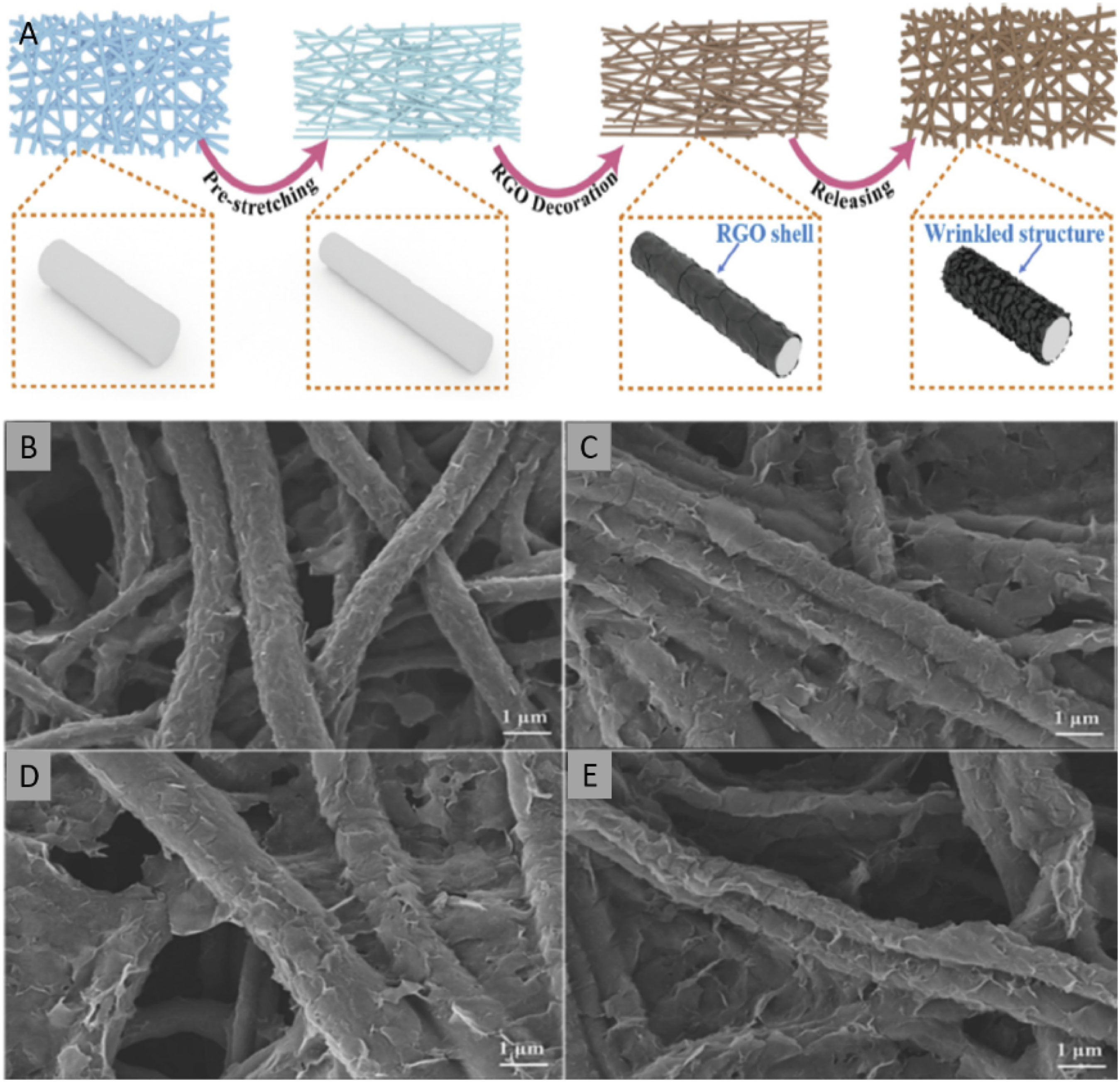
Xiao et al. invented a simple and cost-effective technique to produce flexible nanofiber composites with a polymer nanofiber core and wrinkled reduced graphene oxide (RGO) shell (Figure 12). The process can be concluded as follows: (1) the electrospun PU nanofibers web was uniaxial stretched and fixed. (2) The pre-stretched PU web was dipped in the RGO/ethanol suspension and subjected to ultrasonication treatment to obtain PU/RGO nanofibers composite. The robust interface collision produced during the ultrasonication process incompletely melts the nanofibers, and the RGO was assembled on the surface of the nanofibers by the strong shock wave to form the core/shell structure. Finally, the stretched PU/RGO was released, while the RGO shell was shrunk and stacked disjointedly on the surface of the nanofibers, resulting in the formation of a wrinkled structure. The obtained webs showed excellent flexibility and stretchability.
128
(A) Schematic diagram illustrating the fabrication of the wrinkled nanofibers. (B–E) SEM images of the wrinkled nanofibers obtained at different pre-strain. (B) 0%; (C) 25%; (D) 50%; (E) 100%.
128
Sol-gel synthesis
Sol-gel techniques comprise the transformation from a colloidal suspension containing the glass precursors into a solid network. It is a wet chemical process for the production of different nanostructures including ultra-fine powders, thin films, ceramics and monolithic glasses, and inorganic membranes. 187 In this technique, the molecular precursor is dissolved and converted to gel via heating and stirring. Since the gel obtained is damp, it should be dried using suitable techniques depending on the desired application and properties of the gel.188,189
Park et al. reported the generation of wrinkled nanofibers via electrospinning and sol-gel techniques subsequently. The crosslinked electrospun PVA nanofibers were immersed in alternating solutions of titanium tetraisopropoxide/isopropyl alcohol (TTIP/IPA) and water several times. TTIP hydrolysis and condensation formed stiff TiO2 nanoparticles, which nucleated from the lower modulus PVA surface. The swelling and deswelling of TiO2-coated PVA resulted in generating aligned wrinkles which were enhanced by increasing the cycles of sol-gel synthesis (Figure 13).
190
(A) Schematic diagram illustrating the synthesis of TiO2 sol-gel on electrospun PVA nanofibers. (B–D) SEM images of electrospun wrinkled PVA/TiO2 nanofibers after 1, 3, and 5 cycles of sol-gel synthesis, respectively.
190

Applications
Since the wrinkled structure of nanofibers has outstanding properties such as outstanding specific surface area, good piezoelectricity, coarse surface, high surface energy, excellent biological properties, and the simplicity of forming from a variety of methods and materials, they have attracted much attention for use in different applications such as air filtration, water filtration, gas sensor, energy harvesting, biomedical applications, and energy storage. Herein, different applications of wrinkled nanofibers are reviewed.
Air filtration
Air filtration is a procedure used extensively to filter an air stream from particles. 191 Air filter is a device composed of fibrous, or porous materials that removes solid particulates such as dust, pollen, mold, and bacteria from the air. 192 Filters containing an adsorbent or catalyst such as charcoal (carbon) may also remove odors and gaseous pollutants such as volatile organic compounds or ozone. Air filters are used in applications where air quality is important, notably in building ventilation systems and in engines. 192 Nanofibrous filters with a wrinkled structure have shown great potential in this field thanks to their high flexibility, outstanding specific surface area, exceptional filtration capacity, and high roughness.
Al-Attabi et al. found that the wrinkled structure of the PAN/TEOS nanofibers web can enhance the performance of air filtration compared with the smooth nanofibers web owing to enlarged hierarchal areas and increased stagnancy places. In addition, the quality factor of electrospun fibers with wrinkled structure was better than the benchmarked commercial air web (Figure 14(A)–(C)). These membranes can be used to remove pathogens, gas pollutants, and particles from air.
107

Xie et al. investigated the importance of wrinkled porous in air filtration. The results showed that wrinkled porous PI nanofibers web has an outstanding efficiency of PM0.3 removal (99.99%) with a low-pressure drop at room temperature (43.35 Pa). Furthermore, the filter showed high efficiency (∼95.55%) even at a high temperature of 280°C. Interestingly, they showed high specific surface area and high durability. These results were ascribed to the wrinkled structure which can control the PMs Brownian motion and enhance the effect of mechanical interception to detain the particulate matter on the filter surface (Figure 14(D)). 122
Water filtration
Water filtration is the process in which solid particles in a liquid fluid are removed by the use of a filter that allows the fluid to pass through while retaining the solid particles. Water pollutants (e.g. oil, non-metallic nanoparticles, metal oxides, and heavy metals) are considered a major hazard to the creatures in general. 193 Water filtration can remove or reduce the concentration of suspended particles, parasites, bacteria, algae, viruses, fungi, and more chemical and biological contaminants. This pollution is because of human activity such as offshore platforms, releasing oil to oceans or coastal waters from wells, drilling rigs, and tankers. 194 Nanofiltration is used wildly for water filtration since it shows high flux rates, low energy, high specific surface area, chemical activity, and excellent morphology. 195 Therefore, wrinkled nanofibers are in unlimited demand for scientific researchers fascinated in the water filtration field.
Bandegi et al. fabricated wrinkled SAN nanofiber sorbents for oil-water separation. The sorbents showed high hydrophobicity, uptake capacity, rate of uptake, buoyancy, and outstanding oil sorption capacity of ∼170 g/g (Figure 15). They ascribed these results to the wrinkled structure of nanofibers which enhance oil absorption by physical trapping on the surface of fibers and filling the voids in the sorbent. In addition, the sorbent showed good mechanical properties.
108
(A–C) Oil sorption capacity, mechanical properties, hydrophobicity of electrospun SAN nanofibers webs. (D) Performances of the electrospun PAN/a zirconia mineral nanofibers filter for different salt solutions.
108
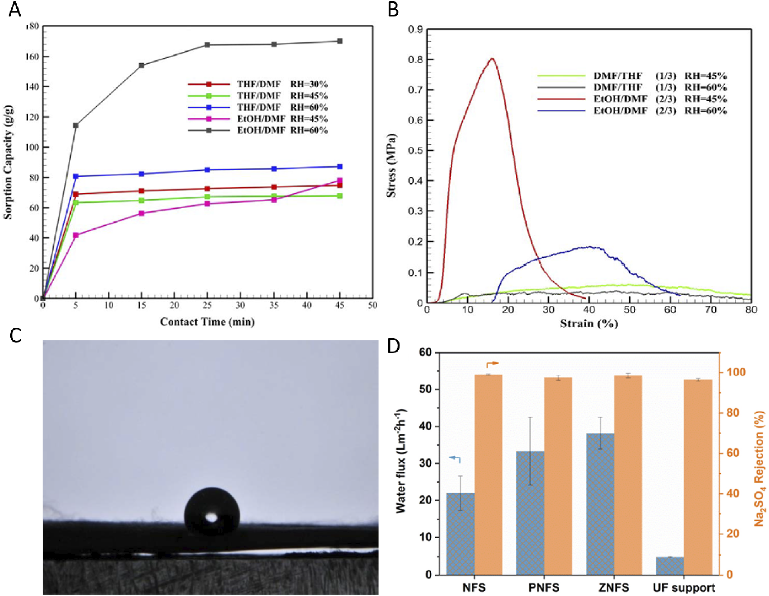
Lv et al. studied the effect of the wrinkled structure of electrospun PAN/a zirconia mineral nanofibers web. The obtained webs showed outstanding efficiency in the filtration area, where the web showed an extraordinary water flux under 4 bar (∼38.2 L m−2 h−1) accompanied by exceptional rejection rate for cations (e.g. 92.4% for Mg2+) and divalent anions (e.g. 97.6% for SO42−). These results were ascribed to the effect of the wrinkled structure which supports the surface bearing opposite charges. 121
Gas sensor
Gas sensor is a system that senses the presence or concentration of gases in the atmosphere. 196 By changing the resistance of the material within the sensor in response to the gas concentration, the sensor generates a corresponding potential difference, which can be calculated as output voltage. Due to its numerous uses in a variety of disciplines, including environmental monitoring, medicine, and industrial process monitoring, gas sensors have garnered considerable interest. 197 In the last two decades, these sensors have attracted the attention of researchers for their applied applications in medical diagnosis, air-quality controlling and monitoring, and flammable and toxic gas detection. 198 Nanofibrous gas sensors are the most favorable sensors owing to their distinctive carrier transport properties, excellent sensitivities, high specific surface area, and outstanding aspect ratio. 199 Consequently, wrinkled nanofibers have served successfully in the field of gas sensors.
Wan et al. found that hollow ZnO–SnO2 nanofibers with a wrinkled porous structure have outstanding gas-sensing properties. The sensor showed greatly enhanced ethanol sensing properties at 260°C. Moreover, it exhibited high stability and excellent selectivity for ethanol (Figure 16(A)–(D)). These results were attributed to the unique wrinkled porous structure of hollow nanofibers which induce the high specific surface area.
109
(A–D) Selectivity, dependence of response on operating temperature, response–recovery characteristics, and stability of the ZnO–SnO2 sensor, respectively.
109
(E) Schematic diagram illustrating the gas-sensing mechanism of the wrinkled In2O3@ZnO sensor.
120
(F) Performance of In2O3@ZnO sensor for sensing ethanol at different temperatures.
120
(G) Responses of In2O3@ZnO sensor toward ethanol at different concentrations.
120
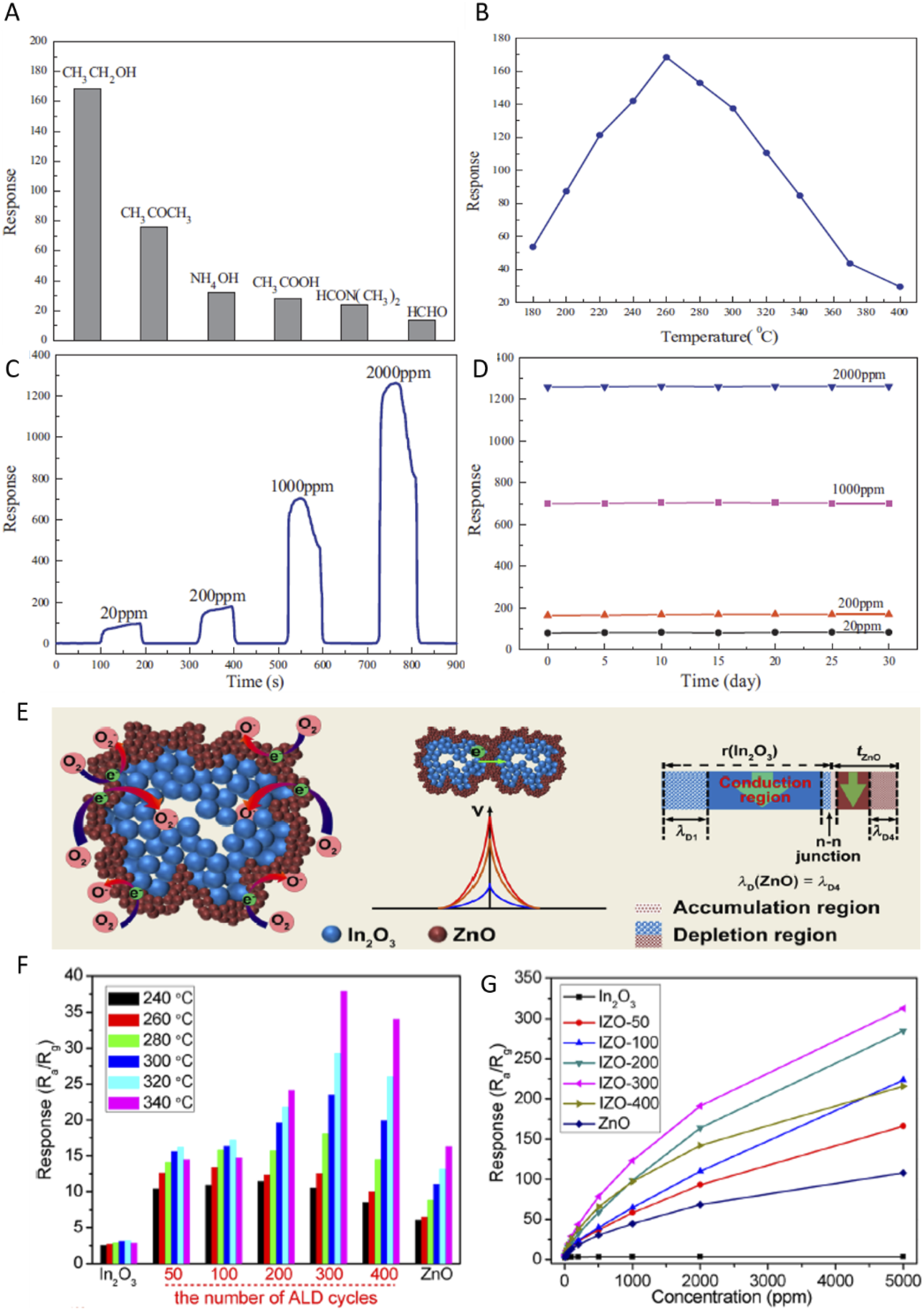
Zhao et al. concluded that wrinkled In2O3@ZnO core-shell nanofibers can enhance the properties of gas sensing for different gases (ethanol and NO2) (Figure 16(E)–(G)). The performance of the sensor was ascribed to the presence of the wrinkled structure which improved the formation of In2O3−ZnO n−n junctions. 120
Energy harvesting
Energy harvesting (power harvesting or energy scavenging) is a process of capturing, collecting, and storing small levels of power in the range of nW-mW scavenged from different sources such as vibrations, mechanical load, light, and temperature gradients.200,201 Depending on the form of energy conversion, nanogenerators can be classified as piezoelectric nanogenerators, triboelectric nanogenerators, or pyroelectric nanogenerators.202–204 Energy harvesters based on nanofibers have been used widely owing to their exceptional properties represented by portability, comfortableness, high specific surface area, high stretchability and flexibility, and excellent shape adaptability. 205 Nanofibers with wrinkled structures have been shown great potential by researchers in the field of energy harvesters owing to their outstanding piezoelectricity and high roughness.
Cao et al. reported the fabrication of skin-like, stretchable, and simple triboelectric nanogenerators based on single-electrode of wrinkled PVDF nanofibers. The sensor showed outstanding strain and tactile sensing performance as well as high durability. The sensitivity of the measured tactile response of the sensor was about 20.1 V/N, and the output voltage was ∼4.3 times higher than the unmodified sensor (Figure 17(A)–(E)). These results were ascribed to the high dielectric constant of the wrinkled PVDF nanofibers and the enhancement of friction factor and the contact area.
124

Fang et al. designed a high-performance and flexible piezoresistive sensor based on PEDOT coated wrinkled PVDF-HFP nanofibers web. The sensor displayed an ultra-high sensitivity (∼397.54 kPa−1) in both an ultra-wide pressure range (∼0–25.48 kPa) and a small pressure range (∼0–3 kPa). In addition, it showed high durability even after 16,500 compression cycles. These results were attributed to the presence of the wrinkled structure which enhanced stretchability, flexibility, and the specific surface area of the active layer under the pressure. 126
Xiao et al. produced a flexible nanofiber composite sensor with a PU core and wrinkled RGO for sensing the strain and temperature. They showed high strain sensing sensitivity (up to 154.8 gauge factor in the 85%–100% strain range). In addition, it showed excellent stability even at 1000 cycles resulting in its ability to serve successfully in body motion monitoring. Furthermore, it possessed high hydrophobicity and excellent performance for photo-thermal conversion. Moreover, it showed a negative effect on temperature coefficient and can be served for high-performance temperature sensors. These results were attributed to the presence of wrinkled and conductive RGO shell which improves the hydrophobicity, friction factor, and specific surface area. 128
Zaarour et al. investigated the effect of the surface morphology on the electrical outputs of the piezoelectric nanogenerators. They found that the PENG based on wrinkled PVDF nanofibers exhibited outstanding electrical outputs (4 μA and 2.8 V) compared with smooth and porous structures which are enough to run a temperature and humidity sensor using an electrical circuit Figure 17(F) and (G). These results were attributed to the wrinkled surfaces of nanofibers, high F (β), and the small air gaps between aligned nanofiber webs. 106
Energy storage
Energy storage is the capture of energy produced at one time for use at a later time to reduce imbalances between energy demand and energy production. A device that stores energy is generally called an accumulator or battery. Energy comes in multiple forms including radiation, chemical, gravitational potential, electrical potential, electricity, elevated temperature, latent heat, and kinetic. Energy storage involves converting energy from forms that are difficult to store to more conveniently or economically storable forms.206,207 Energy storage devices such as batteries and electrochemical capacitors are presently of great interest due to the rapid improvement of electronic devices such as flashlights, electric vehicles, mobile phones, and laptops. 208 Electrochemical capacitors have outstanding properties such as long cycle life, high rate capability, and high power density. 209 Importantly, since wrinkled nanofibers have high porosity and large surface areas, they have been used successfully in the field of energy storage.
Kwon et al. designed an exceptional stretchable lithium full-cell battery using 1D nanofiber active materials, wrinkle structure electrodes, and stretchable gel polymer electrolyte. A LiFePO4/C nanofibers cathode and SnO2/C nanofiber anode introduce micro- and mesopores for electrolyte penetration and lithium-ion diffusion.
The full cell consists of PDMS wrapping film, LiFePO4/C, and SnO2/C nanofiber electrodes with a wrinkle structure placed on the PDMS film by an adhesive polymer, and a gel polymer electrolyte. It showed extraordinary discharge capacities of 128.3 mAh g−1 in the stretched state and 138.6 mAh g−1 in the released state which could be accomplished for the high energy density stretchable battery (∼458.8 Wh kg−1) (Figure 18).
111
(A) Schematic of the stretchable full-cell battery in stretched (30% strain) and released states, (B) the voltage output of the full-cell battery, (C, D) The performance of stretchable full cell in its released and stretched states, respectively., (E) profile of charge-discharge, and (F) the full-cell battery cycling performance in stretched and released states.
111

Guo et al. synthesized wrinkled LMN nanofibers as cathode catalysts for Li-O2 batteries. They found that the batteries based on the LMN nanofibers catalyst have an outstanding specific discharge capacity of 9397 mAhg−1, high cycle stability of ∼100 cycles, and low voltage gap of 1.111 V at a 300 mAg−1current density (Figure 19). These results were ascribed wrinkled structure of nanofibers that provides sufficient provision and abundant active sites for Li2O2 deposition.
112
(A) Cyclic voltammetry of LMN nanofibers and LMN nanoparticles, (B) capacity comparison of (C) LMN nanofibers, and (D) LMN nanoparticles in the full charge/discharge curves of Li-O2 batteries.
112

An et al. produced wrinkled Nb-doped TiO2 (NTO) nanofibers decorated with nanophase Ru–RuO2 as a support for electrochemical capacitors. Their product showed superior capacitance of ∼496.3 F/g at 5 mV/s and outstanding high-rate capacitance thanks to the wrinkled structure of nanofibers which enhance the specific surface area as well as the existence of the nanophase Ru–RuO2 composites. 123
Biomedical applications
Nanofibers have been used widely in biomedical applications such as bioscaffolds, tissue engineering, drug release, and drug delivery thanks to their pore size adjustability, high porosity, and specific surface areas. 210 Therefore, the wrinkled structure has been serving successfully in the field of biomedical applications.
Golchin et al. electrospun wrinkled nanofibrous scaffold from PVA, CS, polycaprolactone, carbopol, Cur, and buccal fat pad derived mesenchymal stem cells (BFP‐MSCs) using a dual electrospinning method for drug delivery and regenerative medicine. The scaffold showed suitable biological support properties, including protein and water adsorption resulting in better cell adhesion, growth, and viability rate for the duration of study. In addition, it exhibited a suitable Cur release for 2 weeks (Figure 20). These results were attributed to the wrinkled structure which enhances contact areas and sensing.
110

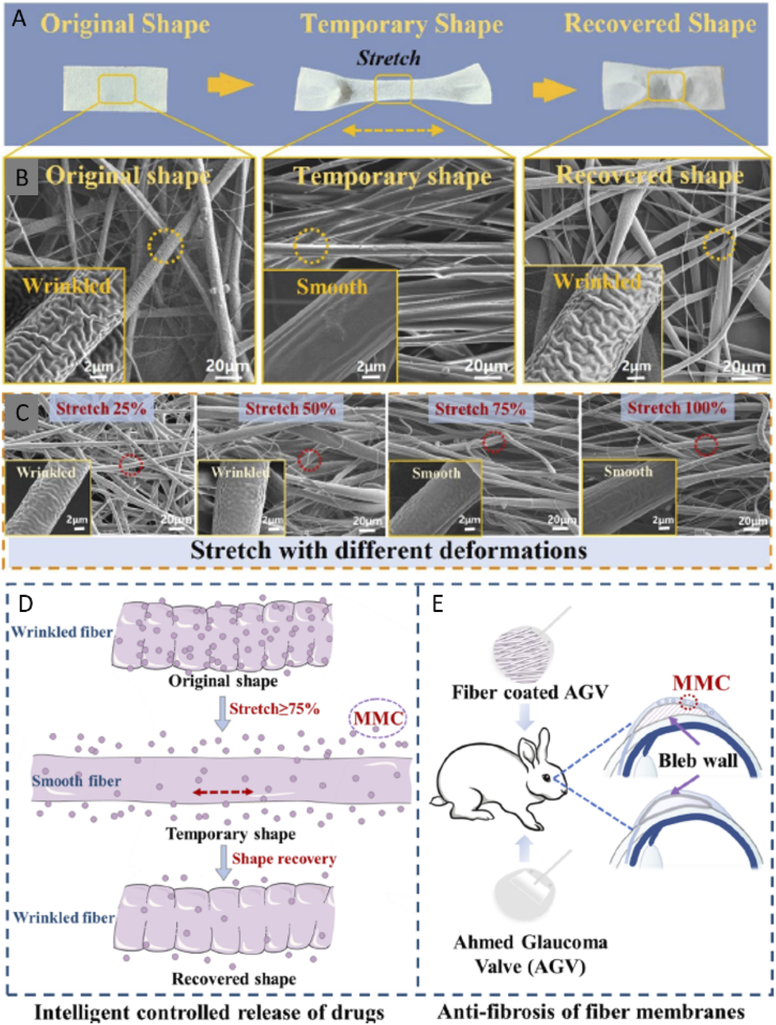
Wang et al. fabricated shape memory PPDO/PLA composite nanofibers for anti-scarring and drug release applications. The shape memory was designed at a transformation temperature of 41.3°C which is close to body temperature. The stretched and deformed drug-loaded fiber webs showed faster drug release compared with the original shape. The oriented fibers can prevent tissue growth, thus decreasing the scarring formation. As a result, the PLA/PPDO web can be used to relieve the scarring while regulating the drug release intelligently (Figure 21).
119
(A–C) Performance test of PLA/PPDO shape memory fiber webs. (A) Real images of stretched fiber web; (B) SEM images of stretched fiber web; (C) SEM images of stretched fiber web at different tensile deformation. (D, E) schematic diagram describing smart controlled drugs release, and the effect of anti-scarring fiber webs, respectively.
119
De France et al. formed wrinkled nanocomposite POEGMA/CNC nanocrystal hydrogel webs in cell screening. The surface structures of oriented hydrogel mainly affected cell alignment, with cells showing a more random orientation on biaxially wrinkled hydrogels but specially orienting and extending along the wrinkles in uniaxially wrinkled hydrogels. 125
Fuel cells
A fuel cell is an electrochemical cell that converts the chemical energy of a fuel (often hydrogen) and an oxidizing agent (often oxygen) into electricity through a pair of redox reactions. In other words, A fuel cell is any device that generates electricity directly from the fuel chemical energy converting based on electrochemical reactions. 211 Fuel cells are different from most batteries in requiring a continuous source of fuel and oxygen (usually from air) to sustain the chemical reaction, whereas in a battery the chemical energy usually comes from substances that are already present in the battery. Fuel cells can produce electricity continuously for as long as fuel and oxygen are supplied. 206 Since the electrospun nanofibers have unique structure, ion and electron conduction properties, and high specific surface area, they have been used perfectly as electrodes resulting in enhancing the electrochemical performance of the fuel cell. 37 Herein, the efficiency of the wrinkled nanofibers in fuel cell applications is reviewed.
Wu et al. investigated the configuration of the functionalized GO in SPEEK nanofibers to achieve better compatibility of organics and inorganics, and thus realize both decreased fuel-blocking effect and improved proton conductivity. The wrinkled GO contains the micro-voids the sulfonated functional groups enhanced the web water uptake and thus improved hydrogen bond network formation for proton hopping as well as tortuous pathways for fuel barrier (Figure 22). Accordingly, both improved conductivity and reduced fuel crossover succeeded.
127
(A) Schematics diagram describing the transport of methanol and proton in SPEEK/SSi-GO core-shell composite web. (B) Water uptake and swelling ratio of the blend cast, mono-spinning, and co-spinning polymer electrolyte web as a function of SSi-GOs contents. (C, D) Proton conductivity of the blend cast, mono-spinning, and co-spinning polymer electrolyte web (C) as a function of SSi-GOs contents and (D) with an SSi-GOs content of 2.5 wt% as a function of temperature.
127

All the reviewed applications have been summarized in Table 1.
Summary and future outlook
This study reviews the materials, preparation methods, and applications of the electrospun wrinkled nanofibers. The electrospinning technique, materials, production methods, strategies, and applications of the electrospun wrinkled nanofibers are discussed comprehensively. According to our review, it can be concluded that: 1. Wrinkled nanofibers can be electrospun from different materials such as PAN, PI, PS, PVDF, PVDF-HFP, PVP, POEGMA, SAN, PEEK, PVA, PCL, PU, PPDO, PLA, CS, ZnO–SnO2, and LMN. 2. Electrospun wrinkled nanofibers can be formed either directly (solvent systems and composite methods) or by post-processing (TIPS, calcination, ALD, polymerization, heat treatment, impregnation, ultrasonication, and sol–gel synthesis). 3. Electrospun wrinkled nanofibers have exceptional properties (e.g. high specific surface area, good biological properties, excellent piezoelectricity, high roughness, and good piezoelectric properties). 4. Wrinkled nanofibers can be used successfully in different fields according to the type of materials (e.g. air filtration, water filtration, energy harvesting, energy storage, gas sensor, fuel cell, and biomedical applications).
In recent years, the wrinkled structure has shown magnificent attainments in technological improvements and fundamental understanding. Regarding the future applications of wrinkled nanofibers, some important points should be addressed: 1. Investigating the relationship between the formation methods and properties of the electrospun wrinkled nanofibers. 2. Studying the effect of the material type on the properties of the electrospun wrinkled nanofibers. 3. Exploring the effect of fillers on the formation of wrinkled nanofibers and enhancing their properties. 4. Exploring the effect of diameter on electrospun wrinkled nanofibers on their properties. 5. Investigating the importance of the wrinkled structure in new applications such as food packaging and self-cleaning surfaces. 6. Investigating the generation of nanofibers with wrinkled structures from new materials.
In summary, many companies have started producing commercial products based on electrospun nanofibers such as RevolutionFibres Ltd, IQ Commercial, Liquidity Corp., BIOTRONIK, MEDPRIN, eSpin Technologies, 3D Biotek, SKE Advanced Therapies. Therefore, nanofibers with the wrinkled structure has the chance to be one of the most favorable demands of commercial companies. We believe that this review will give a comprehensive prospect for the properties and surface structure of wrinkled fibers.
Footnotes
Declaration of conflicting interests
The author(s) declared no potential conflicts of interest with respect to the research, authorship, and/or publication of this article.
Funding
The author(s) received no financial support for the research, authorship, and/or publication of this article.