
Abstract
Nanotechnology, deals with materials on the order of 100 nm, has been showing immense potential for the last four decades. Precise manipulation and stringent control on structure of materials allows nanomaterials to have unique characteristics. The versatility of electrospinning has resulted in the development of techniques such as melt, coaxial, needleless, single and multi-needle, wet, solution and hybrid methods, which produce nanofibers with diverse applications in biomedical engineering, tissue engineering, drug delivery, filtration, protective clothing, and energy systems. Some key factors, like polymer molecular weight, temperature, humidity, electric field strength, and viscoelasticity, are important parameters in electrospinning, and they affect fiber morphology, diameter, and quality. Again, electrospinning faces some barriers like scalability issues, irreproducibility, solvent toxicity, frequent needle clogging, adhesion issues, mechanical inconsistencies, etc. This comprehensive review aims to discuss various methods of electrospinning in relation to nanofiber production. It also discussed a brief history of the development of electrospinning. Again, it covers the effect of factors on the properties and morphology of electrospun nanofibers. Moreover, this review illustrates merits, and drawbacks of producing nanofibers through electrospinning. Although there are several solutions in practice to mitigate some of the limitations, but there are room for further research. Lastly, it covers the current and potential utilization of electrospun nanofibers.
Introduction
Electrospinning is a practical, most crucial and adaptable method for producing ultra-thin fibers that are widely used in medical, membrane, composite materials, filtering, and other industries. 1 This versatile, simple and inexpensive process applies high voltage, at least 6 kV, between a metallic collector and the tip of a needle to produce nanofibers with some exception. 2 To produce micro and nanofibers via electrospinning, a polymer solution, a high-voltage power source, a syringe pump, a syringe, a needle, and a collector are needed. The typical arrangement for electrospinning equipment is either vertical or horizontal.3–5 Figure 1(a) and (b) depicts a schematic arrangement of vertical and horizontal of electrospinning process. 6

Schematic of the electrospinning device’s layout, which includes both a) vertical and b) horizontal setup using under.
On the other hand, nanotechnology, dealing with materials with one or more dimensions of the order of 100 nm, enables precise manipulation of materials at atomic, molecular, and super molecular levels, has been improving for over 40 years. It is capable to impose extraordinary control over material properties and structure at the nanoscale and develop functional systems with unique physical, chemical, and biological properties.2,6,8–10
The field of polymeric nanofibers has experienced a dramatic growth during the last few decades. High aspect ratio, large surface area to volume, multifarious applicability and manufacturability are the main drivers behind these popularity. 3 Polymers with a high sub-atomic degree are constantly utilized as unrefined components in light of their intermolecular communications.1,4
Electrospinning, very adaptable and able to obtain specific properties through structural, chemical, physical, and biological modifications, is the most notable technology to create various kinds of polymeric nanofibers modifying the spinning system or processing parameters. For instance, during the COVID-19 pandemic, disposable sanitary products were produced in bulk using industry-scale electrospinning. 6 Nanofiber-based products has massive applications in the fields of public health, medicals, sensors, catalysis, wearables, air/water filtration, and energy storage.2,6,8,9,11 There are multiple types of electrospinning techniques. Each of these has its own characteristics, merit and suitability to produce different nanofibers. 7
The aim of this review is to showcase various methods of electrospinning that produces a wide range of nanofibers; emphasizing on the processing parameters and determining factors and their effect on nanofibers properties and morphology. It also provides a brief history, account of the merits and challenges of producing electrospun nanofibers. Moreover, it gives an account of the current utilization of electrospun nanofibers. Lastly, it discusses on the future trends of electrospinning nanofibers underscoring the research direction for the same.
History of electrospinning
Sir William Gilbert clarified the behavior of magnetic and electrostatic emissions at the end of the 15th century. He found that a water droplet assumes the shape of a cone and hopper when an electrostatic field is given to it, and a droplet emerges from the hopper’s head. Thus, the original electro-spraying technique was invented. 1 John F. Cooley was granted a patent for a process known as “Electrospinning” in 1900 for a device that used electricity to separate the comparatively volatile liquid component of composite materials from the relatively fixed substance component. In 1902, he created an electrically dispersing device, while William James Morton developed techniques for dispersing fluids by breaking down the fixed element in composite fluids and separating the volatile elements . 5 In 1914, John Zeleny treated liquid droplets at the end of iron capillaries and searched for a mathematical description to do this study. In the 1930s, Anton Formhals made an attempt to produce electrospun fibers. 1 In 1934, he successfully generated the process to electrospin polymers. He applied for many patents between 1934 and 1944 that described the experimental design technique of forming polymer strands by electrostatic force. 12 Late in the 1960s, Sir Geoffrey Ingram Taylor created the Taylor cone model, which served as the theoretical foundation for electrospinning. 13 The possibility of electrospinning for fibrous mats at the nanoscale and submicron size was investigated by Simon in the 1980s. In 1988, he suggested electrospinning could produce nanoscale fibrous mats for in vitro cell substrates and noted that fiber surface chemistry varies with electric field polarity. Later, in the 1990s, Reneker and Rutledge confirmed that electrospinning can create nanofibers from various organic polymers. 12 Significant progress was made in electrospinning after the year 2000, and it became popular in many other disciplines, particularly in the 2000s and 2010s. These developments included process improvements, broader applications, and the creation of novel materials and methods. 14 Applications for electrospinning have been found in a variety of fields, including nonwoven materials, medication delivery, tissue engineering, and energy storage. 15 In order to create novel functional materials, researchers investigated the application of electrospinning with a variety of materials, such as polymers, ceramics, and composites. The design of the device, the materials employed, and the nanomaterials created have all seen substantial advancements. 16 The creation of multimaterial electrospinning, which combines many materials to produce intricate fiber structures with superior performance, gained popularity, especially in the biomedical industry. 17 Research activities concentrated on scaling up electrospinning for industrial applications to produce more nanofibers for a variety of uses. 18 Research is still being done to increase electrospinning’s effectiveness and adaptability, investigate new materials, and broaden its range of uses, especially in dentistry. 19 Figure 2 shows a brief history of electrospinning. 20
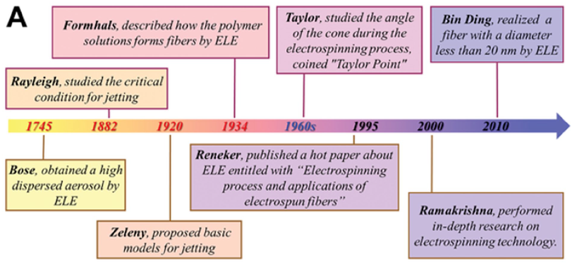
A brief history of electrospinning. 20
Methods of electrospinning and its impact on nanofiber
Different nanofiber electrospinning techniques are generally available to meet the unique needs of various sectors and technology. A list of most significant electrospinning methods are shown in Table 1.17,21–29

Melt electrospinning
Melt electrospinning, a combination of melt blowing and electrospinning, makes it possible to produce fibers with a variety of diameter distributions in a single operation. 30 It involves forcing a polymer melt through a syringe pump or other devices and includes air pressure systems, screw extruders, or mechanical feeds. The most widely used initiation technologies are gas-assisted, laser-based, needle, and needleless.
Temperature, applied voltage, device height, tip-to-collector distance, spinneret diameter, viscosity, molecular weight, melting point, and flow velocity are the primary variables that impact the melt electrospinning process. Figure 3 depicts the various heating ways of melt electrospinning. 8 The electric field strength has a major impact on nanofiber diameter; as the electric field strength increased, the fiber diameter decreased. However, a strong filed can make the jet unstable and create beads.2,9,31,32 Nanofibers with diameters less than 100 nm can be produced at high voltage (>90 kV) and high rotational speed (up to 500,000 rpm).2,6,8,9 Higher molecular weight polymers form fibers with a smaller diameter than the isotactic one. However, non-crystallizable atactic (non-baseline) polymers produce fibers with a larger diameter even at lower molecular weights. The fiber’s diameter and form are influenced by the viscosity of the polymer solution. In addition to decreasing viscosity, increasing viscosity can also promote the development of thinner fibers.6,31,32 Melting point of polymer is another consideration. Higher temperatures can assist the manufacturing of fiber by reducing the viscosity of the polymer melt led to better crystallinity and smoother fibers.3,6,8,31,32 Differences in melt flow index which determines the form and homogeneity of a fiber lead to variations in the fiber characteristics.3,8,31

Diagrams illustrating the several heating techniques used for melt electrospinning. 8
Single needle electrospinning
Modern Single needle electrospinning systems, either horizontal or vertical, consist of pumps, a high-voltage source of power, a needle, an imaging device, and a device that collects electricity as seen in Figure 4. 25 The power supply’s positive pole is connected to the metal needle, while the negative pole is connected to the collector. The needle’s tip becomes electrically charged as a result of the large voltage difference between the needle and collector. “Taylor cone” gets produced by the charged solution as the pump fills the syringe; causing polymer jets to start emerge from the needle tip and proceed toward the collector. Solvents evaporate in combat, stiffening the jet before it gets to the collector. 33 The consistency of the process is impacted by the irregular electric field while producing nanofiber. Needle-disk systems and flat spinnerets provide more constant electric fields leading to better nanofiber quality. 34

Basic schematic of a single-needle electrospinning setup. 35 Copyright © 2019, Springer Nature Switzerland AG.
The applied voltage and the polymer solution’s flow rate were used to alter the short nanofibers’ lengths. 36 Increased electrostatic pressures at higher voltages (e.g. 12–18 kV) encourage fiber elongation and decrease diameter. The ideal flow rates balance solvent evaporation with fiber production, and they normally fall between 30 and 90 μL/min. 37 Thinner fibers without beads were formed at a collector distance of 15 cm, whereas thicker, non-beaded fibers were produced at lesser distances. This is because the final fiber shape is impacted by the jet’s inability to solidify at shorter distances. 35 Raising the polymer solution’s concentration stops beads from forming and produces a thicker, continuous nanofiber shape. 35 Increased viscosity from higher concentrations improves the solution’s intermolecular interactions and encourages the creation of better fibers. 38 Regulated circumstances 44%–50% relative humidity and 24°C–26°C are critical for repeatable fiber morphology outcomes. 38 Hollow and core-shell structures may be created by single needle electrospinning with improving functionality for uses in medication administration. 35 Nanofibers made from a variety of polymers, such as polyvinyl alcohol and polycaprolactone, can be electrospun to provide customized characteristics. 39
Needleless electrospinning
The latest technique for creating nanofibers without the requirement of conventional needle-based spinnerets is called needleless electrospinning. It overcomes the drawbacks of conventional needle electrospinning such as needle clogging and limited throughput. An electric field created by applying a high voltage (12 and 18 kV) to a polymer solution during the electrospinning process pushes the solution into a jet that cools to produce nanofibers. Owing to its potential for large-scale manufacturing, this approach has drawn a lot of interest especially like China, Australia, and the Czech Republic. 25 Figure 5 shows various motionless spinneret designs. Spinneret designs with higher electric field intensity at the edges, such as the toothed wheel and sprocket wheel disk, create more homogeneous nanofibers with lower diameters. 40 Aerodynamic and electric fields can increase production rates by up to 350% without appreciably changing fiber diameter. 41

Schematic summary of needle-less motionless spinnerets. 25
Parameters include the distance between the tip and collector, the voltage applied, polymer solution’s concentration, the flow rate, and air filtration efficacy. 42 Fiber stretching can be improved and diameter can be decreased with higher voltages. 43 Lou et al. studied needless electrospinning of water-soluble chitosan (WS-CS) and found that the diameter of the nanofibers was found to decrease as the WS-CS concentration rose. For example, at greater WS-CS concentrations, the lowest fiber diameter measured was 216.58 ± 58.15 nm. 44 Finer fibers may result from a lower flow rate and vice versa. This relationship is essential for tailoring the properties of the nanofibers for specific applications. 43 The polymer jet may stretch and solidify more efficiently with a greater distance between the tip and collector, which frequently produces finer fibers and vice versa. 45 Fiber development depends on relative humidity as well; at polyethylene oxide (PEO) concentrations of 3, fiber creation takes place at 46% humidity, but at PEO concentrations of 5, it begins at 52% and rises with decreasing humidity levels. 46 Ramakrishnan et al. studied effect of solution properties and operating parameters on needleless electrospinning of PEO nanofibers loaded with bovine serum albumin (BSA) and produced nanofiber of 100–150 nm size. The result showed that the air filtration efficacy of the nanofiber mats is improved by raising the solution temperature from 20°C to 60°C, which produces finer fibers and with greater production rates. Also, the results showed the BSA is well encapsulated in the PEO matrix with no changes in the protein structure. 47
Coaxial electrospinning
Coaxial electrospinning, can create hollow, functionalized, core-shell and hollow fibers, is used to encapsulate growth hormones, DNA, and even living things. These agents are shielded from direct interaction with organic solvents and challenging environments by the core-shell nanofibers. 48 Nanofibers with enhanced mechanical, electrical, and chemical properties are produced using coaxial electrospinning, which makes them appropriate for use in the environmental, energy, and biological sciences.49,50 Coaxial electrospinning allows combining materials that are otherwise difficult to process together, such as semiconductive polymers, enabling the creation of novel nanostructures for electronic applications. 51 A schematic of coaxial electrospinning is found in Figure 6. 52

Schematic diagram of the coaxial electrospinning setup for core-shell fiber fabrication. 52
Polymer concentration, viscosity, surface tension, dielectric constant, voltage, Taylor cone, and conductivity are important parameters. 53 Higher voltages result in a better stretched jet, which calls for the production of finer fibers.49,53–55 The angle of the “Taylor cone” is a factor to determine the nanofiber’s diameter. The length of the straight fluid jet is also important. Larger spreading angle gives small final nanofiber, while smaller diameter gives the fast dissolution rates of poorly water soluble drugs and improves the release profiles. 53
High viscous solution is more likely to produce thicker fiber and vice versa. The variation in the rates of solution feeding, secretion and growth can alter the thickness of the shell and the total morphology of the nanofibers. 49 Multilayered fiber’s separate layers can be engineered to have distinct properties, such as electrical conductivity and hydrophilicity. Additionally, the coaxial fibers can be extremely porous and the structures possess sufficient mechanical properties and a high surface-to-volume ratio which are critical for their use as drug delivery systems.49,54–58 Functional performance may be added to the nanofibers using unspinnable fluids. Modified coaxial electrospun nanofibers have shown improved adsorption capabilities for contaminants, and their potential for environmental applications is encouraging. 59
Multineedle electrospinning
Multineedle electrospinning is based on the traditional single-needle electrospinning technique but needs several needles as shown in Figure 7. Using a lot of needles boost the amount of “Taylor cones” and their alignment and arrangement influences the characteristics of the electro spun jets and the final shape of the created fibers. The creation of nanofibers might be greatly increased by splitting the Taylor cones into several jets.60,61 Employing a plastic filter or gas-assisted techniques reduce fiber repulsion, boost throughput, improve fiber uniformity and increase production rates. 62

Schematic illustration of a multi-needle electrospinning setup using spinnerets. 60
The concentration of the polymer, applied voltage, solution conductivity, distance between the spinneret and the collector, fiber velocity, flow rate of the liquid, number and placement of needles, humidity and temperatures are the parameters in this process. Greater concentration leads to higher diameters. Thinner nanofibers are produced when the voltage is increased because it raises the electric field force, which in turn increases the tensile force on the polymer solution. Furthermore, the shape of the collected nanofibers and the drying period of the fibers are both impacted by the distance between the spinneret and the collector. Maintaining a steady fiber velocity is crucial for obtaining uniform fiber sizes. The total productivity and fiber quality of a multi-needle electrospinning system can be influenced by the number and placement of needles. The yield of gas-assisted electrospinning is greatly increased by using a trapezoidal or linear array of a certain number of needles.61,63–65
Higher humidity and lower temperature can create porous and rough surfaces of nanofibers, and the opposite leads to smoother one. The charge distribution and jet stability in the electrospinning process are also a function of solution conductivity.65,66
Electrospinning with auxiliary fields
Electrospinning combined with auxiliary fields can be used to produce nano-sized fibers for use in controlled-porosity structures for tissue engineering, barriers, membranes, fabrics, and garments, as well as to dispense drugs. The utility of the finished structures is reduced by the nozzle tip’s generation of nonwoven fibrous mats as an outcome of jet a whipping and bending instability. The synthesis of aligned fibers has led some scientists to look for ways to enhance jet stream control. Occasionally, scientists have positioned the collector very near the spinneret in an attempt to catch the jet before it becomes unstable. Since the solvent cannot be eliminated prior to collection, aligned ribbons are frequently the outcome, and the largest fiber diameter that may be produced is constrained. An additional electrode is positioned precisely across from the spinneret and 90° to the rotating mandrel as in Figure 8. The voltage that the auxiliary electrode received and the voltage that was delivered to the spinneret were both the same and different. This design, which is often associated with the electrospinning process, removes the bending, and whipping instabilities by creating a regulated electric field. 67 A consistent electric field distribution is achieved with the aid of parallel plate auxiliary electrodes, which is essential for multi-needle electrospinning installations. This homogeneity enhances fiber shape and deposition while lowering “Coulombic repulsion.” 68 Auxiliary fields can cause consistent and smaller fiber diameters by regulating the electric field geometry and stabilizing the jet.69–72

Schematic of a Electrospinning set-up incorporating the auxiliary electrode. 67
Solution electrospinning
The balance between the drug-loaded nanofibers’ mechanical and physicochemical characteristics is improved by the addition of polymeric blends. Additionally, it significantly improves the drug release formulation’s design, making it possible to regulate the release rate by varying the blended solution’s polymer proportion. When using the mixing electrospinning process, drug encapsulation is completed by electrospinning in a single step since the drugs are dissolved or dispersed in the polymeric solution.
Figure 9 represents the solution electrospinning process. 73 The kind of solvent has a big impact on fibers development. For instance, poly(vinylidene fluoride)-co-hexafluoropropylene (PVDF-HFP) may be electrospun from dimethylacetamide (DMAc) at 75°C and acetone at −19°C.74,75 By improving the spinnability of different solvents, active solution heating and cooling can improve electrospinning control and increase the number of solvents that can be used. 74
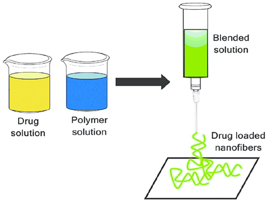
Representation of principle of solution electrospinning. 73 (Using under Creative Commons Attribution 3.0 License).
In solution electrospinning, important parameters include solution ration, concentration, viscosity, surface tension, electric field’s stretching, voltage, tip to collector distance and flow rate. Lower concentrations could produce finer fibers because of improved electrospinning conditions and decreased viscosity.30,76,77 He et al. did an experiment where a higher electroactive phase in the PVDF nanofibers was linked to an increase in tip to collector distance (TCD). Also, longer TCD seems to assist in solvent volatilization.78,79 Achieving the intended shape and guaranteeing uniform fiber production depend on maintaining constant electrical conditions. Differences in fiber diameter and defect counts may result from variations in electrical factors. 79
Sriyanti et al. did a study of the influence of electrospinning process parameters of polyvinylidene fluoride and polyacrylonitrile (PVDF/PAN) nanofiber composites and found that solution ratio, voltage, flow rate, and tip to collector distance are considering factors to produce high quality fibers. Moreover, they found that the optimal state was in the solution of PAN 10% (w/w) and PVDF 6% (w/w) ratio, high voltage 12 kV, Flow Rate 60 μl/min, and TCD 75 mm straight to attain continuous fiber morphology, with a smooth surface and no beaded structure. Fiber breaking can result from a distance that is too long, while clumping together can occur from a distance that is too short. 37 Smoother fibers can result from higher voltages since they can speed up the ejection of polymers. 32 The alignment and piezoelectric characteristics of the nanofibers were enhanced by using a spinning collector at up to 200 rpm. 78 Higher humidity can produce thicker fibers, while higher temperatures can produce thinner fibers. 32
Hybrid electrospinning process
The hybrid electrospinning method blends conventional electrospinning with alternative production methods to improve the qualities and uses of nanofibers. By mitigating the limited resolution of 3D printing and the unpredictable shape of electro spun products, hybrid electrospinning and 3D printing work together to create a potent platform for the fabrication of innovative structural materials for biomedical applications. 80 Rapid manufacturing methods can use electrospinning, which provides a flexible method of creating nano-scale fibers for a range of uses. 81 Figure 10 shows the hybrid electrospinning method.

An schematic of the hybrid electrospinning method. 82
The viscosity and surface tension, which in turn influence the fiber diameter and morphology, are mostly determined by the concentration of the polymer solution. 83 Haque experimented hybrid Polycaprolactone (PCL)/Polyethylene Glycol (PEG) nanofiber matrix for regenerative therapy fabricated by electrospinning. The optimized values of the parameters were found to be polymer solution concentration of 10 wt% PCL and PEG each component, polymer solution flow rate of 8 mL/h, power supply voltage of 21 kV and tip to collector distance of 14 cm. Moreover, the electrospinning process can be impacted by variables including temperature and humidity, which can change the diameter and shape of the fiber. 83 Vargas-Molinero et al did a study on the effect of electrospinning parameters on PLA/PBS hybrid. The smallest size fibers were produced with a polymer content of 6 weight %. Hybrid nanofibers’ large surface area and biocompatibility make them useful in tissue engineering, drug delivery systems, and wound dressings. 84
Wet electrospinning
Wet electrospinning, a combination of electrospinning and wet spinning, was developed to produce three-dimensional nanofibrous structures at the laboratory. 85 Figure 11 shows the setup of wet electrospinning. In this process, a liquid bath served as the polymer fiber collector. A plastic syringe with a stainless-steel needle was filled with the prepared polymer solutions, and the syringe pump was positioned vertically. Positive high voltage was enforced to the needle using a high-voltage amplifier. When a grounded copper foil was placed at the bottom of the liquid-bath collector, the generated nanofibers were gathered. The space between the needle tip and the liquid bath’s surface was changed according to the applied voltage. The liquid-bath collector was set up on an orbital shaker to hasten fiber solidification and promote fiber dispersion within the liquid bath. 86

The experimental setup diagram for wet electrospinning polymer nanofibers: (a) The experimental configuration. (b) Diagram showing the connection between the liquid bath collector and the needle. 86
Important parameters are solution concentration, viscosity, conductivity, voltage level, flow rate, and the type of non-solvent in the coagulation bath. The polymer solution’s concentration affects both viscosity and capacity to produce fibers. Increased conductivity can yield better fiber formation and a more uniform diameter. Lower voltage leads to thicker fibers and vice versa. Flow rate affects the fiber morphology, diameter, fiber thickness and packing density. The kind of non-solvent in the coagulation bath impacts fibers’ characteristics. 85
Wet electrospinning process makes it possible for poly (ethylene oxide) (PEO) fibers, produce nanofiber of 30–160 nm, to form within a reactive ceramic precursor gel, which is essential for achieving the desired composite structure. The mechanical characteristics of the composites are impacted by this size variation, with finer fibers typically offering superior reinforcing.
Wet electrospinning can enable composites with a significantly larger porosity and improved characteristics. 86 Also, three-dimensional (3D) fibrous structures can be produced without the need for intricate preparations using wet electrospinning. Applications involving tissue engineering and cell growth may benefit from the fibers’ structural integrity being preserved by the moist environment. 87
Bubble electrospinning
Bubble-electrospinning has been employed as an effective free surface electrospinning method for the mass production of nanofibers. It uses an air pump to create bubbles on the solution surface in order to create jets. 88 Bubble electrospinning breaks down the polymer bubble into millions of tiny jets by using an external force, such as the electrostatic force or blowing air, to overcome the bubble’s surface tension. As many jets land on the receptor, solvent evaporation will cause it to solidify. Due to this, controlling the precise shape and mechanical characteristics of the nanofibers has been challenging. 89 Figure 12 shows the configuration of bubble electrospinning.
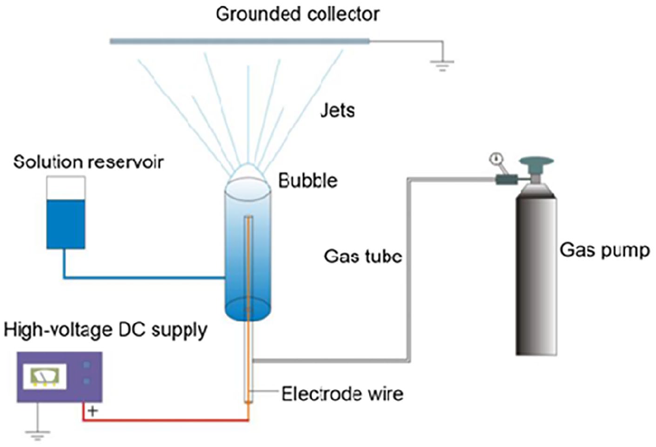
A schematic setup of bubble electrospinning. 90
Important factors in fiber formation are solution concentration, voltage, tip to collector distance (TCD), electric field strength, number of bubbles, and temperature.
Concentration of the polymer solution influences the morphology of the nanofibers. The development of beaded fibers can occur at lower concentrations (⩽14 wt %). In contrast, larger concentrations (⩾16 wt%) typically result in more homogeneous nanofibers. 91 The applied voltage has a significant impact on the nanofibers’ diameter. The average diameter of the nanofiber decreases when the applied voltage is increased. This is because greater voltages lead to narrower bubble jet which produces finer fibers. 92 It’s important to consider the TCD. Shorter TCD may lead to produce beads due to inadequate solvent evaporation and insufficient nanofiber stretching. On the other hand, as TCD increases, the charged jet accelerate which decreases the diameter of the nanofibers and bead production. 93
An electric field causes charges to be induced on the bubble surface, which causes deformation and the creation of upward-directed jets. It’s important to control the electric field strength carefully because if it’s too high, the bubble may burst, leading to poor-quality nanofibers. 94 The quantity of bubbles has a direct impact on the nanofiber throughput. The possibility of creating nanofibers rises with the number of bubbles since more bubbles can produce more daughter bubbles. A major determinant of the number of daughter bubbles that can be produced from a single giant bubble is the conservation of surface area during bubble interactions. 95 The bubble’s surface tension is greatly influenced by both the internal and external temperatures. A “zero-tension” state, which is favorable for the electrospinning procedure and properties of produced nanofiber, can be attained by regulating these temperatures. 96
Properties and morphology of electrospun nanofibers
Effect of properties on nanofibers morphology
Table 2 lists out the nanofiber’s parameter and its effect on fiber morphology.
Fiber parameters and their effects on fiber morphology.

Polymer concentration
The SEM pictures of three distinct PLA solutions in PLA-g-poly (DMAEMA) are displayed in Figure 13. In contrast to Figure 13(c), where the diameter is the biggest but irregularity is at its pinnacle, Figure 13(b) seems to have a uniform diameter and extremely regular forms, while Figure 13(a) shows uneven diameters with few thick and few considerably thinner fibers. The fiber thickness in these figures may be explained by the fact that the fiber diameter reduces as the PLA content in the solution does, and vice versa. However, as we raise the proportion to 15%, the fiber diameters become more irregular and less consistent. 114
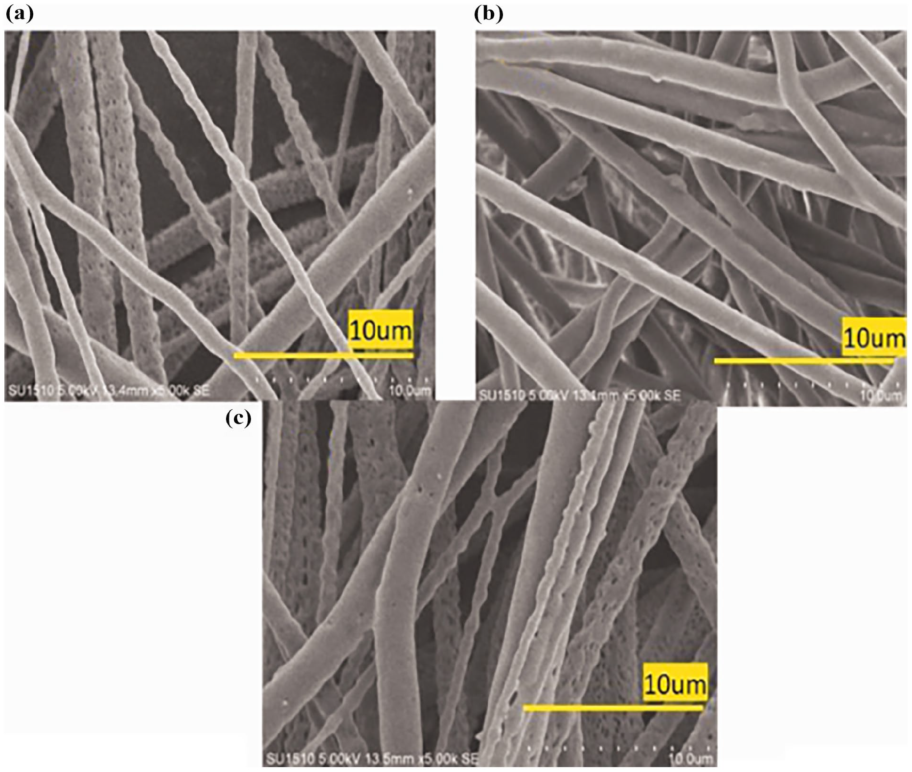
Effect of polymer concentration on nanofiber morphology—scanning electron micrographs with 10% PLA (a), 12% PLA (b), and 15% PLA (c). 114
Solvent volatility
The morphology of the polycaprolactone nanofibers with chloroform as a solvent was homogenous and granule-free, as seen in the SEM pictures (Figure 14). By electrospinning a PCL solution with a chloroform solvent, bigger diameter fibers were produced. Additionally, the widths of these fibers varied widely in value. Additionally, this nanofiber’s morphology sets it apart from others: Chloroform’s decreased viscosity causes the filaments to form in ordered layers and have a regular shape. In contrast, randomly formed fiber strands containing PCL polymer clusters are seen in PCL nanofibers subjected to acetic acid. 115

Comparison of the elastic modulus of electrospun polycaprolactone nanofibrous scaffolds: (a) PCL and acetone; (b) PCL and acetic acid; (c) PCL and chloroform. 115
Surface tension
When there is a large concentration of free solvent molecules, surface tension causes the molecules to coalesce and take on a spherical shape. The solution elongates under the electrical field due to the intense interaction between the solvent molecules and the polymer at high viscosity. The solvent molecules will disperse from the polymer molecules due to the electrical field, which also lessens the solvent molecules’ tendency to aggregate under the influence of surface tension. Figure 15 shows the effect of surface tension on the surface morphology of nanofibers. 116

Effect of surface tension on the surface morphology of nanofibers. 116
Solution viscosity
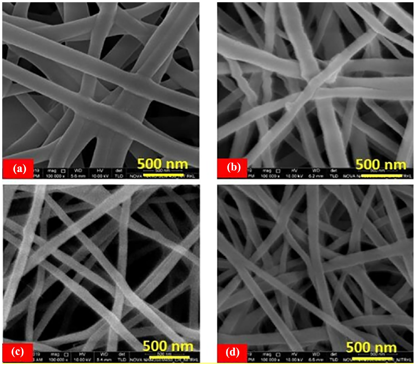
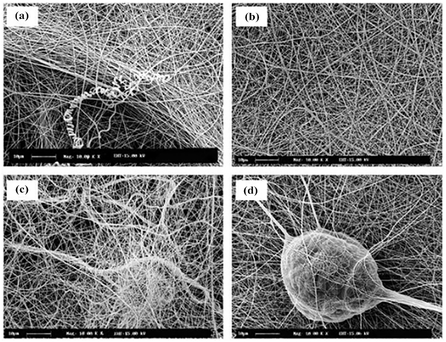
Figure 16 illustrates the effect of solution viscosity on fiber morphology under various conditions.

(a) Low viscosity sol–gel (0.119 Pa s) without voltage compensation forms droplets that reduce quality (b). High viscosity (0.194 Pa s) of the sol–gel forms very poor quality and non-uniform fibers (c). Sol–gel with ideal viscosity (0.141 Pa s) makes ultra-fine uniform nanofibers with a size of around 500 nm (d). The morphology of nanofibers as a factor of viscosity.101,102
Applied voltage and collector distance
SEM pictures and statistical analysis are used in this work to determine the link between voltage and fiber morphology. When the voltage rises, branch-shaped fibers and high pore sizes are seen in Figure 17. The following explanation applies to this: High voltages cause many electrospinning jets, which stretch the fibers and lower electrostatic forces, resulting in shortened fibers. Furthermore, branching constructions may affect the mechanical results, and higher voltages (20 and 25 kV) provide sites of contact between fibers (see closed sections in Figure 17(c) and (d)). When the voltage rises from 15 to 20 kV, an increase in the fiber diameter is typically seen (Figure 18). Higher voltages accelerate the jet in the direction of the collector, which shortens the flight time needed to stretch the jet before deposition and enables the production of fibers with a greater diameter. 117 Additionally, Figure 18 shows nanofiber’s morphology effect by collector distance, and Figure 19 depicts the graph of increases of fiber diameter with applied voltage.

Micrographs (left-side) and fitted normal distribution curve (right-side) of the PCL fiber diameters obtained at applied voltages: (a) 10 kV, (b) 15 kV, (c) 20 kV, and (d) 25 kV.FiF. 117
Effect of the needle tip to rotor collector distance on electrospun nanofiber morphology from a 5 wt% total polymer solution of chitosan/PEO (flow rate = 0.4 mL/h, applied voltage = 20 kV). Needle tip to rotor collector distance is (a) 10 cm, (b) 12.5 cm, (c) 15 cm, (d) 17.5 cm 118 (License Number 6037100634553).

Average fiber diameter of scaffolds as a function of the applied voltage. The standard deviation is included. *Statistical changes were obtained by comparing the lowest values with 15, 20, and 25 kV. 117
Flow rate
The beginning droplet’s form and part of the fiber morphology were found to be dramatically changed by the applied flow rate modification. The SEM picture in Figure 20(b) showed that by selecting the right flow rate, more uniform fibers were created and fewer defects including lumps, splitting, and branching fibers were formed. 106
The SEM images of the electrospun nanofibers at various flow rates: (a) 0.1 mL/h, (b) 0.5 mL/h, (c) 1 mL/h, and (d) 1.5 mL/h. 106
Relative humidity and temperature
In order to determine the ideal ambient conditions with the fewest experiments, Figure 21 displays an array of nine combinations of controlled parameters for three controlled temperatures (17.5°C, 25.0°C, and 32.5°C) and three controlled humidities (20%, 50%, and 70% RH). 119 Moreover, Figure 22 shows the SEM images of electrospun PLAL prepared from 20% w/v concentration at low relative humidity (a-b) and high relative humidity.

Scanning electron microscopy images (10,000×) of nanofibers produced under different controlled environment conditions. The white scale bar indicates 1 μm. 119

SEM images of electrospun PLAL prepared from 20% w/v concentration at low relative humidity (a-b) and high relative humidity(c-d). 109
Molecular weight
Figure 23 showed the impact of PLA’s molecular weight on the mechanical characteristics of electrospun PLA nanofiber sheets. Because of increased chain entanglement, PLA with a higher molecular weight showed a greater percentage of elongation at break in both the flow and crossflow directions. Young’s modulus decreased when PLA’s MW increased. There was no discernible improvement in tensile strength. 109

Tensile strength (a), % Elongation at break (b) and Young’s modulus (c) of electrospun PLA nanofiber at different molecular weight, concentration and relative humidity. 109
Physiochemical properties, nanofibers names and polymer solution used
Table 3 distinguished among the processes and their effect on physiochemical properties with application areas and fiber length.
Various electrospinning processes and their effect on physiochemical properties with application areas and fiber length.
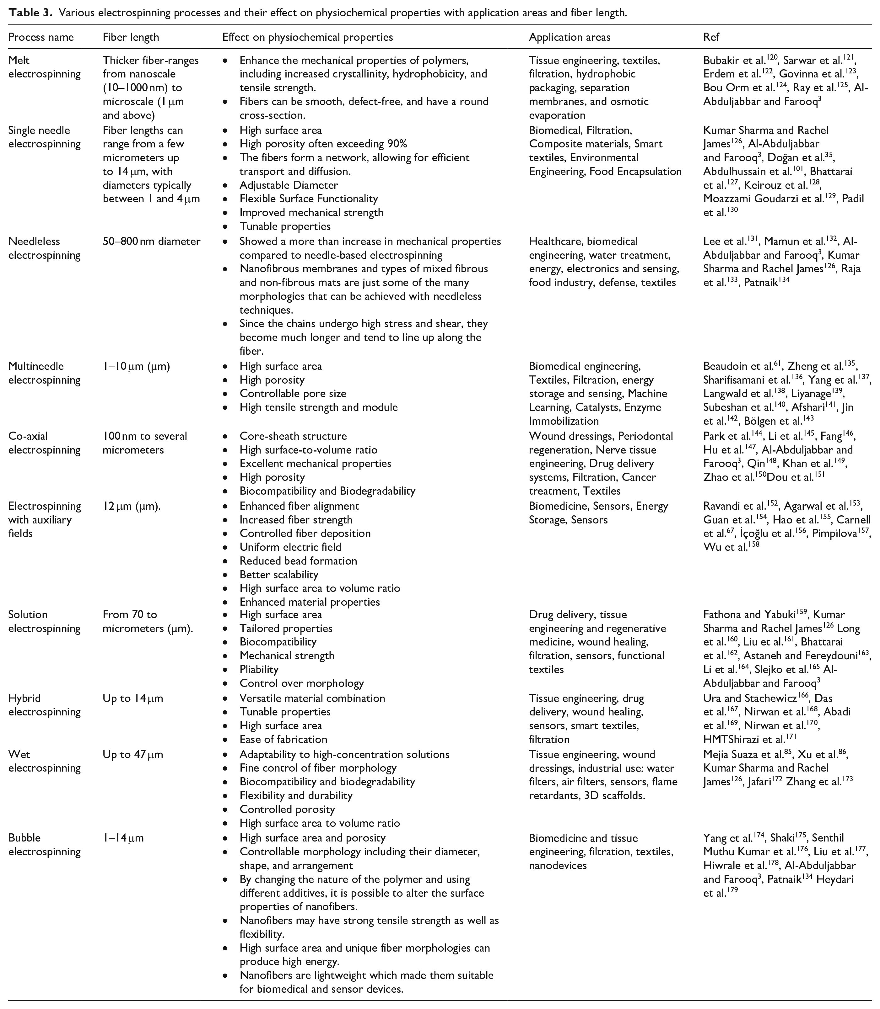
Table 4 listed the nanofibers produced by different electrospinning methods and their properties.
Nanofibers produced by different electrospinning methods and their properties.

Electrospinning can morph a wide range of polymers to nanofibers for a number of applications demonstrated in Table 5 given below.
Electro spinnable polymers to produce nanofibers.

Limitations of electrospinning
Stochastic fiber deposition: The erratic and stochastic fiber deposition is one of the primary drawbacks of electrospinning. Uniform fiber placement is challenging because of this randomness, which results from the polymer stream’s chaotic motion as it gets closer to the collection surface. High voltages are usually needed for electrospinning to generate the required electrostatic fields which limit the process’s scalability for industrial applications and poses safety hazards. 226 However, Robinson et al. found that the use of auxiliary electrodes helps stabilize the electric field, diminish erratic jet movement, and enhance fiber alignment. 227
Expandability: Another primary drawback is expandability. It works well in laboratories, but because of its low production rates, it is difficult to use in large-scale manufacturing. 228 Despite its versatility, electrospinning’s existing methods to produce electrospun scaffolds lack consistency and scalability especially in case of clinical needs since the scaffolds lack the mechanical strength required for load-bearing applications. 229 Moreover, the limited flow rate of single-needle electrospinning limits its industrial scalability. 33 Compared to conventional techniques, needleless electrospinning offers expandability, greater scalability and throughput. 230 By using more than one spinneret, throughput may be greatly increased and more nanofibers can be produced. 231
Small pore size: Cell migration and nutrient flow may be restricted by the relatively small pore size found in electrospun scaffolds. It may become difficult to support the growth of larger tissue constructs as a result of insufficient cellular connections and tissue integration. The intrinsic structural properties of electrospun scaffolds frequently limit their capacity to regenerate thick and complicated tissues. 232 3D scaffolds with larger pore sizes may be produced by using wet electrospinning or layer-by-layer assembly techniques. This improves cell infiltration and makes it possible to generate scaffolds with pore sizes appropriate for tissue regeneration. 233
Complexity: Voltage, the distance between the spinneret and collector, and solution characteristics are only a few of the variables that must be precisely controlled during the complex electrospinning process. Due to this intricacy, producing membranes consistently may prove difficult. There is a limited range of polymer types that can be utilized in electrospinning. In membrane distillation applications, the polymers need to be hydrophobic and insoluble. This limitation may prevent a wider variety of materials that could provide superior performance from being explored. Materials like fluorinated solvents that are used to modify electrospun membranes to improve their characteristics can be costly and even hazardous. 234
Irreproducibility: Electrospinning’s inability to reliably produce the same output is one of its major disadvantages. The diameter and shape of the fibers can be impacted by changes in temperature and humidity, which might result in inconsistent final products. The inability to automate the electrospinning process may make it difficult to use in industrial settings. 235 Parallel processing made possible by the use of numerous spinnerets can boost throughput and possibly enhance repeatability. 236
Issue in producing inorganic nanofibers: Another major obstacle to electrospinning is the difficulty of creating inorganic nanofibers. Because inorganic materials frequently possess many of the required features of nanofibers, this constraint limits the spectrum of materials that can be used in different applications. Obtaining a homogeneous polymer solution is essential to create consistent nanofibers. 237 Highly aligned or orientated inorganic nanofibers, which are preferred for particular applications, might be difficult to produce via electrospinning. 238 The variety of materials that can be electrospun can be increased by research into methods like melt electrospinning and liquid-assisted electrospinning. 239 Stable fiber creation may be achieved by experimenting with greater voltage ranges and fine-tuning jet characteristics, particularly for materials that need higher charge. 101
Needle Clog: Conventional electrospinning techniques frequently include needles, which can clog with polymer solutions and cause delays in the fiber-making process. This problem has the potential to drastically lower the electrospinning setup’s output and efficiency. The consistency of the fiber mat may be jeopardized if the needle tip becomes clogged. 240 Researchers are investigating needleless electrospinning, which produces nanofibers without a needle, and optimizing solution parameters including solvent type, polymer concentration, and applied voltage in order to reduce needle clogging. 241
Uneven Taylor cone: A key component of fiber synthesis, the Taylor cone, can form unevenly and uncontrollably in conventional electrospinning. This may result in differences in fiber quality and diameter, which makes it challenging to get reliable findings. 241 Stable fiber creation may be ensured by preventing water condensation in the Taylor cone by environmental optimization, such as maintaining proper humidity levels. 242
Toxicity from solvents: Hazards of toxicity may arise from the solvents used in the electrospinning procedure. The final product may contain residual solvents, which could have negative consequences if applied in biomedical settings. The quality and consistency of the nanofibers may be challenging to maintain when production moves from small to large scale. 243
Lacking adhesion: The adhesion between the nanofiber mats and the substrate may not be enough when electrospinning onto stiff substrates, such as those composed of poly lactic acid (PLA). This lack of adherence may cause the nanofibers to separate from the substrate, which would restrict the composites’ usefulness. 244 Adhesion can be increased by applying chemicals or plasma to the substrate or electrospun nanofibers to increase their surface energy and wettability. 245 Polymers’ mechanical strength and adherence to other materials can both be enhanced by crosslinking. 246
Uneven and imprecise deposition: The electrospinning process may be impacted by the 3D printed objects’ surface. The performance of the final composite may be harmed by uneven nanofiber deposition caused by an uneven or poorly defined surface. 247 The inability to regulate the location of fiber deposition is also another issues with electrospinning. Because of this unpredictability, electrospun devices may behave differently, making it challenging to produce reliable outcomes in large quantities. The deposited polymer fiber may move chaotically in an unstable area during the electrospinning process. This instability can impact the quality of the fibers generated and makes it more difficult to manage precisely for efficient fiber insertion. 248 One major difficulty in multi-needle electrospinning is the deviation of electric field distribution due to “Coulombic repulsion” of charged jets and needles. Poor fiber quality may result from this unevenness. Reductions to process uniformity improvement were obtained with introduction of parallel plate auxiliary electrodes, significantly improving the process. 52
Applications
Textiles
By precisely controlling the fiber’s diameter, shape, and composition, electrospinning makes it possible to customize characteristics like porosity, mechanical strength, and surface chemistry. 249 Numerous polymers, both natural and manmade, may be used to create electrospun fibers, opening up a variety of uses. 250 Although electrospinning is scalable for industrial manufacturing, it may also be carried out on a small scale. 126 Certain capabilities, including antibacterial activity, UV protection, or temperature control, can be improved by adding nanoparticles, dyes, or other useful additions to the electrospinning solution. 252 Hybrid materials with improved performance can be produced by combining electrospun fibers with other textile materials, such as conventional yarns or textiles. 251 Nanoscale smart materials and electrospinning may be coupled to produce fibers with minimum flaw that react to light, pH, temperature, and electric fields, among other environmental stimuli and find uses in wearable technology and other cutting-edge textile innovations. The number of electrospun nanofibers in a unit area of cross-section is dramatically increased improving flexibility and functionality. Moreover, two very crucial but contradictory properties of fibers which are high toughness and high strength were provided in the same fiber. This yarn was developed from poly (acrylonitrile-co-methyl acrylate) with a few poly (ethylene glycol) bisazide servicing as crosslinker, followed by annealing under tension.223,252,253 Conductive textiles may be created by electrospinning polymers, such polyurethane (PU), and coating them with conductive materials, like PEDOT: PSS. These materials are useful in wearable electronics because of their stretchability and dependable electrical properties under stress. 254 Sound absorption and filtration are two other areas where nanoscopic electrospun nonwoven textile material are being used. 255
Tissue engineering
Electrospinning can produce nanofibrous scaffolds that mimic the extracellular matrix (ECM) that is, they provide an environment that is conducive to tissue regeneration and cell proliferation. 256 Because of their high surface area to volume ratio and variable porosity, electrospun fibers are ideal for applications requiring high surface contacts, such as filtration, distribution of medications, and tissue engineering sector. 257 Electrospinning allows for the customization of mechanical and biological properties by using a range of materials, such as natural polymers, biodegradable polymers, and non-degradable polymers. 258 Having wide surface area and porosity, they can promote cell adhesion, proliferation, and differentiation—all necessary for effective tissue engineering. 239 Bioactive materials such as proteins, growth factors, and antibiotics may be added to electrospun scaffolds to promote tissue regeneration and allow for controlled medication release. 259 Linked fiber networks can enhance tissue development, nutrition delivery, and cell penetration within the scaffold. 260 Many tissue engineering domains, such as skin, nerve, cartilage, bone, and urologic tissues, have effectively used electrospinning. 261 Advancements in electrospinning methodologies in recent times have been directed toward refining scaffold construction, augmenting cellular infiltration, and directing cell activity to more accurately emulate tissue characteristics. 262 Techniques for encapsulation, chemical immobilization, and plasma treatment alter fiber surfaces to improve their performance. Chemical immobilization binds bioactive molecules for cell signaling and differentiation, plasma treatment enhances hydrophilicity and cell adhesion, and encapsulation techniques allow for targeted distribution and controlled drug release.263,264 However, limitations including scalability, solvent toxicity, and cell penetration must be resolved. 265 Figure 24 shows an illustration of nanofiber in tissue engineering. 232

A schematic of application of electrospinning in tissue engineering. 232
Drug delivery system
High surface-to-volume ratio electrospun nanofibers improve mass transfer and drug loading which is advantageous for drug delivery applications. 266 Reduced drug administration frequency, enhanced treatment effects, enable controlled and prolonged release, fast-dissolving drug delivery, combining several medications resulting reduced adverse effect and synergistic benefit, modifying fiber alignment and structural properties to control the drug release speed are the merits of using electrospun nanofiber. 267 This is especially helpful for intricate physiological processes including the avoidance of surgical adhesions and tissue regeneration.268,269 It is possible to change the fibers’ release characteristics, improve their biocompatibility, or permit targeted administration by altering their surface, for instance, by coating them with biocompatible polymers or nanoparticles. 270 Complex, three-dimensional drug delivery systems may be made by using electrospun nanofibers as a 3D printing medium. 271 Coaxial electrospinning can produce core-sheath nanofibers, which can control the early burst release of medications and provide a more continuous release profile.255,272 The technique may incorporate a broad spectrum of polymers and pharmaceuticals, including proteins, DNA, RNA, antibiotics, and anticancer medications. 273 Figure 25 depicts nanofibers for drug delivery. 180

Nanofibers for drug delivery. 269
Dressing wounds
Electrospun fibers, having high surface area to volume ratio and high porosity, are beneficial for wound healing (Figure 26). 274 Electrospun fibers can be made more biocompatible, cell-adhesive, or antimicrobial by adding certain chemicals or polymers to their surface. 275 Antibiotics, antimicrobial chemical such as silver nanoparticles and growth factors are examples of bioactive substances that may be added to electrospun wound dressings.276–278 This method makes it possible to create core-shell fibers, in which a protective barrier may be provided by the shell and a medicine can be put into the core. 279 Growth factors, cytokines, and other bioactive substances can be added to encourage tissue regeneration and cell proliferation. 280 It was observed that the antibacterial qualities of bacteria were improved by increasing the quantity of chitosan in the nanofiber composition. 281 The antibacterial qualities of nanofiber membranes are greatly increased by the addition of natural extracts like green coffee and antimicrobial drugs like Ciprofloxacin (CIP) . 282 Materials such as ZnO nanorods and Ag nanoparticles can be incorporated into electrospun nanofibers to provide antibacterial, antiviral, and self-cleaning capabilities. 283 Electrospinning is used to blend natural (hyaluronic acid, collagen, and chitosan) and manufactured (polyurethanes, polyesters) polymers to create effective wound dressings. Properties such mechanical strength and biodegradability, may be specifically engineered into these materials.284,285 Electrospinning equipment can directly deposit nanofibers into wound sites. 286 The nonadherent and superabsorbent properties of electrospun materials can assist control wound exudate and lessen discomfort during dressing changes. 287

Representation of the properties that electro spun membranes must display to be used as wound dressing. 288
Air & water purification
Electrospun nanofibers are ideal for air filtration applications due to their high specific surface areas, connected nanoscale pore structures, low pressure loss, and superior filtration efficiency. 289 The method of electrospinning makes it possible to produce nanofibers with a variety of topologies (like core-shell, Janus, and multilayered) and functions (like flame-retardant, antibacterial, and volatile gas adsorption), which improves their suitability for use in air filtration (Figure 27).290,291 The electrospinning technique works well for creating fibrous mats of nanofibers with a large surface area. This method is perfect for a variety of filtering applications because it enables the production of a thin mesh that can capture tiny particles. 292 Advancements including the employment of water soluble synthetic polymers based multistructured nanofibers (such nanoprotrusion, wrinkled, and porous) enhance the environmental friendliness and scalability. 293 The mechanical stability may be improved by combining 3D-printed polymers with electrospun nanofibers, reducing damage and increasing their longevity. 250 Electrospun nanofibers are used air filtration applications such as masks and filters for PM2.5, volatile organic pollutants, and bacteria, to address issues with indoor and outdoor air quality.294,295 Capacity to eliminate sub-micrometric and nanometric particles from water streams makes them promising for application in water filtration as well (Figure 28). 296 Limitations include need for increased mechanical stability and the use of hazardous solvents during the electrospinning process. 293
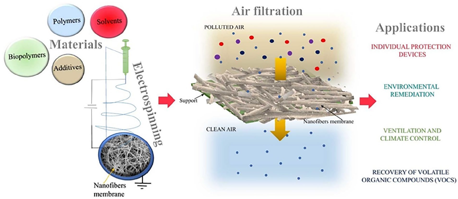
A schematic diagram of air filtration 297

A schematic diagram of water purification. 298
Protective clothing
When it comes to breathability and thermal comfort, electrospun fibers and membranes outperform traditional protective materials, which sometimes lack these qualities. Higher air permeability, vapor transfer, and thermal insulation qualities of electrospun polyurethane webs improve user comfort (Figure 29).299–301 Since electrospun membranes may be made to withstand fire, they are appropriate for use in protective equipment for firefighters . 302 In agricultural settings, electrospun polypropylene webs provide exceptional barrier performance against liquids with different surface tensions when utilized as protective clothing. 303 High filtration efficiency is demonstrated by electrospun membranes, which successfully capture airborne particles and create a thin, multipurpose barrier. 304 To enhance the functional features of electrospun textiles, such as gas purification and the removal of dangerous compounds, one type of material that may be added is metal-organic frameworks (MOFs). 305 With adjustable features including hydrostatic pressure resistance, high water vapor transfer, and ideal mechanical qualities, the technology facilitates the creation of novel materials. 20

A presentation of electro spun nanofibers based protective clothing. 306
Fuel cells
Electrospun catalyst layers greatly boost the power output of polymer electrolyte membrane fuel cells (PEMFCs) by increasing the surface area available for catalysis. Electrospun materials are used as direct electrodes or catalyst supports in PEMFCs to increase their durability and power output at low catalyst loadings, which is necessary for large-scale commercialization. 307
Gas diffusion electrodes (GDEs) and electrospun gas diffusion layers (GDLs) work together to improve oxygen movement and lessen mass transport constraints, increasing power density and eliminating the need for extra GDL sheets.308,309 Proton-conducting materials may be effectively accommodated by electrospun nanofibrous membranes with high porosity and surface area, improving both proton conductivity and mechanical qualities. 310 High-temperature PEMFCs can benefit from composite membranes that contain inorganic proton conductors, such as SiO2/heteropolyacid nanoparticles, as they improve heat stability and proton conductivity. 311 When combined with electrospun carbon nanofibers, zeolitic imidazolate frameworks (ZIF-67) improve the efficiency of the oxygen reduction process and the power density of microbial fuel cells. 312 Electrospun nanofibers are being researched for use in the fabrication of the cathodes and anodes in SOFCs operating at intermediate temperatures in an effort to increase efficiency and reduce costs (Figure 30). 313

Schematic presentation of (a) Preparation of an electrode from carbon fibers prepared through the electrospinning of polyacrylonitrile (PAN) nanofibers, their carbonization, decoration with in situ generated catalyst nanoparticles and deposition, after adding ionomer binder, onto a GDL or membrane. (b) Electrospinning of a catalyst/polymer ink into freestanding electrodes. 310
Sensors
Owing to their larger specific surface area, electrospun nanofibers are more sensitive and react more quickly than flat films and increases the sensitivity of optical sensors in detecting metal ions and other materials (Figure 31).314,315 Electrospun nanofibers may be employed in bio- and chemical sensors, gas sensors, and tactile sensors. 316 In strain and pressure sensors, conductive polymer nanofibers are very helpful because they provide increased sensitivity, robustness, and longevity. 317 The usage of piezoelectric polymers, such as PVDF and its copolymers in electrospun nanofibers, can lead to better performance of pressure sensors, beneficial to wearable electronics, and human activity monitoring. 318 Excellent mechanical durability, flexibility and thermal qualities are exhibited by electrospun fibers, which are essential for the dependability and functionality of sensors in a variety of environments.225,319

Potential applications of sensors and biosensors. 255
Future trend of electrospinning
The potential of conventional electrospinning techniques may be extended by employing tri-axial electrospinning, quad-fluid coaxial electrospinning, tri-fluid side-by-side electrospinning, and coaxial electrospinning with a side-by-side core to create complex multi-compartment nanostructures.320,321 For instances, core-shell nanofibers can be produced using coaxial electrospinning. 322 The technique of microencapsulation, which allows for the encapsulation of different substances, such as medications and biological materials, within fibers, has also been enhanced by co-axial electrospinning. 323 The method makes it possible to build porous and hollow structures. Its adaptability in the medical arena is being demonstrated by its current exploration for use in cardiac patches, nerve grafts, bone grafts, and skin grafts. 148 Also using a tri-fluid side-by-side electrospinning technique, tri-layer Janus fibers—two spinnable solutions and one unspinnable solution—can be produced. By lowering the restrictions on the kinds of materials that can be utilized, this development expands the range of medications that can be incorporated into the fibers. 324 Developments in tri-fluid side-by-side electrospinning provide new opportunities for the production of materials with multiple uses. 325 The development of a tri-channel spinneret is a major breakthrough in triaxial electrospinning. Integrated Janus nanofibers with two separate compartments can be created using the triaxial electrospinning method. 326 The interdisciplinary character of this technology is demonstrated by the creation of tri-layer and core-sheath Janus designs by using triaxial electrospinning. It opens the door for creative solutions in medication delivery and other fields by fusing concepts from pharmacology, materials science, and nanotechnology. 327 Production of core-sheath and tri-layer Janus architectures is made possible by developments in hybrid configurations. These structures may display special qualities like improved mechanical strength and selective permeability. Large-scale production can be facilitated by modernizing electrospinning using methods like LAUHS-ES, which boost throughput, guarantee quality, and stabilize the production process. 242 The 0.01–1 g/h yield from conventional electrospinning techniques is insufficient for industrial requirements. This pace has been further increased by modern technology; some have even reached 450 g/h. Additional energy sources, including electric fields or ultrasonic waves, can be combined with electrospinning to increase output capacity. 328
Conclusion
Electrospinning is a creative, adaptable and the most popular method for producing nanofibers with a wide range of applications in industries, environment, electronics, and medicine. This method produces nanofibers with general to customized characteristics such as a high surface area-to-volume ratio, adjustable porosity, and a variety of morphologies by utilizing high-voltage electrostatic forces. Several electrospinning technologies, such as melt, coaxial, single-needle, multi-needle, needleless, solution, wet, bubble and hybrid approaches have usefulness in areas such as sensors, filtration, wound healing, lightweight composites, protective gear, medication delivery, and tissue engineering. Their uses are further enhanced by adding functional elements and customizing fiber characteristics. Factors that affect the morphology of polymer concentration, solvent volatility, solution viscosity and surface tension, electric field strength, flow rate, collector type, tip to collector distance, ambient temperature and humidity, polymer molecular weight, spinneret/ nozzle diameter, and applied voltage. Scalability, preciseness, intricacy, toxicity, and reproducibility have been major issues. Furthermore, sustainable solutions are expected due to the high cost of materials and the environmental effect of solvents. Though some of the issues are getting resolved; still there is room for further research. The ongoing interest and future research concerning electrospinnable nanofibers include mitigating the obstacles of the processes and parameters, producing complex multi-compartment nanostructures, improving the quality of microencapsulation, delving the potential of using otherwise restricted materials, fusing concepts from pharmacology, materials science, and nanotechnology to produce new method of medication delivery and developing biomaterials, improving hybrid methods and combining auxiliary field electrospinning are being highly researched and developed.
Footnotes
Author Contributions
Conceptualization, R.I. and K.S.I.; resources, N.C., K.S.I., R.I., P.M., A.D., A.R.S.; data curation, N.C., R.I., K.S.I.; Writing—Review and Editing, N.C., K.S.I., R.I., P.M., A.D., A.R.S., N.S.; S.M.F.I.; visualization, N.C.; supervision, K.S.I.; project administration N.C.
Declaration of Conflicting Interests
The author(s) declared no potential conflicts of interest with respect to the research, authorship, and/or publication of this article.
Funding
The author(s) received no financial support for the research, authorship, and/or publication of this article.
Data Availability Statement
Data are contained within the article and proper citation. The figure we used has obtained permission.