
Abstract
Piezoelectric materials have garnered significant interest owing to width range of applications in sensing and energy harvesting by converting environmental mechanical energy to electricity. Improving the performance of piezoelectric nanogenerators (PENGs) is an important challenge to develop these devices. Herein, a novel method was used to enhance the piezoelectricity of the PENGs based on PVDF NFs (polyvinylidene fluoride nanofibers) and BaTiO3 NPs (barium titanate nanoparticles) by simultaneously electrospinning of PVDF NFs and electrospraying of BaTiO3 NPs. Two set of nanogenerator devices were prepared which differ in piezoelectric layer arrangements and volume fraction of piezopolymer and piezoceramic parts. Results showed that, in case of simultaneously electrospinning and electrospraying (E/E), a significant increase in piezoelectric phase content and voltage output has been observed in comparison with the layer by layer arrangement. The improved piezoelctric performace may result from better dipole alignment facilitated by a more intense electric field during the simultaneously E/E process, along with heightened interactions between the two materials arising from enhanced contact in a multilayer configuration. Moreover, the optimum volume ratio of piezopolymer to piezoceramic to obtain the maximum output was 1.5 to 0.5. Therefore, simultaneously E/E effectively enhance the piezoelectric performance without having the common challenges in the electrospinning process of nanocomposites, as well as decreasing the total preparation time and simplifies the processing steps. Having such features, leads to hold great appeal of these nanogenerators for diverse applications.

Highlights
In this study, different Layering and volume fraction of PVDF nanofibers and BaTiO3 nanoparticles were synthesized by simultaneously electrospinning and electrosparying method and their piezoelectric activity, was evaluated. The findings indicate that at layering the sample with a simultaneously electrospinning and electrosparying method had best output voltage; furthermore, the optimum volume ratio of PVDF/BaTiO3 had been calculated.
Introduction
The increasing demand for energy, the limited availability of fossil resources, and environmental challenges have led to the development of environmentally friendly technologies for harvesting and storing energy from the surrounding environment. 1 Piezoelectric nanogenerators (PENGs), owing to their ability to convert mechanical energy into electrical energy, have gained significant attention in recent years.2,3 Due to these unique properties, the piezoelectric materials have a wide range of applications in sensors,4,5 actuators 6 and generators.7,8 These materials can be divided into four categories include artificial and natural piezocrystals 9 (quartz crystal, 10 Tourmaline, 11 …), piezoceramics 12 (barium titanate, 13 Lead zirconate titanate 14 ), piezoelectric semiconductors 15 (Beryllium oxide, 16 cadmium selenide 17 ) and piezopolymers (PVDF). 18 Polymer-based PENGs inherently exhibit lower piezoelectricity compared to piezoelectric ceramics. However, recent advancements have led to the development of nanocomposites made from piezoelectric ceramic nanoparticles and polymers, aimed at enhancing the piezoelectric performance of PENGs.
PVDF is a widely used piezoelectric polymer, known for its excellent mechanical strength, chemical stability, and strong piezoelectric properties.19,20 It can be crystalize in five different crystal phases of α, β, γ, δ, and ε. 21 Among them the polar β and γ phases are responsible for piezoelectric properties which can be obtained by mechanical stretching, electric poling under high electric field and the nanofiller adding. 22 Another new method to achieve a high β phase fraction, is electrospinning. 23 Electrospinning is a versatile fabrication technique to produces ultrafine fibers from polymer solutions or melts by applying a high-voltage electric field. The produced nanofibers possess exceptional properties include high aspect ratios and large surface areas, owing to their nanoscale dimension. 24 The electrospun PVDF-based devices with enhanced mechanical and electrical properties along with superior flexibility, are well-suited for energy harvesting applications, particularly those that capture energy from human body movements, such as walking and other activities. 25 The β phase content of electrospun nanofiber can be further improved by several methods such as controlling the electrospinning parameters, regulating solvent systems and etc.26,27
Barium titanate is one of the most widely used piezoceramics, attracting significant attention for its high piezoelectric coefficient, lead-free composition, and cost-effectiveness. 28
Most of the researches, have used the solution casting method to prepare the PVDF/BaTiO3 nanocomposite.29–31 The incorporation of BaTiO3 filler into PVDF via this method results in an enhancement of the β phase, but the effect is limited. To achieve further enhancement, a post-poling treatment is required, which is a complicated process. In the last few years, some reports have addressed the electrospinning method to prepare PVDF-BaTiO3 composites.32,33 These developed PENGs showed an enhanced electroactive phase and piezoelectric output compared to previous method. But it was found that, agglomeration of the piezoceramic nanostructures greatly undermines the piezoelectric properties of the nanofibers, thereby restricting the output performance of PENGs. By considering this issue, Zhao et al 34 improved the interface between BaTiO3 and PVDF NFs by grafting a polymer onto the surface of BaTiO3 NWs, to avoid agglomeration, leading to high β-phase content in electrospun nanocomposite films. This method has also disadvantages owing to complication and limiting the utilization of these PENGs in practical applications. To address this issues, in our recent published work, 35 we proposed a new method by electrospraying of BaTiO3 NPs b PVDF NFs to prepare a sandwich structured nanocomposite with improved piezoelectric properties and without any challenges in the electrospinning process.
Building on this idea, we considered the possibility of achieving even higher performance by optimizing this design as a multilayer structure through simultaneously electrospinning and electrospraying (E/E) of PVDF NFs and BaTiO3 NPs. This design enables the creation of a multi-layered structure, where thousands of layers of these two materials are stacked on top of each other in a single structure. It is worth mention that, to our best knowledge, there has no report on the simultaneously electrospinning and electrospraying of PVDF with nanofillers.
Therefore, in the present work, we proposed a new PENG based on multilayer PVDF and BaTiO3 nanocomposite by simultaneously E/E which locates BaTiO3 NPs nanoparticles on the surface and intercepts trapped them into PVDF NFs. The piezoelectric output of prepared PENGs by this novel method were measured which showed a significant improvement rather than those prepared by layered design. Moreover, the different nanogenerator with varying volume fraction ratio of PVDF to BaTiO3 were prepared by E/E method. The piezoelectric performance were evaluated and the nanogenerator with optimum content was identified. By reducing the overall preparation time and minimizing processing steps, this method effectively enhances the output performance. As a result, it paves the way for expanding the practical applications of this technology.
Materials and methods
Materials
All reagents consist of granules form of PVDF (C2H2F2)n (Mw = 1800 g/mol, Mn = 71, Sigma Aldrich, USA), anhydrous N,N′-Dimethylformamide (DMF) (CH3)2NCH) (99%, Merck, Germany.), BaTiO3 (99%, less than 100 nm, Sigma-Aldrich, USA) and Acetone (C6H6O) (99%, Merck, Germany).
Analysis and instruments
Morphological investigations were conducted using an AIS2300 C model field emission scanning electron microscope (FESEM) manufactured by Seron Technologies Inc., South Korea. X-ray powder diffraction (PXRD) measurements were performed using an X-ray diffractometer from INEL, equipped with monochromatized Cu-Kα radiation (λ = 1.54056 Å) and a step size of 0.01671 degrees. The X-ray source operated at a voltage of 40 kV and a current of 30 mA. A Bragg-Brentano configuration was used as the source-detector geometry, along with a scintillation detector. Additional attachments, such as an anti-scatter slit (1°), divergence slit (1°), monochromator, and Soller slit (0.04 rad), were also utilized in this diffractometer. The samples were characterized using a scanning electron microscope (Seron Technologies AIS2100) with a gold coating. For electrospinning, a Medifsion MS-2200 machine with a rotary collector (diameter of 8.47 cm) and a DAIWHA pump was employed in the Electrospinning and Nanofiber Laboratory of the Textile Faculty at Amirkabir University of Technology. An ultrasonic stirrer, made by Hielscher, Germany, operating at a frequency of 20 kHz and a power of 1500 W, was used for complete dispersion of the nanoparticles in the polymer. To measure the piezoelectric output of the nanogenerators, an experimental device have been designed, consisting of an electric motor, a shaft and a load cell. The rotational movement of the electric motor is converted into a reciprocating movement of a vertical shaft, applying the cyclic vertical forces on nanogenerator devices, as illustrated in our previous published work. 36 It is available at the Institute of Materials Engineering and Advanced Technologies within the Faculty of Textiles at Amirkabir University of Technology. Image J (2022 version), Origin (2019 version), and IBM SPSS Statistics (version 26) software were utilized to measure the diameter of fibers and nanoparticles, create diameter distribution diagrams, and perform statistical tests on the samples, respectively.
Preparation of PVDF solution
The electrospinning solution was prepared by dissolving PVDF in a solvent mixture of DMF and acetone at a concentration of 23% w/w, with a solvent ratio of 6:4. Initially, PVDF granules were added to DMF and stirred for 2 h in a water bath maintained at 60°C. Afterward, Acetone was added and stirring continued for an additional 30 min to achieve an uniform and homogeneous solution. To prevent solvent evaporation and leakage of solvent vapour, the container was sealed with parafilm tape.
Preparation of BaTiO3 dispersion
A BaTiO₃ dispersion with a 5% w/w concentration in DMF was prepared using an ultrasonic stirrer for 40 min to ensure uniform distribution of the nanoparticles. Figure 1 shows a schematic of the simultaneous E/E apparatus used in this study, which consists of a high-voltage power supply for both the electrospinning and electrospraying feeders, two syringe pumps, two syringes (1 mL volume), two syringe needles (G22), and a rotational collector (an aluminum foil-wrapped cylindrical drum). The electrospinning conditions were kept consistent across all samples, with a feed rate of 0.2 mL/h, an applied voltage of 15 kV, and a distance of 17.5 cm from the needle to the collector. The electrospraying setup similarly maintained a constant applied voltage of 15 kV, a distance of 15.7 cm from the needle to the collector, adjusting the feed rate based on the experimental design. Schematic of simultaneously electrospinning of PVDF NFs and electrosparying of BaTiO3 NPs.
Preparation of nanogenerators
Several PVDF/BaTiO₃ nanocomposites were prepared under varying experimental conditions, including variations in layering order and the volume ratio of piezopolymer to piezoceramic. In the first part, samples with differing layering priorities were prepared, as schematically illustrated in Figure 2(a). The first sample, a blank control named Al-PVDF, consisted of electrospun PVDF nanofibers on aluminum foil. The second sample, labeled Al-PVDF-BT, involved spinning a layer of PVDF nanofibers onto the aluminum electrode, followed by the electrospraying of a BaTiO₃ layer, using 1 mL of solution for each layer. For the third sample, Al-BT-PVDF, a layer of BaTiO₃ was sprayed onto the aluminum foil first, followed by spinning a layer of PVDF. The fourth sample, Al-(PVDF + BT), was prepared by simultaneously electrospinning PVDF nanofibers and electrospraying BaTiO₃ nanoparticles onto the aluminum foil, and was named Al-(PVDF + BT). The volume ratios of PVDF and BaTiO₃ were the same across all these samples. (a) Schematic of difference layering priority of PVDF and BaTiO3, (b) schematic of a prepared nanogenerator, (c) An image of flexible prepared nanogenerator.
In the second part, samples were prepared using the simultaneous E/E apparatus varying the piezopolymer/piezoceramic volume ratios. These samples were coded as: 1PVDF+1BT, 1PVDF+0.5BT, 1PVDF+1.5BT, 0.5PVDF+1.5BT, and 1.5PVDF+0.5BT. To complete the nanogenerators, an aluminum layer was added as a top electrode on the prepared layers, as schematically illustrated in Figure 2(b). The electrical output was measured between the top and bottom electrodes. An image of the final prepared nanogenerator is shown in Figure 2(c).
Results and discussion
SEM
The surface morphology of all samples was analyzed using SEM, as shown in Figure 3. The average fiber and particle size distributions are presented in Figure S1. Figure 3(a) displays the SEM image of the blank sample, revealing that the average diameter of the nanofibers is 174 ± 24 nm (Figure S1-a). The SEM image of the Al-PVDF-BT sample is shown in Figure 3(b), where it can be observed that the nanoparticles have aggregated in certain areas. The average diameter of these nanoparticles is approximately 211 ± 28 nm, while the average diameter of the nanofibers is 149 ± 21 nm (Figure S1-b). The SEM image on nanogenerator based on PVDF and BaTiO3. (a) Al-PVDF, (b) Al-PVDF-BT, (c) Al-BT-PVDF, (d) 1PVDF+1BT, (e) 1PVDF+0.5BT, (f) 1PVDF+1.5BT, (g) 0.5PVDF+1.5BT, (h) 1.5PVDF+0.5BT.
In Figure 3(c), the SEM image of the Al-BT-PVDF sample shows that the nanofibers have an average diameter of about 159 ± 18 nm (Figure S1-c) and are free of nanoparticles on their surfaces. The SEM images of the nanocomposites prepared by simultaneously electrospinning and electrospraying with different ratios of PVDF to BaTiO₃ (1:0.5, 1:1, 1:1.5, 0.5:1.5, and 1.5:0.5) are displayed in Figure 3(d)–3(h), respectively. Evidence shows that these samples exhibited less aggregation of nanoparticles compared to the Al-PVDF-BT sample. In the Al-PVDF-BT sample, the BT nanoparticles remain on the surface of the nanofibers and stack upon one another after electrospraying, leading to increased aggregation. In contrast, during simultaneous E/E, the nanofibers and nanoparticles are interspersed, resulting in less aggregation.
Additionally, the sample with a 1PVDF+0.5BT ratio has the largest average diameter at approximately 305 ± 21 nm, while the 1PVDF+1BT sample has a smaller diameter of about 141 ± 10 nm for the nanofibers and 164 ± 24 nm for the nanoparticles, making it the second smallest in diameter among the samples.
This observation may be attributed to the effective distribution of nanoparticles during the stirring process using the ultrasonic method in the 1PVDF+1BT sample. In contrast, the 1PVDF+1.5BT sample exhibits the highest accumulation of nanoparticles, which is reasonable given the larger volume of sprayed nanoparticles.
The nanofiber diameter of the 1PVDF+1.5BT sample was measured at 137 ± 14 nm, while the nanoparticles had an average diameter of 512 ± 49 nm. The 0.5PVDF+1.5BT sample ranks second in terms of fiber diameter, with fibers measuring 256 ± 24 nm, alongside nanoparticle accumulations measuring 170 ± 13 nm. This increase in diameter may be attributed to the imbalance between the two components of the composite, resulting from reducing the polymer content to the lowest volume (0.5) while increasing the nanoparticle volume to the highest level (1.5). Conversely, the 1.5PVDF+0.5BT sample exhibited the smallest fiber diameter among all samples, with an average diameter of 124 ± 12 nm for the fibers and 139 ± 19 nm for the nanoparticles. It can be concluded that the volume fraction of 1.5 for the polymer and 0.5 for the nanoparticles in the 1.5PVDF+0.5BT sample has facilitated entry into the optimal diameter range.
FT-IR spectroscopy
FTIR analysis was conducted on all prepared nanogenerators, as shown in Figure 4, to determine the crystal structure of the produced nanocomposites and to calculate the percentage of the beta phase. Figure 4(a) shows the FT-IR spectra of the nanogenerators with different layering order, while Figure 4(b) illustrate those for nanogenerators with different volume ratio of piezopolymer to piezoceramic. The FTIR spectrum of the neat PVDF nanofiber mats demonstrates vibration peak at 765 cm−1 associated to α phase, and the absorption bands at 840 and 1275 cm−1 characteristics of the β crystalline phase.
37
FT-IR spectra of the nanogenerators with (a) different layering order, (b) different volume ratio of piezopolymer to piezoceramic.
The percentage of the beta phase (f(β)), was calculated using equation below, where Aα and Aβ represent the absorptions at 765 and 840 cm⁻1, respectively.
37

The percentage of β phase of all prepared nanogenerators.

The enhanced the β-phase may arise from better alignment of the polymer chain dipoles which can be explained by two primary factors. First, during the simultaneous E/E process, PVDF experiences polarization under a stronger electric field. Second, there is an increased level of rearrangement resulting from the interactions between PVDF BT in a multilayer structure. This multilayer configuration, which comprises multiple layers of two materials, exhibits significantly higher levels of interaction compared to layer-by-layer setup, which typically includes only two layer of materials.
Furthermore, from Table 1 it was conducted that, among the PENGs constructed by simultaneously E/E, the one with 1.5 to 1 ratio of piezopolymer to piezoceramic, contain higher percent of piezoelectric β phase.
XRD
The XRD analysis was conducted to characterize the crystalline structure of the nanostructures. The XRD patterns of the samples with different layering order and different ration of materials are shown in Figure 5(a) and (b), respectively. Diffraction peaks at 17.6° and 18.5° are correspond crystal plane of the α phase, and the peaks at 20.1° and 22.2° are those for the β phase of PVDF, respectively.
36
The peaks of BaTiO₃ appear at 32.3° and 38°, corresponding to the (101) and (111) planes.
35
XRD pattern of the nanocomposites with (a) different layering order, (b) different volume ratio of piezopolymer to piezoceramic. The Crystallinity (%) of the nanocomposites with (c) different layering order, (d) different volume ratio of piezopolymer to piezoceramic.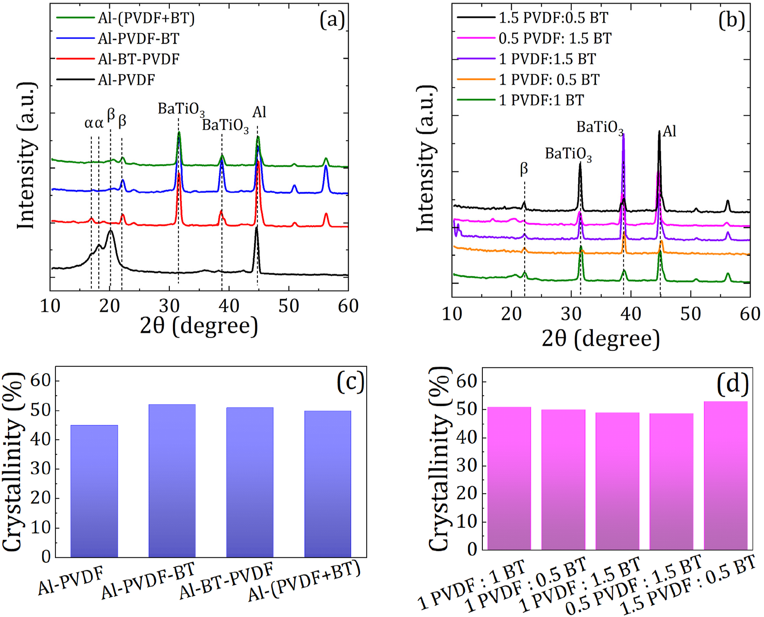
From Figure 5(a), it is observed that, the sample of Al-(PVDF + BaTiO3) are predominantly in β phase rather than the other samples which contains a combination of α and β phase. Therefore, the simultaneously E/E method, by creation of a multilayer structure, can obviously increase the value of piezoelectric phase which is caused by high interaction between the materials in such structures. This results are consistent with FTIR analysis. The difference of β phase content in the second group of samples (Figure 5(b)), cannot be recognized by using the XRD. For this samples, the FTIR and piezoelectric output results can clarify the difference.
Crystallinity percent of the samples were calculated by integrating the area under the crystalline peaks relative to the total area under the XRD spectrum, as illustrated in
Piezoelectric voltage output
The capability of the prepared piezoelectric nanogenerator to convert mechanical energy into electrical energy was investigated by applying vertical forces on the surface of the nanogenerators, by a mechanical device illustrated in Figure 6(a). In this device, the nanogenerators are secured between two plates subjected to periodic forces applied by the vertical shaft and their wires are directly connected to an oscilloscope, allowing for the measurement of the piezoelectric performance. The output voltage is calculated by measuring the peak to peak voltage of the each PENG. To ensure the repeatability of the results, three PENG samples were randomly prepared from each piezoelectric layer, and each PENG was tested four times and the mean value was taken as the representative response of the device. Therefore, each reported value for a piezoelectric layer represents the average of 12 tests. In this study, we utilized a 4N force with a frequency of 1 Hz for all tests.
Initially, the effect of layering priority on the final output of the nanogenerators was examined, as illustrated in Figure 6. Piezoelectric voltage output set up (a) and voltage output of the nanogenerators with different layering order.
The output voltage of the nanogenerators based on Al-PVDF, Al-PVDF-BT, Al-BT-PVDF, and Al-(PVDF + BT) were recorded as 2.09 V, 2.69 V, 2.03 V, and 3.77 V, respectively. Consequently, the Al-(PVDF + BT) sample exhibited the highest piezoelectric voltage output.
This improved piezoelectric performance may stem from the integration of electrospinning and electrospraying, where PVDF and BT are simultaneously subjected to two strong electric fields. This dual exposure facilitates a better alignment of their dipoles, ultimately improving their piezoelectric properties. Moreover, greater interactions between the two materials due to enhanced contact in a multilayer structure also play a significant role in optimizing their piezoelectric characteristics. These findings are consistent with the FTIR and XRD results. Notably, this method is time-consuming, which is a crucial consideration for practical applications.
Additionally, an analysis of variance (ANOVA) was conducted on the four samples to assess the differences in their means, as presented in Table S1. The results indicate that the piezoelectric voltage outputs of the nanogenerators with different layering orders show significant differences from one another, allowing us to conclude that the output values are comparable.
To explore the effect of the volume ratio of piezopolymer to piezoceramic on piezoelectric response, we compared the output voltage of nanogenerator devices with varying ratios of PVDF to BaTiO3, as shown in
Figure 7 The peak-to-peak voltage (Vpp) measurements for 1PVDF+1BT, 1PVDF+0.5BT, 1PVDF+1.5BT, 0.5PVDF+1.5BT, and 1.5PVDF+0.5BT were found to be 2.03 mV, 3.77 mV, 2.67 mV, 2.99 mV, and 4.85 mV, respectively. It is evident that the 1.5PVDF+0.5BT nanogenerator demonstrates the best performance among the samples tested. Piezoelectric voltage output of the nanogenerators with different volume ratio of piezopolymer to piezoceramic.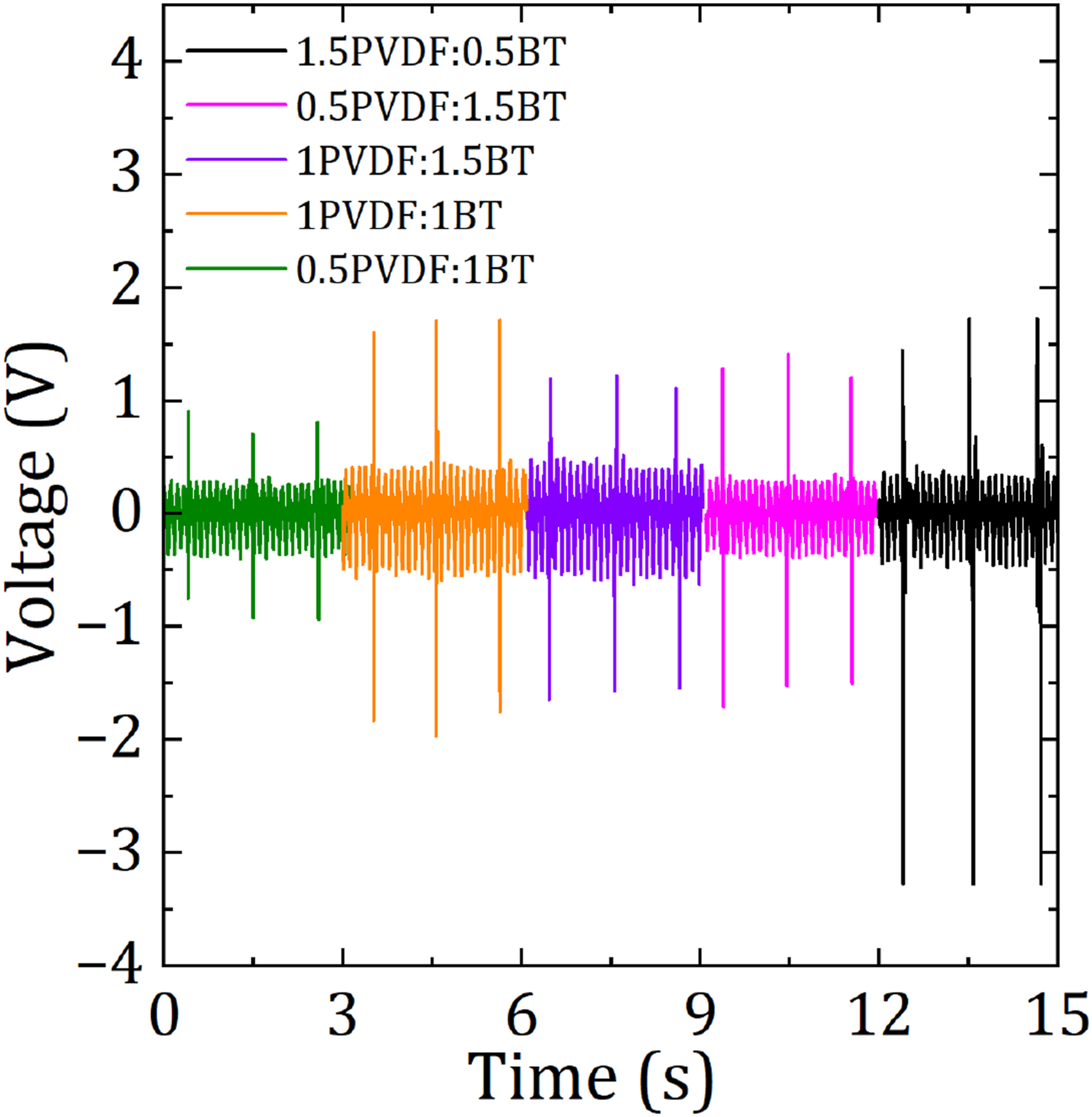
The results of the ANOVA analysis for these samples are presented in Table S2. As indicated, the output of samples with different volume ratios shows significant differences from one another, confirming that 1.5PVDF+0.5BT offers superior performance compared to the other configurations.
Conclusion
This present work, evaluate the piezoelectric performance of the PENGs based on PVDF and BaTio3 prepared by novel simultaneously electrospinning of PVDF NFs and electrospraying of BaTiO3 NP. This method provide a multilayered structure, where multiple layers of two materials are stacked, forming a single structure. The influence of layering order and component proportions on the structural and performance characteristics of the nanogenerator device have been examined. The PENG based on Al-(PVDF + BT), prepared by simultaneously E/E, showed higher β piezoelectric phase percentage and higher voltage output compared to Al-PVDF-BT and Al-BT-PVDF. The enhanced β phase may be attributed to improved dipole alignment due to a stronger electric field in the simultaneous E/E process, as well as increased interactions between the two materials resulting from greater contact in a multilayer structure.
Moreover, among the nanogenerators prepared by simultaneously E/E with varying ratio of PVDF to BaTiO3, the highest electrical output was obtained for 1.5PVDF:0.5BT. Overall, the simultaneous E/E method simplifies the preparation process and reduces time, while improving the piezoelectric performance, making it a promising approach for future research in this field.
Supplemental Material
Supplemental Material - A multilayer piezoelectric nanogenerator based on PVDF and BaTiO3 nanocomposite with enhanced performance induced by simultaneously electrospinning and electrospraying
Supplemental Material A multilayer piezoelectric nanogenerator based on PVDF and BaTiO3 nanocomposite with enhanced performance induced by simultaneously electrospinning and electrospraying by Maryam Tajik HesarAmiri, Pouya Khattami Kermanshahi, Roohollah Bagherzadeh, Maryam Yousefzadehc and Parisa Fakhri in Journal of Industrial Textiles.
Footnotes
Acknowledgments
The authors of this article are very grateful to all the people who helped them in this research in the electrospinning and nanofiber laboratory.
Declaration of conflicting interests
The author(s) declared no potential conflicts of interest with respect to the research, authorship, and/or publication of this article.
Funding
The author(s) declared the following potential conflicts of interest with respect to the research, authorship, and/or publication of this article: Iran National Science Foundation; 4020210; 4023636.
Supplemental Material
Supplemental material for this article is available online.
References
Supplementary Material
Please find the following supplemental material available below.
For Open Access articles published under a Creative Commons License, all supplemental material carries the same license as the article it is associated with.
For non-Open Access articles published, all supplemental material carries a non-exclusive license, and permission requests for re-use of supplemental material or any part of supplemental material shall be sent directly to the copyright owner as specified in the copyright notice associated with the article.