
Abstract
The needled/tufted interlocking fabric is a new fabric structure. At present, the mode II interlaminar shear behavior of needled/tufted interlocking composite has not been clarified. In this work, the needled/tufted interlocking fabrics and reinforced composites were fabricated, and the interlaminar shear behavior of mode II was studied experimentally and numerically, the mechanism of tufting effect on interlaminar shear properties of needled composites was revealed. The study found that the interlaminar shear properties of needled/tufted interlocking composites were greatly improved by tufted fiber bundles. The maximum failure load of the needled/tufted interlocking specimen increased 108.93%, and the interlaminar shear stress of the needled/tufted interlocking specimen improved by 89.39%. The interlaminar shear strength increased linearly with the increase of tufted fiber bundle implantation volume. The implantation pattern of tufted fibers had effected on interlaminar shear property. Under the same implantation volume, the thinner tufted fiber bundles and more implantation points were more beneficial to improve the interlaminar shear performance. The typical shear failure modes included matrix cracking, fibers pullout, and brittle fracture of tufted fiber bundles and needled fiber bundles. Moreover, a numerical simulation model of interlaminar shear behavior based on three cohesive zones (TCZMs) was proposed. The predicted displacement-load curves were highly in accord with the experiments. The error range was controlled within 1.08% - 3.76%. The simulation model could predict the mode II shear behavior of needled and tufted interlocking composites effectively, which was helpful to the early manufacturing process design of needled and tufted interlocking fabrics.
Keywords
Introduction
Needled composites have good interlaminar connection performance and are increasingly used in aerospace, new energy, rail transit and national defense.1–3 For different application scenarios, people proposed a variety of different needled fabric structures, mainly comprising of felt laminated needled fabric structures,4,5 which are mainly used as thermal insulation materials and commonly used in aircraft compartments; felt and woven cloth laminated needled fabrics.6–8 for brake disc material; moreover, felt and braiding cloth laminated needled fabrics.9–11 that are commonly adopted for thermal protection material, such as aircraft cabin and rocket engine nozzle.
Needled fabrics mentioned above all include a felt layer. Because the felt layer is airy, so the volume density of needled fabrics formed by using felt is small, and the interlaminar property is also weak, which cannot meet the mechanical performance requirement of hypersonic vehicle structural and functional integration components. Yao T et al.12–14 presented a new none-felt needled preform fabric, which enhanced the volume density of needled fabric, and greatly improved the in plane and interlaminar mechanical property, which was expected to satisfy the application requirements of hypersonic vehicle. Interlaminar interfacial performance. 15 is a key mechanical property of needled composites, and stitching 16 is an effective method for strengthening interlaminar performance. Xue L et al. 17 strengthen needled fabrics by use of “n” path stitching, carried out the preparation and characterization of needled/stitched coupled fabrics and their composites, and revealed the mechanism of compression damage evolution. Recently, Zheng H et al. 18 put forward of needled/tufted coupled fabric, and carried out research on the peeling property of needled/tufted composites. Needled/tufted coupled fabric is a new style fabric structure, and the influence of tufting on interlaminar shear mechanical behavior of needled composites has not been clarified, so this paper proposed to study the Mode II interlaminar shear behavior of needed/tufted interlocking composites.
In this work, needled/tufted interlocking fabric and its composites were designed and prepared, and the structure was characterized based on X-ray CT. Mode II interlaminar shear mechanical behavior of needled/tufted interlocking composite was explored, the influence of tufting on the interlaminar shear mechanical behavior of needled composite was studied, and the fracture failure mechanism of was revealed. In addition, based on the micro structure of the interlocking fabric, a numerical simulation model based on the three cohesive zones was established.
Materials and methods
Materials
Specifications of quartz materials.

Figure 1(a) presents the fabrication process of needled/tufted dual-scale interlocking preform, comprising of the needling and tufting processes. Firstly, the felt and base cloth were stacked and placed, and then the fabric was needled to the target thickness by a needling robot; furthermore, using a tufting machine, tufting was carried out according to the designed stitching spacing to achieve full thickness Z-direction fiber implantation of the needled preform. The needling robot.19,20 and tufting equipment.
18
for maunfactuing the needled/tufted preform were independently developed by Tiangong University, as shown in Figure 1(b) and 1(c). The type of needling needles was 15 × 18 × 36× 3 C333, and the stitching needle was DB × 1100/16. Fabrication process and machines of needled/tufted interlocking fabric. (a) Fabrication process; (b) needling robot; (c) tufting machine.
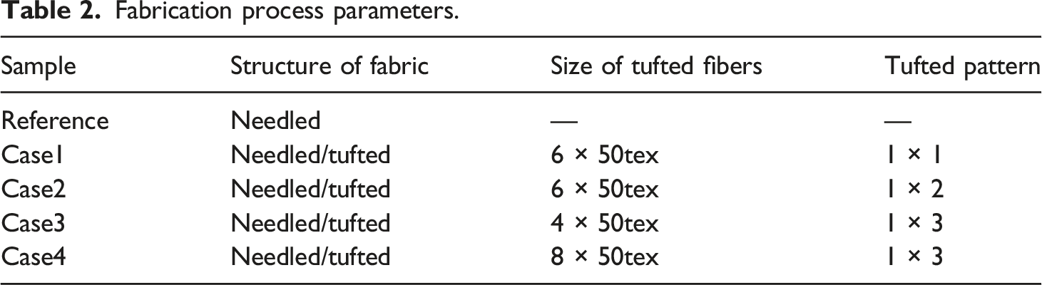
Fabrication process parameters.
Methods and technique
Micro-CT characterization
The mesostructures of needled/tufted interlocking fabrics were examined by Zeiss Xradia 510 versa X-ray machine. The source current and voltage were 100 μA and 100 kV respectively. Figure 2 shows the Micro-CT test process and results of the interlocking preform fabric. The size of test sample was 20 mm × 20 mm × 5 mm. The fabric structure 3D model was generated through the special image processing software-Dragonfly. Micro-CT test process and results of the needled/tufted fabric.
Mode II interlaminar shear experiment of needled/tufted interlocking composite
According to ASTM D 3846, mode II Interlaminar shear test samples were cut from 180 mm × 380 mm plate along the warp of base cloth by use of water jet cutting. The dimension of the test sample was 80 mm × 10 mm × 4 mm, as shown in Figure 3(a), the distance between the two incisions was 6.5 mm, and the width of the incisions was 1.5 mm. Figure 3(b) shows the double notch shear (DNS) test setup, the testing machine was AG-250KN universal testing machine of Shimadzu. The DNS adopted the stretching method. The loading rate was 1 mm/min, and there were 4 samples for each group. Mode II Interlaminar shear experiment. (a) Samples; (b) DNS test setup.
Results and discussions
Experiment
Structural characterization
As shown in Figure 2, from the X-Z section, the felt layer, base cloth layer, tufted fibers and needled fiber bundles were presented. The tufted fibers still remained twisted, this was because we had twisted the tufted yarn to reduce the probability of yarn breakage during the tufting process. Compared with the felt layer, the fiber bulk density of the base cloth and the tufted fibers was larger, which presented a brighter picture. The needled fiber bundles were T-shaped shape and realized the connection between adjacent layers, while the tufted fiber bundles effectively penetrated the full thickness of the preform. The X-Y section shows that the needled fibers and tufted fibers were roughly circular, and the diameters of tufted fibers were significantly larger than needled fibers, so tufting could significantly improve the interlaminar performance of composites. In addition, tufted fibers and needled fibers made the in-plane fibers of the base cloth bend obviously and the fibers were also damaged and broken by needles.
The diameter of tufted fibers and needled fiber bundles was quantified by Image Pro Plus software. The measured diameter is shown in Figure 4. The average diameter of the needled fiber bundles was only 0.237 mm, while the average diameter of tufted fibers (500tex) was 1.364 mm, and the measured diameters of needled fiber bundles and tufted fibers will be used as an important parameter input for the model Ⅱinterlaminar shear numerical model. The diameters of fiber bundles measured by Micro-CT. (a) Diameters of needled fibers; (b) diameters of tufted fibers of Case4.
Experimental result and analysis of mode II shear test
Figure 5 shows the typical displacement-load curve of the mode II shear test. It was found that the interlaminar shear property of needled/tufted interlocking composite was greatly improved compared with needled composite. The fracture failure load of needled/tufted interlocking specimen increased by 15.68% to 108.93%, and the interlaminar shear stress of needled/tufted interlocking specimen increased by 19.60% to 89.39%, as shown in Figure 6. Comparison of typical displacement - load curves of DNS test with different process parameters. (a) Case 1 and Ref.; (b) Case 2 and Ref.; (a) Case 3 and Ref.; (d) Case 4 and Ref. Comparison of the maximum failure load (a) and interlaminar shear stress (b) of DNS test.

From the displacement-load curve, it could be seen that the displacement load curve presented three stages, with the first and third stages showing a quasi linear growth trend, while the load plan remained unchanged in the second stage as displacement increased. This was because in the first stage, the resin matrix is mainly used for load-bearing, in the third stage, the resin and Z-direction fiber bundles were combined for load-bearing, and in the second stage, the resin matrix was transitioning to combined load-bearing. When the load increased to the maximum value, the sample broke, and then the DNS experimental value dropped precipitously, indicating that the tufted fibers, needled fibers in the thickness direction and matrix almost failed at the same time. Case 1, case 2 and case 4 showed that interlaminar shear strength increased linearly with the increase of tufted fiber bundle implantation volume, this indicated that the implanted tufted fibers carried more interlaminar shear stress. In addition, from the comparison of case 2 and case 3, it was found that the implantation pattern of tufted fiber bundles had effected on the interlaminar shear property. Under the same implantation volume, the thinner tufted fiber bundles and more implantation points were more beneficial to improve the interlaminar shear property. This was because the contact area between the fiber bundles and the matrix had increased, effectively improving the interlaminar shear resistance of the material.
Figure 7(a) shows the typical interlaminar shear failure modes of interlocking composite. The sample broke from the middle plane of the thickness direction, and the fracture was relatively flat, this fracture morphology also confirmed the cliff like decrease in load when reaching fracture failure in interlaminar shear experiments. Figure 7(b) and (c) are the SEM fracture morphology of needled fiber bundles and tufted fiber bundles respectively. It was found that the interlaminar shear fracture failure of needled/tufted coupled composites was due to matrix cracking, fiber bundles pullout and brittle fracture. Typical failure mode and SEM fracture morphology. (a) Typical failure mode; (b) needled fiber bundle fracture morphology; (c) tufted fiber bundle fracture morphology.
Numerical model and simulation
Cohesive zone model
Cohesive zone method (CZM).21,22 gives useful results for understanding interlaminar delamination of composites. In this method, the initiation and propagation of cracks are handled by cohesive elements according to traction separation law (TSL). 23 When the maximum traction force reaches, the damage begins, and when the critical fracture energy (GII of mode II) is reached, the crack propagates.
As shown in Figure 8, bilinear TSL is used to define cohesion laws. The relationship is defined by maximum traction force (TII), cohesive stiffness (KII), initial damage displacement (δinil), failure displacement (δfail) and critical fracture energy (GII). Mode II bi-linear traction separation law.
The method of developing a numerical model for predicting the mode II shear behavior of interlocking composites is shown in Figure 9. Three different cohesion laws are used to define mechanical behavior of matrix, tufted fiber bundle and needled fibers respectively. Diagram of numerical simulation scheme.
Based on Mode II shear tests of laminated composites, needled composites, and needled/tufted composites, cohesive parameters of matrix, needled fibers and tufted fibers were got respectively. First of all, the shear stresses of interlaminar matrix, needled fibers, and tufted fibers were caculated by Formula 1 and Formula 2 respectively. Equation (3) was used to define the cohesive stiffness KII of mode II, and GII was expressed by equation (4).
23


Numerical analysis was carried out on the Abaqus simulation calculation platform. Through double notch experimental research on needled/tufted interlocking composite, it was found that the fiber bundle failure mode mainly manifests as brittle fracture on the crack propagation plane. Therefore, this article uses an 8-node three-dimensional bonding element (COH3D8) to define the resin matrix, needled fiber bundles, and tufted fiber bundles in the crack propagation plane. In addition, 8-node linear hexahedral elements (C3D8R) were used to define double cantilevers, needled fiber bundles, and tufted fiber bundles outside the crack propagation plane. The specific details and mesh division of the three composite material finite element models are shown in Figure 10. Table 3 shows the cohesive parameters of mode II shear behavior. Finite element model and meshing. (a) Needled composite; (b) needled/tufted interlocking composite. Cohesive parameters of mode II interlaminar shear.

Finite element models of needled composite and needled/tufted interlocking composite
Figure 10 shows the finite element models and meshing of needled composite and needled/tufted interlocking composite. The semi-symmetric model of Abaqus software was adopted to improve computing efficiency. Fiber bundle diameter was a key numerical simulation parameter calculated by Micro-CT and Image Pro Plus. The average diameter of needled fibers was 0.207 mm, and the average diameter of tufted fiber bundle (400tex) was 1.364 mm. From this calculation, the diameters of 200tex and 300tex tufted fiber bundles were 0.682 mm and 1.023 mm respectively.
Mechanical property of material.

FEM results and discussions
Figure 11(a)–(e) is a comparison of load-displacement curves between test and finite element method. It was found that the predicted displacement-load results of the numerical simulation model were highly in accord with the experimental results, which indicated that the numerical calculation model of mode II interlaminar shear based on three cohesive zones constructed in this paper was feasible. Table 5 shows the comparison of the fracture failure load between experiment and simulation. It could be seen that the error range was controlled between 1.08% and 3.76%. Figure 11(f) is a strain nephogram of finite element simulation. With the increase of displacement, the strain gradually increases from the double notch position to the central area. According to the information of needing and tufting trajectory, the prediction model of interlaminar shear performance of mode II established in this paper could effectively evaluate interlaminar shear characteristics and contribute to the early process design of needled/tufted interlocking fabric. Comparison of load-displacement curve between experiment and FEM. (a) Ref.; (b) Case1; (c) Case2; (d) Case3; (e) Case4; (f) Strain nephogram of FEM simulation. Comparison of maximum failure load between simulations and experiments.

Conclusions
In this paper, needled/tufted interlocking fabrics and reinforced composites were fabricated, and interlaminar shear behavior of mode II was studied experimentally and numerically. The main conclusions were as follows: (1) Tufted fiber bundles significantly improved the interlaminar shear property of needled/tufted interlocking composite, and the maximum fracture failure load of specimens increased by 108.93%, the interlaminar shear stress improved 89.39%. The mode II shear strength increased linearly with the implantation volume increase of tufted fiber bundles. (2) The implantation pattern of tufted fibers had affected on the mode II shear performance. Under the same implantation volume, thinner tufted fiber bundles and more implantation points were more beneficial to improve the interlaminar shear performance. Typical failure modes of mode II shear included matrix cracking, fibers pullout, and brittle fracture of tufted fiber bundles and needled fiber bundles. (3) A numerical simulation model of double notch interlaminar shear based on the three cohesive zones was established. The predicted displacement-load results of the DNS numerical simulation model were highly in accord with the experimental results. The error range was controlled within 1.08% - 3.76%.The simulation prediction model will be helpful to the early manufacturing process design of needled and tufted interlocking fabrics. (4) Tufting is an efficient and low-cost reinforcement method. Needled/tufted interlocking fabrics and reinforeced composites are expected to be used in key core components such as radome, cabin and skin of ultra-long-range hypersonic aircraft.
Footnotes
Declaration of conflicting interests
The author declared no potential conflicts of interest with respect to the research, authorship, and/or publication of this article.
Funding
The author(s) disclosed receipt of the following financial support for the research, authorship, and/or publication of this article: This work was supported by the Science and Technology Foundation of National Defense Key Laboratory of Advanced Composite Materials (grant number 6142906210406), Scientific Research Project of Tianjin Education Commission (grant number 2018ZD13), the Tianjin Higher Education Innovation Team Project (grant number TD13-5043) and National Science and Technology Major Project (grant number 2017-VII-0011-0177), Natural Science Foundation of Tianjin (grant number 19JCYBJC18300).