
Abstract
Since the emergence of the first armoured vehicles on battlefields, armour shield was mainly centred on conventional metallic materials, widespread solutions nowadays. For a long time, weight reduction in armoured protection, which represents the largest part of the vehicle’s overall weight, has been the key parameter for vehicle manufacturers looking forward to optimizing fuel consumption, thus increasing the payload and offering increased manoeuvrability to vehicles. The solution generally developed is a combination between those metallic plates and materials lighter than the current steel armour. In this context, the hybridization of some well-known ballistic alloys with textile composite materials appears to be a high-potential solution for armour-plated protection. Indeed, used as a backing, textile composite materials present some worthwhile properties such as having a very low density compared with steel and good behaviour in terms of ballistic efficiency. The use of a textile composite backing allows a reduction in the thickness of the metal plate by a few millimetres, which has a huge impact on the total protection weight. The difficulty of this hybridization is, of course, to reduce the total mass of the protection solution as cautiously as possible while ensuring the safety of the vehicle. The textile composite backing is also efficient in containing the pieces of shrapnel, which might break loose from the metal plate during impact. However, observations from today’s military theatres of operation reveal that the spectrum of armoured vehicle threats has changed over the last decade with the development of new non-conventional threats commonly referred to as ‘improvised explosive devices’. Those devices generate high-velocity projectiles (accelerated up to a few hundred or thousand metres per second), which are able to perforate most existing armour plating. Thus, performances of today’s armoured solutions are required to be upgraded, in order to provide a better protection level. This improved protection level against new threats can be achieved by developing a composite backing more efficient to stop these projectiles. This study proposes to test and compare the behaviour and efficiency of three different textile composite backings used as up-armouring solutions. Two of those textile backings are innovative composite solutions developed in our textile laboratory, and the third one is a benchmark composite generally used as armouring protection. This study deals with the overall protection, and impact tests are performed on real armour configuration with the metal plate on the front face. Nevertheless, only the impact behaviour of textile composite backings has been investigated in this study. The parameters of the metal plate such as the nature of the alloy and its thickness were defined by our vehicles’ manufacturing partner and cannot therefore be communicated. They remain constant in the three configurations tested, allowing a clear comparison.
Keywords
Introduction
A wide range of composite products already exist as armouring solutions for vehicles generally made of uni-directional sheets or pre-impregnated plain weave fabrics.1–5 The most widespread yarns used for those specific impact applications are para-aramid (such as well-known brand names as Kevlar or Twaron) and high-modulus polyethylene (such as well-known brand names as Spectra or Dyneema). The resulting fabrics are assembled together with a matrix, like a phenol–PVB matrix often used for its fire resistance.
The nature of the composite used, its shape and its thickness depends on the part of the vehicle that the backing is designed to protect.
An important number of studies have been achieved in order to understand the impact behaviour of those composite materials as well as to improve those textile composite backings by optimizing the parameters of the fibrous reinforcement or the resin and its process [6].
The high velocity of projectiles generated by improvised explosive devices and their non-conventional impact law required armour protections to be up-graded in order to be able to resist such threats.
Few research results have been published on high-speed impact behaviour of composite solutions [7–11].
It is established in the literature that 3D warp interlock fabrics have different mechanical properties from 2D fabrics made of the same material, due to their specific bonding between layers [12–15]. Indeed, 3D warp interlock fabrics present a smaller damaged area and delamination and a better resistance to multi-hit impacts for a given impact.
The superior properties of the 3D fibre architectures in the case of an impact have been demonstrated in few publications [16,17]. Grogan et al. [17] in their experimental study tested ballistic impact vehicle armour panels with 2D and 3D-woven composite backings. It was shown that the best ballistic efficiency was reached by the 3D-woven backing, which tends to show a more controlled delamination but also less penetration.
Indeed, 3D-woven fabrics used as reinforcement in composite backing can be a more effective solution against impact than 2D-laminated composites as shown by Chen and Hodgkinson [18] and Baucom and Zikry [19], who performed comparative studies between the different reinforcements subjected to impact loading.
Taking into account the previous results of Lefebvre’s research works [20] done on the understanding of the mechanical behaviour of 3D warp interlock structures during high-velocity FSP impact (from 500 to 1000 m/s), different parameters as their geometrical structures, their density and the nature of yarns have revealed their main influence on the final behaviour of the material. Different geometrical structures of 3D warp interlock have also been compared using the same yarns and ends density, and it has been revealed that using equilibrated warp and weft densities leads to better impact protection. Additionally, the low rate of resin inside the 3D warp interlock structure tends to improve the deformability of the structure during the impact and reduces the matrix cracking. Only 3D warp interlock weaves have been produced instead of 3D orthogonal non-crimp as described in Bogdanovich and Mohamed [21] in order to involve the bonding warp yarns in the deformation behaviour of the structure during the impact.
Thus, in order to confirm the previous results with another impact velocity, different 3D warp interlock weaves will be studied in order to figure out which one is the most suited against high speed impact.
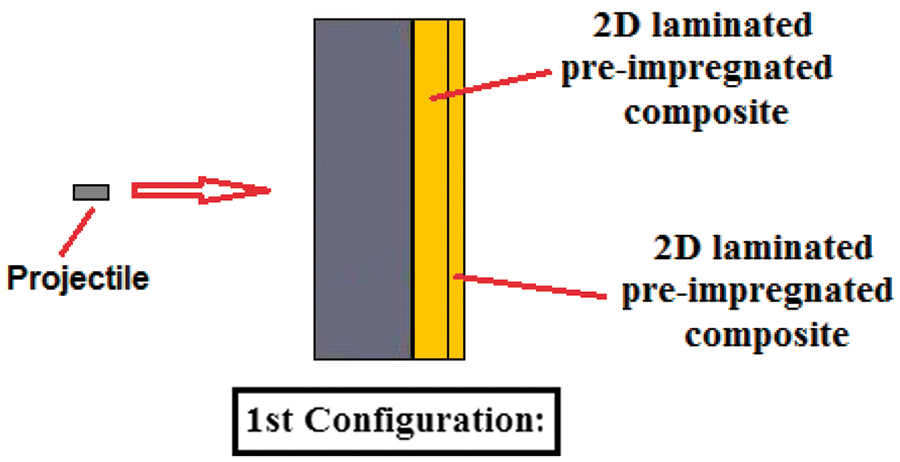
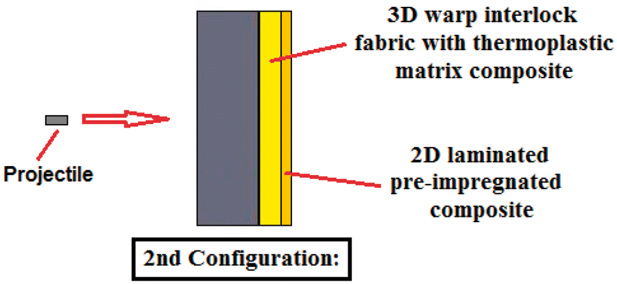
The three different textile backings tested in this study are a 2D-laminated composite (see Figure 1), a 3D warp interlock composite with a thermoplastic matrix and a 3D warp interlock composite with a thermosetting matrix (see Figure 2).
Cross-sectional view of an assembly of pre-impregnated 2D laminates. Cross-sectional view of one ply of 3D warp interlock fabric.

It was observed that all three textile backings feature quite different behaviours under impact.
Details of the three fibrous reinforcements
The 3D warp interlock structure chosen for this study features a bonding that is a mix of angle, orthogonal and layer-to-layer interlock. In this fabric, the layers are bonded 2 × 2, thanks to the progressive evolutions of three different columns of warp yarns (see Figures 2 and 3). The pattern on the upper and lower surface is a diagonal 4 × 3 pattern due to the fact that there are three different warp yarns evolutions.
Evolution of the warp yarns in the fabric structure.
The yarn implemented for this study is a para-aramid multi-filament, widely used in ballistic protection for its high tenacity and flame-resistant properties [22]. The size of the yarn chosen is 3360 dTex, which is the biggest yarn commercially available, commonly used in hard ballistic especially for vehicle applications.
Definitions of the four manufactured composites
2D-laminated composite
The first two composite plates are 2D-laminated, made of several pre-impregnated plies, widely used in heavy-duty ballistic protection.
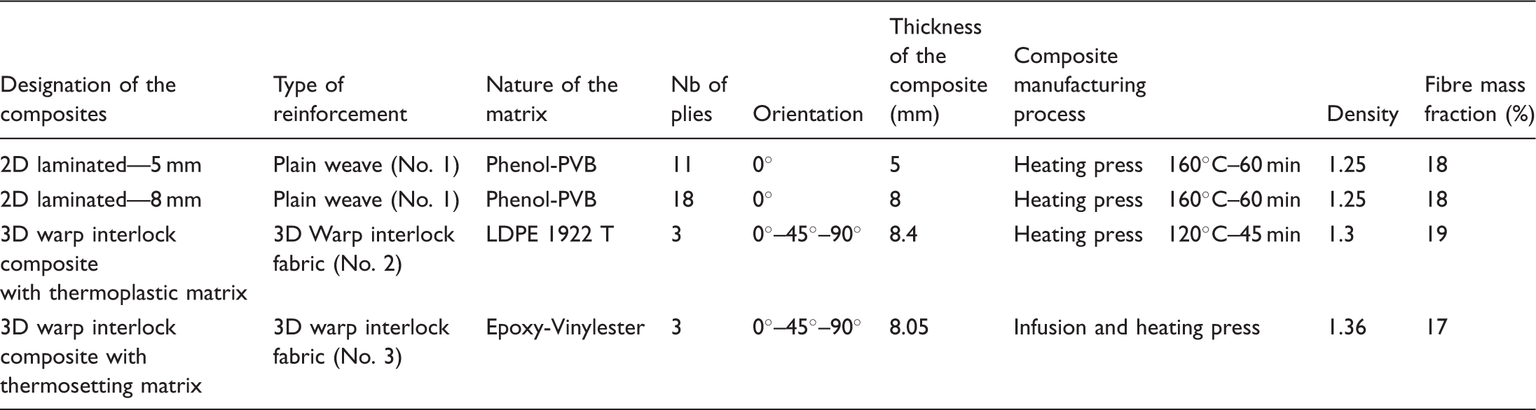
Technical data of the three different textile reinforcements.

Technical data of the four manufactured composites.
This composite, the benchmark of our study due to its widespread use in hard ballistics, has been manufactured with two different thicknesses.
3D warp interlock composite with thermoplastic matrix
The third type of composite is a 3D warp interlock composite designed and manufactured at GEMTEX laboratory. The main characteristic of the 3D warp interlock fabrics is their bonding between plies created by the specific evolution of given warp yarns going through the fibrous structure [25].
The warp yarns are made up of a para-aramid yarn while the weft yarns are composed of para-aramid yarns blended with a low-density polyethylene (LDPE) multi-filaments (see Figure 4).
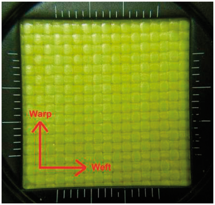
Schematic view of the double-blended yarn. View of the surface of the 2D-laminated composites (5 and 8 mm).
The para-aramid yarn, which is a commercial product, and the LDPE yarn, which is manufactured within our own laboratory are assembled on a conventional twisting machine.
This double-twisted yarn technique is used, because the LDPE cannot be inserted alone during the weaving process but also to ensure the proper distribution of the thermoplastic matrix within the composite structure thickness.
Three plies of this 3D warp interlock fabric with thermoplastic matrix are assembled under high temperature and pressure. When the temperature of the heating-press reaches 120℃, the polyethylene melts and builds up the matrix of the composite (see Figures 2 and 6 and Tables 1 and 2).
View of the surface of the 3D warp interlock composite with thermoplastic matrix.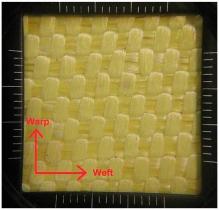
3D warp interlock composite with thermosetting matrix
The fourth type of composite is made up of the same 3D warp interlock fabric architecture previously introduced, but manufactured only with an aramid yarn in warp and weft directions.
Three plies of this fabric are assembled according to an infusion methodology.
After the thorough infusion of the textile reinforcement and before the matrix started polymerizing, the resulting composite is compacted into a non-heated high pressure press in order to reach the expected thickness and amount of resin in the final composite (see Figures 2 and 7 and Tables 1 and 2).
View of the surface of the 3D warp interlock composite with thermosetting matrix.
It is important to note that the three composite structures have been designed in order to present the same thickness as well as a similar amount of resin in the composite in order to be compared with each other. Indeed, the mass of the matrix in the 2D-laminated composite represents 18% of the composite final mass. For the thermoplastic 3D warp interlock composite, this ratio is 19%, and the manufacturing process of the 3D warp interlock composite with the heat-hardening matrix has been controlled in order to reach 17%.
The low resin amounts within those composites compared with the fibrous reinforcement allow a higher deformation capacity of the composite under mechanical stresses.
Experimental study
High-speed impacts have been carried out according to the STANAG 4569 norm-referenced test.
A 54-g cylinder-shaped steel projectile is accelerated, via powder gun, to a high velocity of up to 1000 m/s.
The projectile perpendicularly impacts an armoured shield made up of a metal alloy plate and a textile backing made up of two parts (a first 8 mm part and a second one of 5 mm).
The three elements of each target (metal plate, first part of the backing and second part of the backing) are bolted together on a square 160-mm shooting frame (each element of the target is 300 mm long) (see Figure 8).
Assembly of the different elements of the target.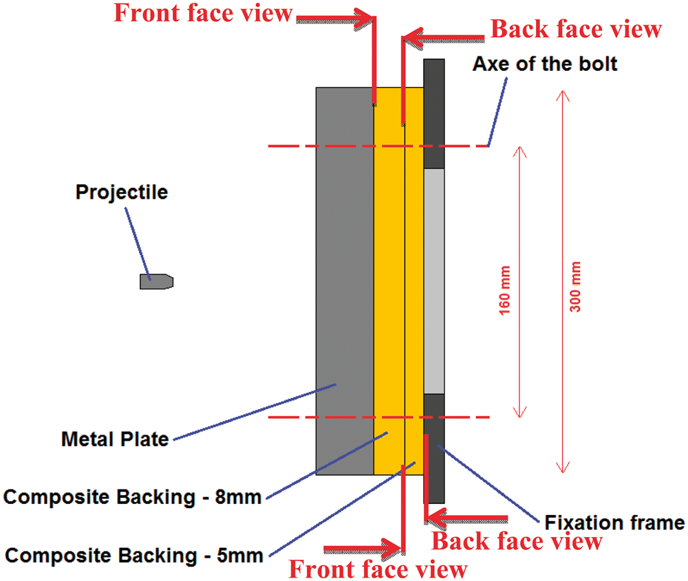
Every configuration of target was tested with only one shot for a given velocity. However, for a given target configuration, three different velocities were tested in order to determine the minimum interval between the no perforation and perforation velocities. Thus, taking into account this approach, proposed by our industrial partner, the average velocity calculated from the no perforation and perforation velocity has been assumed to be the perforation limit velocity. A wider number of impact tests seems to be necessary to obtain a more accurate value of the perforation limit velocity and can be performed in future works. Considering the funds and time of this research project, the number of impact tests and targets to produce has been limited. Thus, the main aim of this research project was not oriented to find the exact perforation limit velocity but to evaluate the different impact behaviours of several textile composite configurations submitted to the same impact velocity. Given the fact that this impact study deals with military issues, some geometrical information as well as exact velocity is not disclosed on the demand of our industrial partners. Nevertheless, the thickness and the nature of the metallic part remain constant in every tested configuration. The thicknesses of both composite parts are a dimensional constraint defined by the manufacturer who is willing to test every composite in the same configuration as his benchmark product.
In order to understand the combined influence of the textile architecture coupled with the moulding process, we have decided to test our composite using three different combinations.
The three configurations are summarised in the following:
First configuration: this backing solution is a full 2D-laminated sheets. The first part is a 2D 8-mm thick laminated and the second part a 2D 5-mm thick laminated (see Figure 9). Second configuration: this backing solution is a combination of 8 mm thickness of 3D warp interlock composite (thermoplastic matrix) and 5 mm thickness of 2D-laminated composite (see Figure 10). Third configuration: this is a combination of 8 mm thickness of 3D warp interlock composite (heat-hardening matrix) and 5 mm thickness of 2D-laminated composite (see Figure 11). Schematic of the first configuration. Schematic of the second configuration. Schematic of the third configuration.
Measurements of the projectile velocity before and after impact have been performed, thanks to several X-ray devices. Those three configurations were tested in the case of a high-velocity impact, of up to 1000 m/s, and different types of impact behaviour can be observed, especially in terms of protection. Because of the restriction concerning the indication of the perforation limit velocity, we have decided to compare in this paper the results reached by the different configurations when the three of them were impacted at the same velocity.

The experimental results are presented below.
Experimental results
First configuration
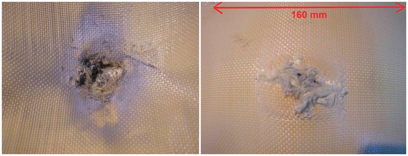
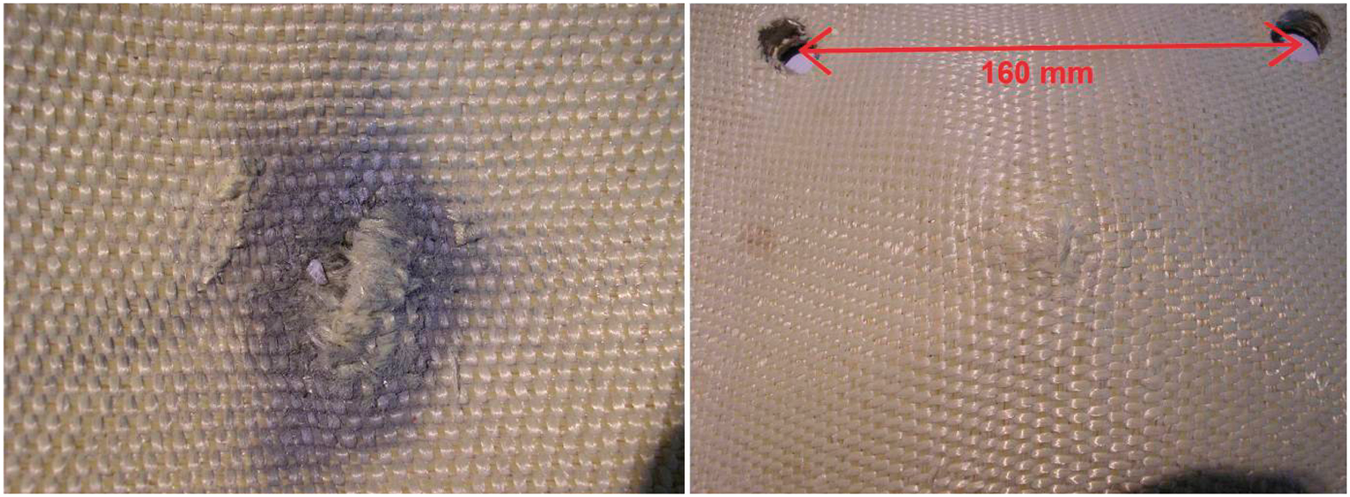
The first configuration has stopped the projectile. The first part of the backing (8 mm) is entirely perforated and shows a significant 48-mm back-face deformation depth. A significant damaged area is also observed (see Figures 12 and 13). On this part of the backing, we can observe that the warp and weft yarns of the fabric were more damaged at the impact point since all yarns in this area were broken under shearing stress, forming the typical cross-shaped damage area on the fabric.
View of the first part (8 mm thick—2D-laminated composite) of the configuration no. 1. Front face of the 8-mm thick composite (left picture) and back face (right picture).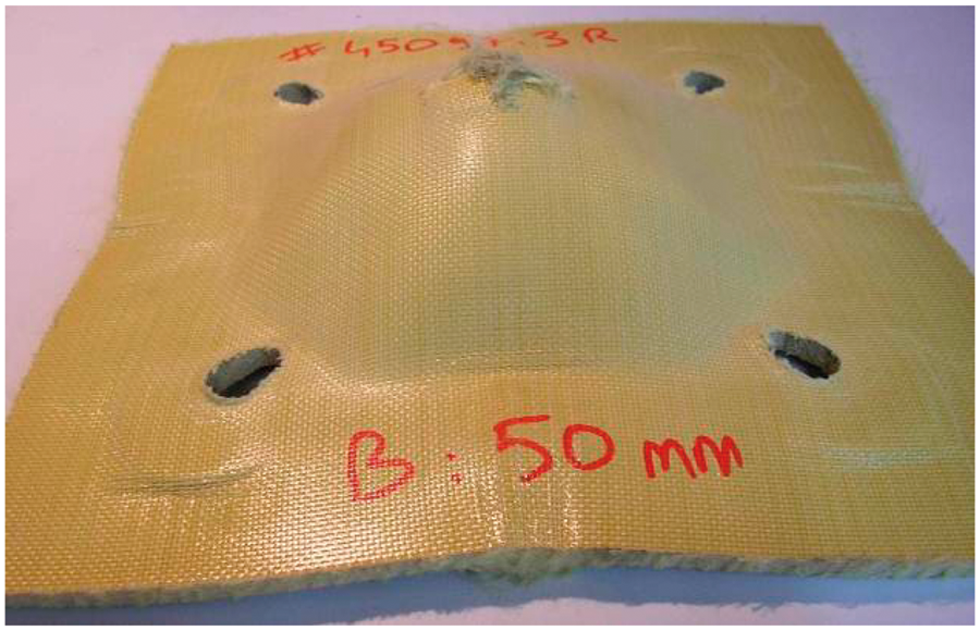
The second part of this backing (5 mm) displays a 49-mm back-face displacement; nevertheless, this part of the backing still remains unperforated (see Figures 14 and 15). It is possible to observe a very similar behaviour on both parts of the backing since they are made of the same material. Indeed, both parts show the same deformation shape and tend to react as a single and entire part.
View of the second part (5 mm thick—2D-laminated composite) of the configuration no. 1. Front face of the 5-mm thick composite (left picture) and back face (right picture).

A cross-section of impacted samples was performed via high-pressure water jet cutting. This technique makes it possible to cut resistant materials by applying a huge pressure effort onto a very localised area of the sample, so that no deformation is observed after the cutting operation.
The cross-sectional view of this backing allows us to observe some delaminations within the structure. This failure mode, generated by layer splitting up, is representative of the rupture mode of a laminated composite under impact load (see Figure 16) [26].
Cross-sectional view of the first configuration after impact.
The deformations of both parts of the composite are significant in terms of depth, although the damage is localised close to the projectile. A careful analysis of the damage localised on the first part of the backing reveals that it is due to shear stress under compression.
The second part of the backing remains un-perforated, even if it can be possible to observe the beginning of a tensile fibre breakage on the back-face of the composite, due to significant tensile stress generated by the dynamic deformation (see Figure 15).
Second configuration
The second configuration has also stopped the projectile, although presenting more considerable deformation. The first part of the backing (8 mm) is partially perforated; indeed, the projectile has perforated two of the three layers of the composite structure. The back-face backward motion is 48 mm in height (see Figures 17 and 18).
View of the first part (8 mm thick—3D warp interlock composite) of the configuration no. 2. Front face of the 8-mm thick composite (left picture) and back face (right picture).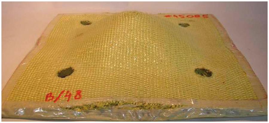
The second part of the backing (5 mm) remains un-perforated although it still presents a considerable 57-mm deformation depth (see Figures 19 and 20).
View of the second part (5 mm thick—2D-laminated composite) of the configuration no. 2. Front face of the 5-mm thick composite (left picture) and back face (right picture).

It can be observed that both parts, featuring different thicknesses and architectures, but made up of the same raw material, do not present the same residual deformation.
Indeed, the first part, the 3D warp interlock composite, shows a more flexible behaviour, thanks to its thermoplastic matrix and manufacturing process resulting into a smaller residual deformation. This residual deformation is different from the maximum deformation that the composite reaches during the dynamic loading.
The residual deformation of the last part, the 2D-laminated composite remains more significant since the material is more rigid.
On the cross-sectional view, it can be observed that this difference of rigidity generates a gap between the two parts of the backing (see Figure 21).
Cross-sectional view of the second configuration after impact.
The damages and mode of rupture of the fibres on the impact area suggest that the first two plies of the 3D warp interlock composite had to cope up with a mix of shear and tensile stresses.
Those two plies, which remain together, display a smaller residual deformation than the third one.
The third ply had to cope up mainly with tensile stress, causing a delamination in the composite between the first two and the last structure plies.
We can observe the beginning of tensile fibre breakage on the back-face of the composite, which means that the 2D-laminated composite has reached its maximum deformation during the impact (see).
Third configuration
The third configuration has been perforated, and the residual speed of the projectile still remains high after the perforation of this backing.
A wide damage area reveals that yarns have been torn away from the structure. This first part of the backing (8 mm) presents a tiny deformation (see Figures 22 and 23).
View of the first part (8 mm thick—3D warp interlock composite) of the configuration no. 3. Front face of the 8-mm thick composite (left picture) and back face (right picture).

The second part of the backing (5 mm) is perforated and presents a smaller perforation hole than the one that can be observed on the first part (see Figures 24 and 25).
View of the second part (5 mm thick—2D-laminated composite) of the configuration no. 3. Front face of the 5-mm thick composite (left picture) and back face (right picture).

On the cross-sectional view, we can observe that this part shows a resulting hole corresponding to the exact size of the projectile (see Figure 26).
Cross-sectional view of the third configuration after impact.
The failure of the composite appears as a sharp break, and the rupture of fibres is also straight, which means a pure shearing stress during the impact, especially for the first two plies of the composite that remain together and show a small backward motion.
The third ply has to cope up with both shear and tensile stresses, resulting in a higher deformation and delamination between the first two plies and the last one.
The back-face deformation depth of this material, which is the smallest, recorded in this study, is 34 mm. This value reveals the low deformation ability of the composite during impact and the very stiff properties of this composite.
The second part of the backing (5 mm), the 2D-laminated composite, presents a smaller hole. The level of the damage occurring at the back-face is still high although more localised. The characteristic fibre breakage on the perforation area shows that the composite fails under the considerable tensile stress further demonstrated by yarns being pulled out of the structure.
The maximum back-face deformation of the second part is 49 mm height, which is significant, given the fact that the 2D-laminated composite presents a more flexible behaviour compared with the thermosetting composite (see Figure 26).
Discussion of results
This study has revealed that textile composite backings display different behaviours under the same impact according to the different combination and nature of the protective solutions.
The first observation reveals that the nature of the matrix is one of the key factors. Indeed, we can establish that the third configuration is ill-adapted to the threat, since the backing failed to ensure full protection and was thoroughly perforated. This result can be attributed to the very stiff behaviour of the 3D warp interlock fabric with the thermosetting matrix. After polymerization, the composite is completely constrained and therefore not flexible. This rigidity is highly inappropriate since it does not allow to absorb the necessary amount of energy released during the deformation of the backing.
The second and third configurations, which present the same textile reinforcement but a different matrix, provide very different results under high-velocity impacts. The thermoplastic matrix tends to allow the necessary deformation while the thermosetting matrix tends to break at the beginning of the impact.
The second observation is the importance of the fibrous reinforcement nature. During the test campaign previously described, both first and second configurations encapsulated the projectile. Indeed, in the first configuration, the 2D pre-impregnated laminates show a first perforated 8 mm part, while the second 5 mm part remains un-damaged. Considering the second configuration, the 3D warp interlock fabric impregnated with a thermoplastic matrix reveals a partially 8 mm perforated first part and an entire 5 mm un-damaged second part.
This interesting behaviour of the 3D warp interlock fabric with the thermoplastic matrix when compared with the 2D-laminated composite solution can be explained by the improved flexibility of the fibrous reinforcement. Indeed, the evolution of yarns in terms of thickness, coupled with the non-systematic bonding of yarns on a same layer, tends to provide a more deformable structure than a similar composite made of 2D pre-impregnated laminates.
Beyond the nature of the fibrous reinforcement and of the resin, the composite manufacturing process is also an important parameter. It is possible to observe on samples after impact tests, that when the matrix is built-in during the manufacturing process, as in the first configuration (the matrix is laid down on the fabric top surface) and also in the case of the second configuration (the matrix is incorporated within the textile structure as a yarn), the resin does not fully penetrate the fibre. The thick nature of the matrix in both processes does not allow a deep penetration of the resin within the fibre, allowing motion and deformation of the fibrous reinforcement and resulting in a flexible composite.
The third configuration was manufactured according to a conventional resin transfer moulding process (RTM). Here, the matrix is incorporated later on into the fibrous reinforcement, implying a lower resin viscosity value to allow its impregnation through the textile. This liquid resin is distributed around the yarns and induces a deep penetration into the core of the fibre. This deep impregnation does not allow any fibre motion and tends to prevent any deformation of the resulting composite. This observation can be made on the third configuration, where the high-fibre impregnation due to the RTM process conferred to the composite a very stiff behaviour leading to a brittle rupture.
Those conclusions concerning the composite manufacturing process should be limited to the tested materials, and a more complete study would be necessary to draw wider conclusions.
Deformations can be observed on the composite at the fixation screws level where bearing phenomena occurred. Those deformations mean that a part of the impact energy has been transmitted to the fixation. This phenomenon was observed but not detailed and can be studied to optimise the 3D reinforcement architecture in order to increase the energy absorption capacity of the backing.
The choice of the different backing parameters such as the resin, the manufacturing process and the structure of the textile reinforcement is paramount in order to reach the expected and safe level of protection against high-velocity impacts.
Conclusion
Both first and second configurations succeeded to stop the projectile while the third configuration has been completely destroyed by the ballistic testing, since the target was perforated.
The second configuration presents an important delamination between the integral plies of 3D-woven composites. However, only one delamination can be observed on the 3D composite between the first two and the last plies.
The delaminations are much less pronounced in the case of the first configuration; they are nevertheless more numerous.
The better overall integrity of the first configuration is due to the fact that this target is composed of only one type of composite material, so both composite plates react to impact in the same way.
However, this study is only focused on the level of protection provided by the different configurations in the case of a single impact, so the only parameter investigated here is the damage in terms of perforation depth. Thus, the second configuration, using 3D warp interlock fabric as reinforcement, impregnated with a thermoplastic matrix reached for this study show the best level of protection of this comparison since it was the least perforated.
This study reveals that it is possible to upgrade the level of protection of an armoured solution without increasing the mass of the components but only by enhancing the impact behaviour of the composite parts.
The promising results obtained show the necessity to work on the improvement of the backing parameters. Additional studies to improve the parameters of the composite would certainly enable to stop projectiles with even higher impact velocities.
As a result, some studies are in progress, in order to develop backings fully made up of 3D warp interlock composite impregnated with a thermoplastic matrix but also to have a better understanding into the influence of the different composite parameters. Those developments aim at improving the properties of the backing and developing more efficient products.
Footnotes
Funding
The authors thank ISL for carrying out all the impact tests and NEXTER SYSTEMS for providing advice and funds to conduct this research.