
Abstract
As a widely used thermal protection material for the aerospace vehicle, needled composites cannot avoid the impact load of the external environment during flight or reentry process, but the lack of continuous reinforcing fibers in the thickness direction results in weak impact resistance. In order to improve impact resistance property, this paper proposed a new type of needled/I-fiber coupling reinforced composite structure and carried out impact characteristics research. First, the needled/I-fiber coupling reinforced preforms and composites with different I-fiber stitching parameters were prepared; further, the impact tests of needled/I-fiber coupling reinforced composites were carried out, and the damage area and bulge height after impact were measured. Finally, the compressive strengths after impact were tested and analyzed. The research results showed that I-fiber absorbed the impact energy and effectively inhibited the delamination propagation of the needled/I-fiber coupling reinforced composite during the impact process. The damage area and bulge height of the needled/I-fiber coupling reinforced composite were reduced by up to 46.5 and 46.02% respectively. Moreover, the compression strength after impact increased by up to 17.6%. Our work may provide a simple and effective method for improving the impact resistance of needled composites structure for aerospace vehicle.
Keywords
Three-dimensional (3D) textile composites have been widely used in high-tech fields such as aerospace, national defense, and rail transit.1–3 The 3D needling technology has a high degree of automation and low production cost. In recent years, the structure and properties of 3D needled fabrics and composites have been a hot research topic. 4 Ishikawa T et al.5,6 reconstructed the structure of the needled fiber mat by X-CT under the conditions of non-destructive testing, and quantitatively analyzed the needled fiber bundles in the Z direction, and the quantity relation between the needling processes, fabric structure and in-plane tensile property. The three-dimensional needling forming process is complicated. Xie J et al. 7 proposed a numerical simulation research on needling forming process on account of the fictitious fiber model, and intuitively revealed the interaction mechanism between the needle and the base cloth and the felt. Chen X et al.8,9 used quartz felt/woven cloth as the laminated unit to study the forming methods of different configurations of curved needled fabrics, and discussed the influence of different base cloth structural parameters on fabric formability. Recently, Yao T et a1. 10 proposed a new type of none-felt needled fabric structure which improved interlayer and in-plane performance greatly.
In terms of 3D needled composites, researchers have established a variety of meso-level finite element analysis models based on the structural characteristics of needled composites. Meng S et al. 11 presented a representative unit cell based on fiber to forecast the elastic constants of 3D needled carbon-carbon (C/C)composites using a lamination modeling method. Needled composites often contain void defects, a finite element analysis model considering random defects was established by Han M et al., 12 and the flexural strength and modulus of C/C needled composites was predicted, the predicted results were highly consistent with the experimental results. The tensile and compression damage evolution model13,14 and the effect of pinhole dimensions and scatter on the stress concentration 15 of 3D needled composites were also studied. Moreover, Xie J et al.16,17 analyzed the nonlinear mechanical behavior of 3D needled C/C-SiC composites by using the combined elastic-plastic damage model, the nonlinear stress-strain curves for the composite under off-axis tensile and shear loadings could be accurately described by the model.
At the same time, researchers have conducted a large number of studies on the compression, tensile, bending properties, and damage evolution process of needled composites through different experimental methods.18–20 Wan F et al. 18 used X-CT and DVC in-situ observation techniques to study the compression damage evolution process of needled C/SiC composites, and found that cracks existed within the microstructure before the application of load, due to thermal strains, and their propagation was affected by the heterogeneous microstructure and the direction of loading. The needled carbon fibers were observed to restrict the propagation of damage. The tensile behavior of C/SiC needled composites under cyclic loading was analyzed by Liu Y et al. 19 And Zhao W et al. 20 researched the influence of carbon fiber felt content and fiber orientation on the mechanical properties and thermal performances of carbon fiber/PEEK needled composite. Moreover, Sachin Tejyan et al.21–23 studied the physico-mechanical and erosive wear behaviour of polyester fibre-based needled nonwoven fabric mat reinforced epoxy composites, results indicated that the increase of fiber content enhanced the physical and mechanical properties of the composites. Needled composites are widely used as thermal protection materials for thin-walled cabin of aerospace vehicle, and cannot avoid the impact load of the external environment during flight or reentry process. Perforation of needle-punched carbon-carbon composites during high-temperature and high-velocity ballistic impacts was researched by Xie W et al., 24 results showed that needled composite panels had a lighter mass while absorbing the same energy compared with Inconel panels. As the flying speed of aircraft increases, higher requirements are put forward for the lightweight and impact resistance of existing needled thermal protection materials. Stitching is an effective method to enhance the through-thickness performance of composites, including lock stitching, modified lock stitching, chain stitching25–27 and I-fiber stitching.28–30 Compared with other stitching methods, the I-fiber implantation method can realize the implantation of brittle fibers without damage to the fibers, and has a high degree of automation, high efficiency and low cost.
This paper proposed a new type of needled/I-fiber coupling reinforced impact-resistant composite and the impact characteristics was studied. The needled/I-fiber coupling reinforced preforms and composites with different I-fiber stitching parameters were prepared. The impact tests of needled/I-fiber coupling reinforced composites were carried out, and the damage area and bulge height after impact were measured. At last, the compressive strengths after impact were tested and analyzed. This paper may provide a simple and effective method for improving the impact resistance of needled composites.
Manufacture of test sample and impact test
Preparation of needled/I-fiber coupling reinforcing preform
Specification of quartz materials.


Schematic of needled/I-fiber coupling preform manufacturing process.
The needling robot8–9 and I-fiber implantation robot
10
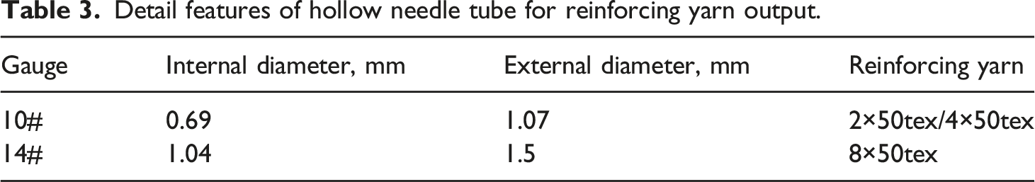
are displayed in Figure 2. The I-fiber implantation robot for preparing the needled/I-fiber coupling preform was independently developed by Tiangong University. The implantation of I-fiber yarns of different scales required different hollow needle tubes to ensure the smooth transmission of I-fiber yarns, and the internal diameter of the input needle tube needed to be less than that of the output needle tube. In addition, the heads of the input needle tube were flat and the head of the output needle tube were sharp. Tables 2 and 3 summarize the detailed parameters of the hollow needle. The needle tubes were standard injection needles. Robots for needled/I-fiber coupling preform manufacturing. (a) Needling robot; (b) I-fiber implantation robot; (c) hollow needle tube. Detail features of hollow needle tube for reinforcing yarn input. Detail features of hollow needle tube for reinforcing yarn output.

Experimental design of I-fiber stitching for needed preforms.

Manufacture of needled/I-fiber coupling reinforced composite
The needled/I-fiber coupling preform was compounded into composite by Resin Transfer Molding (RTM) process. TDE-86 epoxy resin (4,5-epoxycyclohexane-1,2-diglycidyl diformate) produced by Tianjin Jindong Chemical Composite Material Co, Ltd was used as the matrix of the needled composite plates. The catalyst was N, N-dimethyl benzylamine and the curing agent was methyl tetrahydrophthalic anhydride. The mixture ratio of resin, curing agent and catalyst was 100:125:0.8.The size of composite slab was 380 mm*180 mm*4 mm. Samples of 150 mm×100 mm needled/I-fiber coupling reinforced composite for the impact experiment were produced according to ASTMD7136. The geometry of the impact sample and the reinforcement location for per stitching point are shown in Figure 3. The thickness of all samples kept 4 mm and the thickness had little variety during RTM compounding. Figure 4 shows the detailed procedure of composite fabrication. Geometry of impact sample and I-fiber stitched pattern. The detailed procedure of composite fabrication.

Impact test
As showed in Figure 5, a drop hammer impact test machine (Instron Dynatup 9250HV) was used for the impact experiment. During the impact test, the instrument can obtain the impact load and the energy by the halfsphere shape impactor with a load cell. The diameter of the hemispherical drop hammer was 12.7 mm. The anti-secondary impact device was adopted to avoid the secondary impact caused by the falling hammer to the samples again. Load-time curve, energy-time curve and characteristic value of impact mechanical property could be obtained. Impact test instrument.
According to ASTM D7136, 6.7 J of impact energy shall be exerted to each 1 mm thickness samples. The thickness of the impact samples prepared was 4.0 mm, so 26.8 J of impact energy should be applied to the test samples. equation (1) can be used to calculate the impact energy E without any loss. During the impact test, the mass of the impactor was 7.2940 kg and the drop height of the impactor was 330 mm.
The representative energy-time diagram of sample for the impact test is shown in Figure 6. Eimpact, and Eabsorbed can be obtained from this graph. E impact and E absorbed respectively represent the total impact energy exerted to the samples and the energy absorbed by the samples during the impact process, and the latter was related to the failure of the reinforcing fibers, delamination and matrix cracking. Table 5 shows the impact energies and absorbed energies of all samples in the impact test. It can be seen from Table 5 that the tested impact energies were practically the same as that counted through equation (1). In addition, the energies absorbed by the unstitched samples was roughly identical to the energies absorbed by the stitched samples. Therefore, it can be considered that the energy absorbed during the impact process had little relationship with the implantation of I-fiber. While the damage area and the bulge height of damage after impact actually depended on the I-fiber implant pattern. Representative energy-time diagram for unstitched (a) and stitched specimen (b). Impact energies and absorbed energies in the impact test.

Figure 7 displays the measurement of impact force-time of the needled/I-fiber coupling reinforced composite panels, and the curve tendency of the unreinforced samples and the reinforced samples was almost similar. It can be seen from Figure 7 that the impact load increases with time until the load suddenly drops to a static value Fr, then increases the load again until reaches the maximum load Fmax, and the Fr was also identified as the critical force Fcr. It was widely known that the initial delamination of composites occurred at the critical force Fcr, and the drop of the bending stiffness of the needled composite plates after delamination leaded to a sudden decrease of load. Representative force-time diagram for unstitched specimen (a) and stitched specimen (b).
The measurement of critical force Fcr of the needled/I-fiber coupling reinforced composite panels is shown in Figure 8. The bars at the bottom and top respectively represented the minimum and maximum values tested in each case. It can be seen from Figure 8 that the critical forces of the needled composite panels without stitched were slightly higher than those of the needled/I-fiber coupling reinforced composite panels. It can be concluded that the delamination began from the damage produced around the stitched hole through the stitching process, and that the critical forces of the same reinforcing area density samples were floating due to the effect of the impact position and the I-fiber head, but in general, the stitching damage resulted in a reduction in the critical forces. The value of Fcr was determined by the combined effect of the reinforcing area density, the implant pattern and impact position. In addition, under the same implant pattern, the larger the reinforcing area density, the smaller the Fcr. Critical forces of the test samples. (a) 1.44% reinforcing area density; (b) 2.88% reinforcing area density.
The representative load-deflection curve for estimating the flexibility of the needled/I-fiber coupling reinforced composite plates is shown in Figure 9. The curve forms of the reference samples are the nearly same as needled/I-fiber stitched samples. Figure 10 shows that all maximum deflections of the samples showed nearly the same values. The above results indicated that little change in bending stiffness as the implantation of I-fiber. The I-fiber stitching had less effect on the in-plane properties of the needled composites as needling had already caused great damage to the in-plane property. Representative load-deflection curve of unstitched and stitched samples. Maximum deflections of the test samples. (a) 1.44% reinforcing area density; (b) 2.88% reinforcing area density.

Measurement of damage area and damage bulge height
After the impact test, the ultrasonic C-Scan nondestructive machine (BSN-C3409)was used to survey the damage area of every needled composite plates, as shown in Figure 11(a). Pro Plus image software was used to calculate the damage area of samples after impact. The typical C-Scan pictures of different parameters are shown in Figures 11(b) to (f). Representative C-Scan images of composite panels of different parameters. (a) Test set-up for C-Scan test; (b) Case1; (c) Case2; (d) Case3; (e) Case4; (f) Case5.
Cracks were observed when impact energy of 26.8 J was exerted to the samples, and a large proportion of the damage area was appraised to be less than 50 mm × 50 mm. Hence, it was reasonable to estimate the impact resistance of the needled/I-fiber coupling reinforced composite with the reinforcing area of 50 mm × 50 mm. Because the needled fiber bundle and I-fiber strengthen the interlaminar property of the composite, the damaged area did not form a 45° angle failure like the laminated composite, but approximated an elliptical shape. Moreover, the damage area was obviously related to the I-fiber stitching pattern and reinforcing area density.
The damage areas of the needled/I-fiber coupling reinforced composite panels are shown in Figure 12. Compared with unstitched needled composite panels, the damage area of reinforced composite panels reduced by 14.75–46.50%. The damage area of the needled composite plate with 1.44% reinforcing area density and 2.88% reinforcing area density are exhibited in Figures 12(a) and (b), respectively. It can be seen from Figure 12(a) that the narrower the interval, the smaller the damage area, in addition, the damage area of the Case 2 (the narrowest interval) is reduced by 36.3% compared to the needled without stitching composite panel. According to the identical stitching intervals (Case 2/5), it can be concluded that the stitching density increased, the damage area decreased. The smallest damage area of the Case 5 was reduced by 46.5% compared to the needled composite. I-fiber absorbed the impact energy and effectively inhibited the delamination propagation of the needled/I-fiber coupling reinforced composite during the impact process. Damage area of the test samples. (a) 1.44% reinforcing area density; (b) 2.88% reinforcing area density.
The damage bulge height of each composite panel was measured by the profiler test machine (T-3000, Hitachi), as shown in Figure 13(a). Representative damage bulge images of the composite panels are shown in Figures 13(b) to (f). The contour of the impact damage bulge presented a volcanic shape. Representative damage bulge images of the test samples. (a) Profiler test machine; (b) Case1; (c) Case2; (d) Case3; (e) Case4; (f) Case5.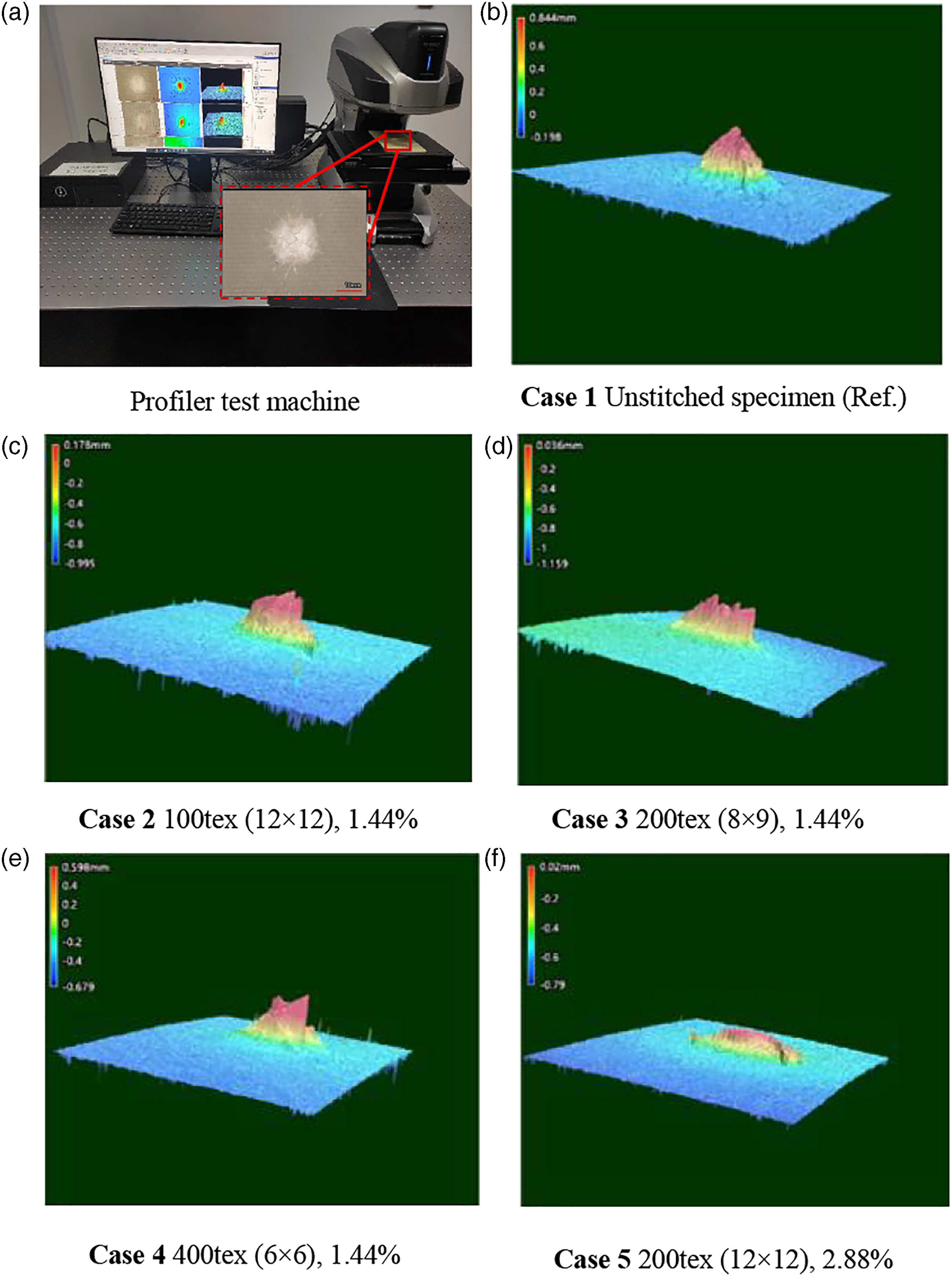
Figure 14 presents the average damage bulge height of the I-fiber stitching composite panels. Compared with the needled composite panel without stitching, the damage bulge height was reduced by 26.77–46.02%. The same as the law of area damage, the smaller the stitching interval, the smaller the height of the damage bulge; the greater reinforcing area density, the smaller the height of the damage bulge. A cross-section of the needled/I-fiber coupling composite panel after the impact test is presented in Figure 15. It can be seen from the Figure 15 that the failure modes of needled/I-fiber coupling composite included I- fiber fracture, matrix fracture, warp or weft yarn fracture, and delamination propagation. When the I-fiber closest to the impact point was broken, the I-fiber absorbed impact energy meanwhile the propagation of the cracks was prevented, and so the damage area and the damage bulge height of the needled/I-fiber coupling reinforced composite plate was reduced. Damage bulge height of the test samples. (a) 1.44% reinforcing area density; (b) 2.88% reinforcing area density. Cross-section of the needled/I-fiber coupling composite plate after the impact test.

Compression after impact test
Compression tests were performed after second impact in reference to ASTM D7137. The universal test machine (AG-250 KN, SHIMADZU Co) and DIC measuring system (ARAMIS, GOM Co) were used for test, and the loading speed was set at 1.25 mm/min during compression. Figure 16(a) shows a diagram of the CAI test instrument. According to the experimental data, the residual compression strength of the specimen after impact was calculated according to equation (2).
31
Test set-up for compression after impact (a) and representative load-deflection curve for unstitched and stitched samples (b).
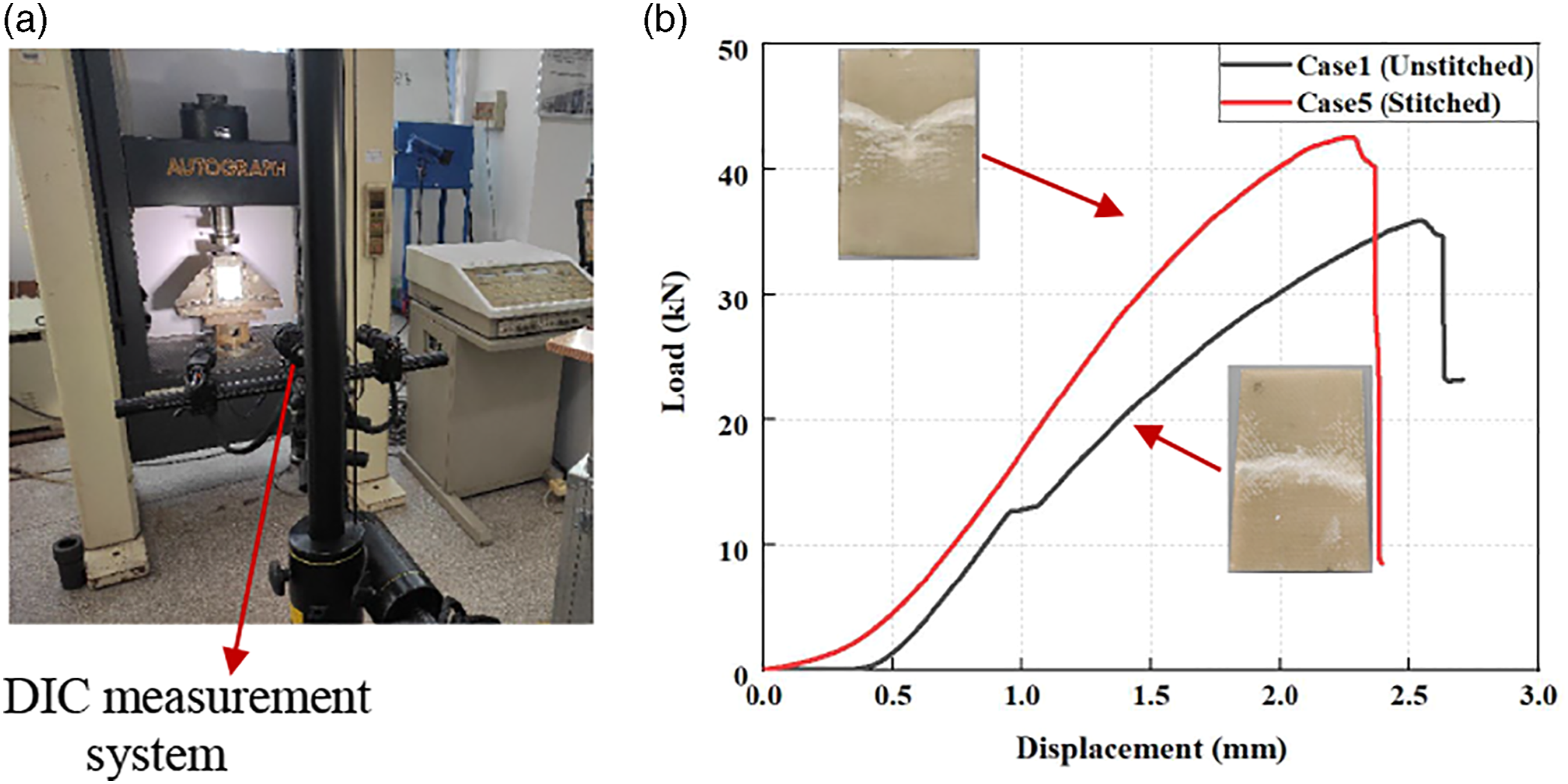
Figure 16(b) shows the representative load-displacement curve for control group and experimental group. When the compressive load reached maximum value, the specimen broken and the load suddenly dropped. Needled/I-fiber coupling reinforced composite achieves higher compressive failure load value after impact. Figure 17 shows the specific value of the maximum failure load. As shown in Figure 18, strain distribution nephogram of specimen during CAI is presented. The strain of the entire panel was concentrated and released at the impact area. With the further increase of the load, the longitudinal cracks of the composite panel no longer increased, but the cracks extended along the transverse direction until the panel was completely destabilized and fractured. Due to the reinforcement of I fiber, the entire stitched area presented a relatively uniform strain, and the crack propagation in the impact zone was slower compared to the unstitched needled panel. The failure strain of needled/I-fiber was less than that of unstitched needled composite. The maximum failure load of CAI. (a) 1.44% reinforcing area density; (b) 2.88% reinforcing area density. Strain distribution nephogram of specimen during compression after impact. (a) Unstitched specimen; (b) stitched specimen (Case 4).
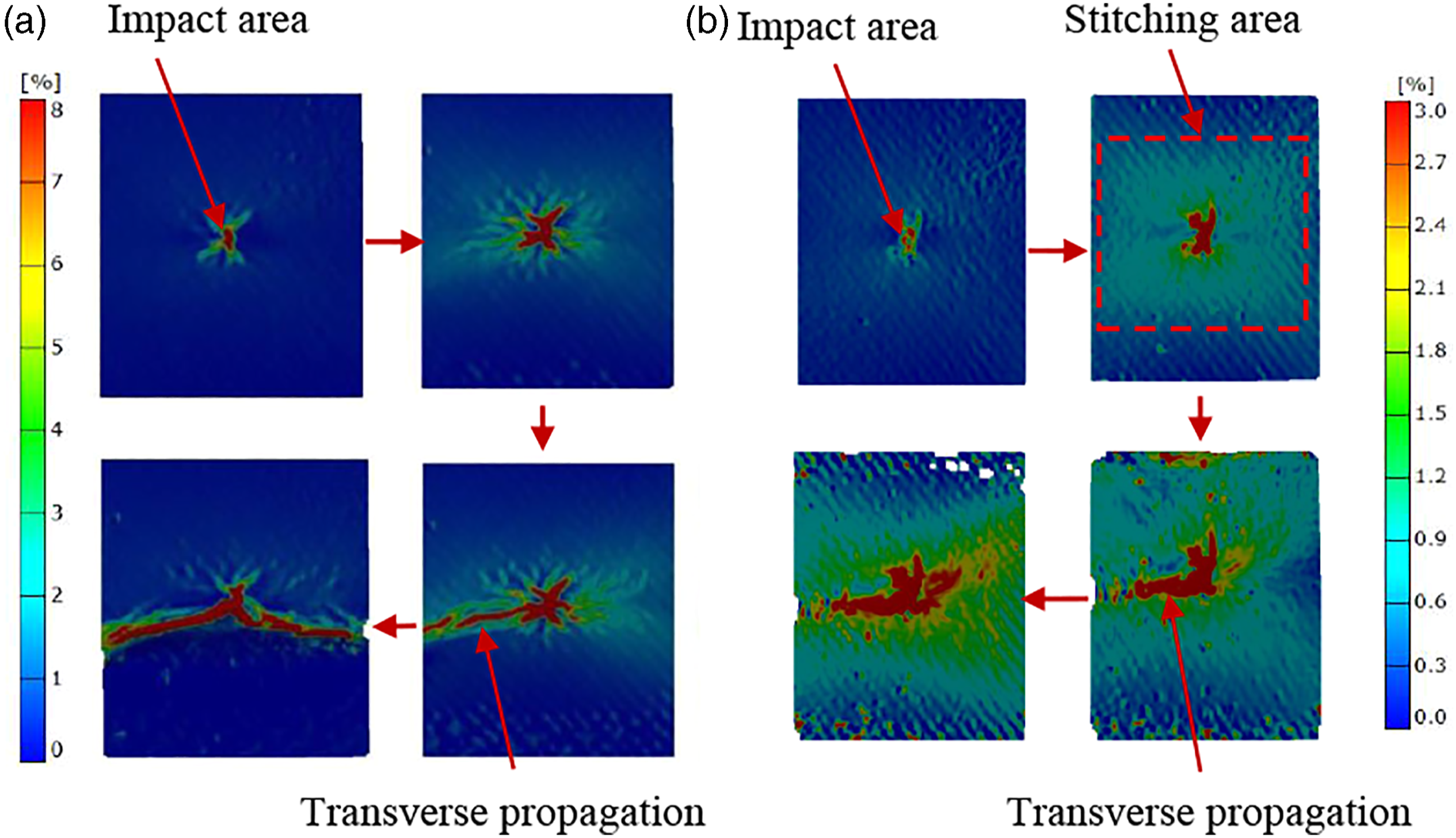
Figure 19 shows the compression strength after impact (CAI). Compared to those needled composite panels without stitching, the CAI of the needled composite plates with 1.44% reinforcing area density increased by 5.65–8.33%. When the reinforcing area density was 2.88%, the CAI was increased by 17.60%. It can be found that the larger I-fiber reinforcing area density, the higher the CAI performance. As shown in Figure 20, it was further proved by impact test and CAI test that the damage area and damage bulge height were inversely proportional to the compressive strength. Compression strength after impact of the test samples. (a) 1.44% reinforcing area density; (b) 2.88% reinforcing area density. Compression strength after impact against damage area (a) and damage bulge height (b).

Conclusions
From the impact test and the CAI test of the needled/I-fiber coupling reinforced composite, the following conclusions can be got. First, I-fiber absorbed the impact energies and effectively inhibited the delamination propagation of the needled composite during impact process. Then the damage area of the needled/I-fiber coupling reinforced composite was reduced by 14.75–46.50% compared to the unstitched needled composite. And the damage bulge height of the needled/I-fiber coupling reinforced composite was reduced by 26.77–46.02% compared to the needled composite. With the same reinforcing area density, the narrower the stitching interval, the smaller the damage area and damage bulge height. The CAI of the needled composite plates with 1.44% reinforcing area density increased by 5.65–8.33%. When the reinforcing area density was 2.88%, the CAI was increased by 17.60%.The larger I-fiber reinforcing area density, the higher the CAI performance could be obtained. And little change in bending stiffness as the implantation of I-fiber. Finally, our work may provide a simple and effective method for improving the impact resistance of needled composite structures for aerospace vehicle.
Footnotes
Declaration of conflicting interests
The author(s) declared no potential conflicts of interest with respect to the research, authorship, and/or publication of this article.
Funding
The author(s) disclosed receipt of the following financial support for the research, authorship, and/or publication of this article: This work was supported by the Scientific Research Project of Tianjin Education Commission (grant number 2018ZD13), Science and Technology Foundation of National Defense Key Laboratory of Advanced Composite Materials (grant number 61429040403), Natural Science Foundation of Tianjin (grant number 18JCYBJC89000), the Tianjin Higher Education Innovation Team Project (grant number TD13-5043) and National Science and Technology Major Project (grant number 2017-Ⅶ-0011–0177).