
Abstract
Lightweight panels are of high relevance for various applications, such as automotive, aerospace, civil engineering, and achieve high stiffnesses and strengths at low self-weight. The sandwich principle is commonly used to manufacture the panels, although conventional materials and reinforcement structures often limit the design and application of the panels in a wide range of possible applications. The reason for this is that lightweight panels fail either under combined compressive/shear loading or as a result of delamination of the individual layers. In this article, novel fabric structures are presented as a basis for the fabrication of lightweight panels that effectively overcome these deficiencies. These fabrics have a spatial truss-like structure, with the core and top layer being connected by continuously running reinforcing fibers. This results in high panel stability and high delamination resistance, which are evaluated in this article using mechanical tests in compression, flexure and combined tension-shear. The results are related to sample panels with conventional honeycomb core as reference. The high potential and excellent delamination resistance of the new fabric-based lightweight panels is shown in the result of the tests.
Keywords
Introduction
Lightweight panels are required in various industries, such as automotive and aerospace fuselage and hood structures, civil engineering, sport goods and highly stressed lightweight structures in general. 1 In relation to their mass, they achieve excellent stiffness and strength and are therefore among the most efficient and important construction methods for lightweight structures. A wide variety of basic materials can be used for their manufacture, so lightweight panels can be very well adapted to the requirements in the respective application. An overview is provided by the studies of Hagnell et al. 2 and Grünwald et al., 3 in which various panel variants based on fiber-reinforced polymers (FRP) are evaluated in terms of their economically efficient use in the automotive and aerospace sector. In contrast to this variety of starting materials, lightweight panels are nevertheless usually constructed from layers bonded together according to the so-called sandwich principle. 4 The stiffness and strength of the lightweight panel results from the combination of thin cover layers of a reinforcing material, e.g., reinforcing fibers or metals, in combination with a core in the center of the panel of low density. Established core materials include polymeric foams, wood and honeycomb cores, e.g., of metal or phenolic resin-impregnated aramid paper. Despite their overall advantageous property profile, various aspects limit the design and application of lightweight panels due to their layered structure. In particular, lightweight panels with foam and honeycomb core are sensitive to locally concentrated compressive and shear loads, 5 causing either local collapse of the core or failure and delamination of the adhesive bond between face sheets and core. Both effects lead to failure of the entire panel and different strategies are needed to improve both compressive strength and delamination resistance.
To improve compressive strength and core stability, a study by Kaya and Selver 6 showed how additional truss-like reinforcing elements can be used to improve compressive strength and shear stability of the core. In further studies, this and similar approaches have been adopted as well, with the core layer made only by such a truss and lattice like structure. Specific approaches exist, for example, using a lattice-like core made of metal sheet (Iftimiciuc et al.) 7 or cellular core structures manufactured additively by SLM (selective laser melting, Maconachie et al.) 8 , as well as core structures made of PLA (polylactic acid)/wood compound manufactured by FDM (fuse deposition modelling, Smardzewski and Wojciechowski) 9 . Other variants are based on the use of FRP (Xiong et al., 10 Schneider et al.) 11 and FRP within a hierarchically built structure (Fan et al., 12 Yin et al.) 13 .
However, the fundamental problem of delamination of the panel layers remains unsolved in the approaches presented, which is due to the purely cohesive joining of the layers along a comparatively small bonding surface between core and face layers. Alternatives exist using textile structures, as these have intrinsic continuous fiber-based reinforcement.14–16 Specifically, with respect to sandwich structures and three-dimensionally formed FRP, textiles enable unique properties in terms of damage tolerance and fatigue resistance. In a study, Brandt et al. 17 compares the mechanical behavior of textile-reinforced FRP with conventional sandwich variants, demonstrating that 3D textile-reinforced FRP exhibit entirely different failure behavior compared to conventional ones and are extremely resistant to the delamination effects that would otherwise be expected. The advantageous properties of textile-based materials and composites are based not only on their mechanical performance, but also on their special thermo-physical properties, as demonstrated by Bedon and Rajčić 18 for example, their use in the construction industry for facade elements and the related applications.
The suitable textile structures for lightweight panels can essentially be categorized as weft-knitted, warp-knitted or woven. For example, Azadian et al. 19 and Turki et al. 20 provide examples of weft-knitted spacer structures for lightweight panels whose cover layers are in the form of separate textile layers that are joined together during the manufacturing process by surface elements also created in the same. In the evaluation and mechanical testing of these structures, it becomes clear that the structure and arrangement of the reinforcing fibers within the weft-knitted mesh structure in particular have a negative effect on the properties of the panels made from them. An approach to remedy this deficit is described by Trümper et al. 21 whereby the developed knitted structures are reinforced by additionally introduced yarn systems with stretched lengthwise and crosswise yarns, thereby achieving significantly better mechanical properties in the FRP. In addition to knitting technology approaches, lightweight panels can likewise be manufactured on the basis of warp-knitting technology, as described in a study by Liu et al. 22 and Yu et al. 23 The extension of these approaches is presented by Franz 24 and Dallmann et al., 25 where the knitted spacer structures have been reinforced by additional yarn systems in analogy to the work of Trümper et al.
In addition, woven spacer structures are used for the development and production of lightweight panels. The subject of various studies are double fabrics with an integrated spacer thread system, the so-called pile threads. In this case, the pile yarns belong to a separate warp yarn system, which is alternately integrated between the simultaneously manufactured face fabrics. In a study by Umair et al. 26 on the evaluation of lightweight panels made from such spacer fabrics, it is shown how the mechanical behavior of lightweight panels, in particular their resistance to compressive stress, can be specifically influenced by varying the pile high while the weaving technology parameters remain otherwise constant. However, it is also clear that the compressive stability of the panels depends to a large extent on the material-related bending stiffness of the pile yarns. On the process side, however, this is limited by the weaving of the yarns into the face fabrics, which ultimately also limits the achievable compressive strength and stiffness. In addition, the spacer fabrics and lightweight panels described do not have any spatial (i.e., in both warp and weft directions) shear-stabilizing reinforcement, which is why the structures tend not only to buckle at the pile yarns but also to “tilt,” in which the spacer structure collapses overall. This tendency is also seen in knitted and warp-knitted reinforced lightweight panels, as these also have only unidimensionally aligned pile yarns. In a paper by Neje and Behera 27 it is also shown in this context that these effects cannot be compensated for by changing the fabric structure within the face fabric in order to increase the wall thickness and stiffen the pile yarn integration. In comparison, the work of Fan et al. 28 describes the approach of stacking several panels of consolidated spacer fabrics to improve compressive stiffness by reducing the free length of the pile yarns. The compressive strength may well be improved, with the mechanical load limit of single thinner panel structures being transferable to a stacked structure with increased overall height. In addition to the core layer made of single yarn elements, spacer fabrics can also be produced with flat structures in the core center, which in principle allow higher compressive and shear stability. One approach is presented in the work of Jin et al. 29 in which the panel core is implemented simultaneously to the cover surfaces within the weaving process similar to corrugated structures. However, the tendency of the panel to tilt under pressure cannot be eliminated.
The aim of this article is to present new highly load-bearing lightweight panels based on weaving technology that can compensate the aforementioned structural deficiencies of conventional and textile-based variants, such as compressive instability, delamination and tilt. The approach pursued is based on the work of Sennewald 30 and Vo et al. 31 on the weaving technology-based production of cellular structures, which demonstrated how highly bending-resistant materials like metals can be processed as pile yarns. In terms of lightweight panels, this enables the development of spacer fabrics with a core of pile yarns that are arranged spacially in the warp and weft directions, providing both compressive and shear stability. The structure of these fabrics is therefore more comparable to that of truss and lattice structures, whereby excellent resistance to delamination can be achieved through the textile coupling of all layers. Consequently, this results in the need to apply a modified test setup for in-plane shear testing compared to the state of the art, since the strength of the fiber-based coupling of the individual layers is greater on the purely material side than the adhesive bond of comparable lightweight sandwich panels. For the mechanical characterization of the new panel structures, a modified shear test method is therefore used, which is based in principle on the test standard for determining the tensile-shear behavior of adhesive joints. For the purpose of referencing the results, comparative tests are carried out with equivalently dimensioned lightweight panels in conventional sandwich construction with honeycomb core.
Materials and methods
For the production of the new so-called truss-like woven fabrics (TWF), a manufacturing process was developed that enables the required pile yarns to be inserted into the fabric structure both in the warp direction and in the weft direction. This means that the fabrics now have both warp pile yarns and weft pile yarns. An important aspect in the production of spacer fabrics in general is the significant difference in yarn consumption between the pile yarns (whether in warp in weft) and the yarn systems within the cover fabrics. These differ by a factor of 10 and more, which must be compensated for during fabric production. Otherwise, the spacing structure will collapse or the thread systems will be damaged during the weaving process.
Overview of compensation methods for each pile system.

Overview of used materials.

For the development of the TWFs, therefore, a laboratory-scale preforming system was implemented in which the thermoplastic tape was preheated by means of infrared radiation and then formed in a pair of gears (see Figure 1, left). The gears have an pitch circle diameter of 191 mm with an unstandardized circular pitch of 30 mm and an addendum of 10 mm. This results in a pile forming wavelength of approx. 30 mm with a inclination angle of approx. 26°. The weft pile was then processed with the other materials (see Table 2) in a mono-paper weaving machine (Lindauer DORNIER, Lindau, Germany) with dobby shedding to form the TWF. The warp yarns were divided into the two fabrics of the cover plies within the shed formation by means of staggered double flat steel heddles. Production of preformed weft pile (left) and fabric production (right).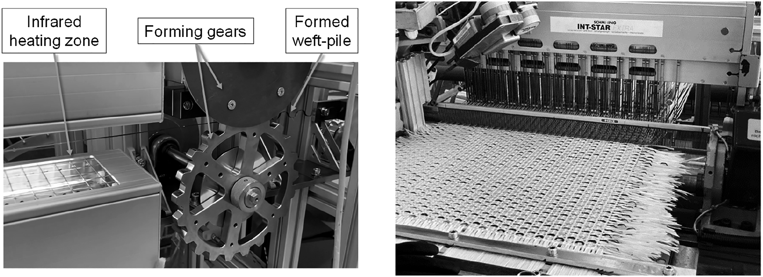
Specifications of the manufactured samples.

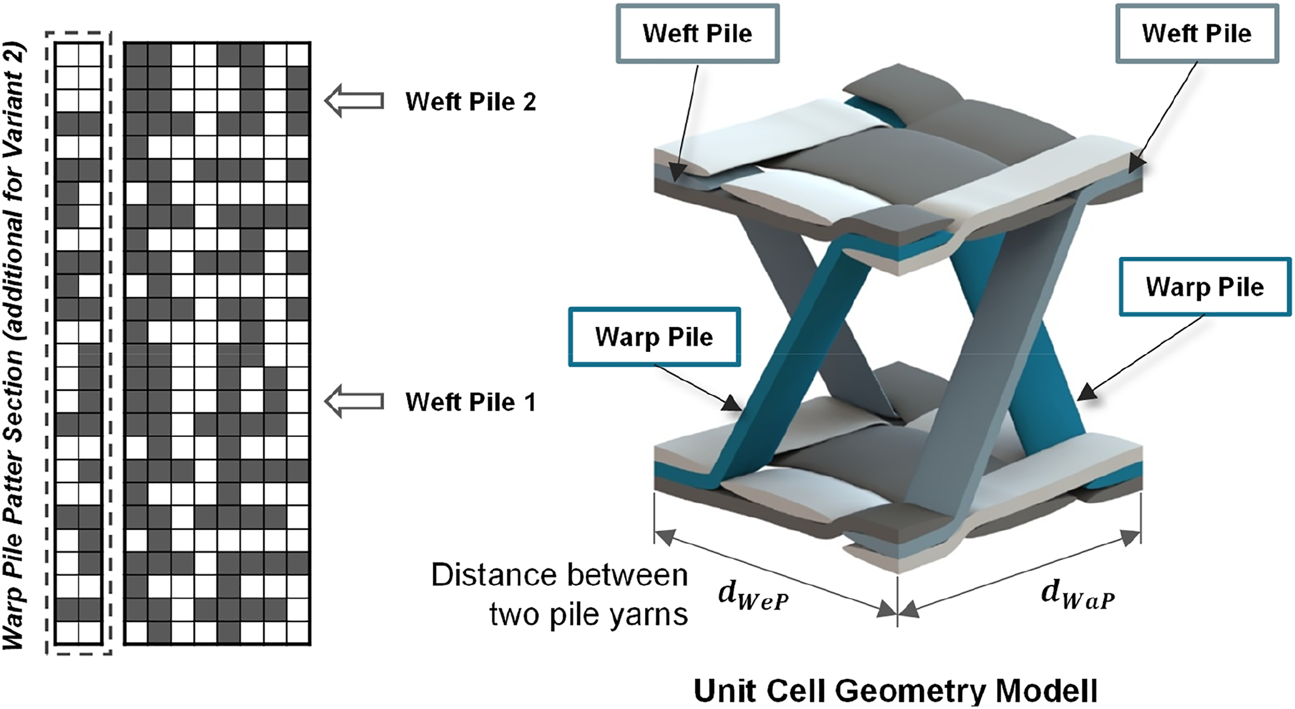
Pattern plot and basic design approach for the new developed truss-like woven fabrics.
With knowledge of the distances between the registered weft pile yarns and warp pile yarns, the new spacer fabrics can be described in more detail with the following relationships:

The TWFs were consolidated by lamination with a thermosetting matrix. The resin used (HEXION RIMR 135, see Table 2) has a sufficiently low viscosity for this and is absorbed into the fabric structure of the cover surfaces via capillary effects. For this purpose, a measured amount of resin was applied to a prepared plate tool and then the fabric was placed on it. After 24 h, the fabric was withdrawn and the procedure was repeated with the other side of the fabric. Finally, the consolidated specimen panels were post-cured (15 h at 80°C) according to the supplier’s instructions. The required specimens were cut from the panels for the respective tests. A consolidated panel and the cross-section of the new TWF in weft and warp direction are shown in Figure 3. Consolidated truss spacer fabric. (a) Cross section along weft direction. (b) Cross section along warp direction.
Experiments and results
Overview of the used test procedures.

Tensile-shear test
Tensile-shear test––preliminary considerations
According to standards, the shear properties of sandwich composites are determined on the basis of DIN 532943 33 or ASTM C273. 34 The load is applied using conventionally bonded metal plates, which are arranged rotatably or cardanically within the testing machine. The axis of rotation is within the specimen symmetry plane and perpendicular to the test direction. This allows the testing fixture to follow the shear-induced distortion of the specimen, eliminating external out-of-plane pressure or tensile stresses acting on the specimens. A disadvantage, however, is that the maximum test load is limited by the strength of the adhesive connection between the metal plates of the fixture and the specimen faces, which has so far been sufficient for testing honeycomb or foam sandwich composites, since these are also bonded together.
Overview of the stages during the tensile-shear test.

Tensile-shear test––results
The tensile-shear test was applied to all specimen series at a test speed of 6 mm/min (ca. 9% strain per minute). Both the fabric-based lightweight panels and the reference structures (honeycomb core) have orthotropically pronounced material behavior. They were therefore examined in the longitudinal direction (warp direction) and at right angles to this in the transverse direction (weft direction). The specimen preparation was the same for all series, with specimen material being removed in the required clamping area (see Figure 4). Tensile-shear test sample geometry.
The results of the tensile-shear test show clear differences (Figure 5). In the case of variant V1, no pronounced maximum force can be detected at the beginning of the test. The displacements of the cover surfaces are absorbed by shear distortion within the weft pile yarns inside the specimen and the force level persists up to approx. 3 mm displacement. As the test progresses, shear flow occurs within the specimen and as the displacement increases, the force increases again. At approx. 10 mm, a force maximum occurs. Tensile-shear behavior variant 1 (solid sine: warp direction, dashed line: weft direction).
In the weft direction, a significantly stronger increase in force is observed at the beginning of the test, which can be attributed to a higher structural stiffness due to the weft pile yarns aligned in the test direction. Here, too, there is a persistence of the force level, or a slight drop, with the force increasing again from 2 mm and remaining at a level from 6 to 10 mm of displacement. Despite the clear differences in the progress, ductile deformation behavior can be observed for the shear behavior of variant V1 over large displacements. This is also evident from the specimens during the test (Figure 6), which did not exhibit any abrupt failure behavior. Variant V1. Sample behavior during tensile-shear test.
A fundamentally different mechanical behavior can be observed for variant V2. In contrast to variant V1, this variant has additional warp pile yarns which, under shear load in the warp direction, enable both significantly higher stiffness and higher strength of the specimen. The warp pile yarns are optimally subjected to tensile or compressive stress, allowing high loads to be applied. Thus, tested in warp direction the behaviour of the panels under load in the first load phase during the test (up to approx. 2.5 mm displacement) corresponds to brittle material behaviour, which is why there is a substantial drop in the force within the specimen after the maximum force (Figure 7). However, as the test progresses, the force increases again from 6 mm displacement, since the remaining weft pile yarns are subjected to tensile loading similar to the core reinforcement of variant V1 (see Figure 8). In the weft direction, a similar effect of warp pile reinforcement can be observed. Compared to variant V2, the stiffness at the beginning of the test is significantly higher and a high force level is still achieved, which is maintained up to approx. 10 mm displacement. The load-bearing behavior of the warp and weft pile reinforcement in the panel core then merges. Shear behavior variant V2 (solid line: warp direction, dashed line: weft direction). Variant V2. Sample behavior during tensile-shear test.

The shear behavior of the reference variant is similar to variant V2. The applied forces increase to a maximum at approx. 1.5 mm displacement (Figure 9). The force then drops to a residual level that gradually decreases from 4 mm displacement. This characteristic can be visually reproduced on the specimens. Initially, delamination occurs between the core and the cover layers, followed by successive shear failure in the honeycomb core. Shear behavior of the reference panel (solid line: warp direction, dashed line: weft direction).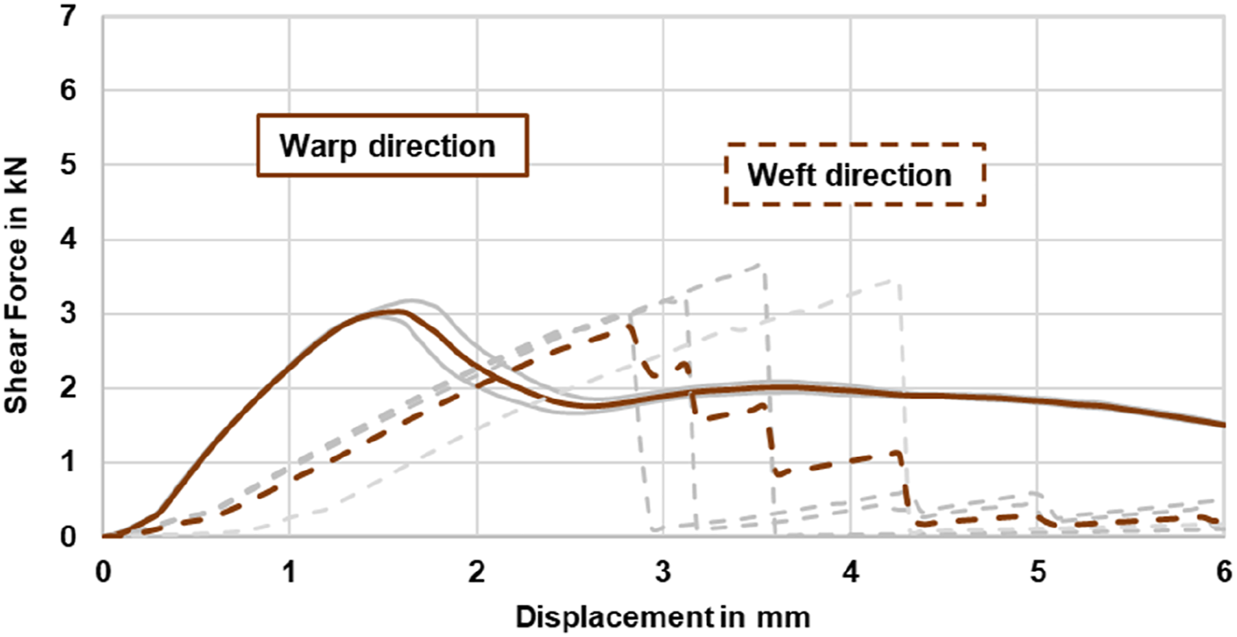
The increase in force in weft direction is significantly flatter, with different force maxima being achieved depending on the individual specimen, above which the reference specimens fail under delamination effects (Figure 10). In contrast to all other shear tests (V1, V2, reference warp), no residual load-bearing capacity remains. Reference. Sample behavior during tensile-shear test.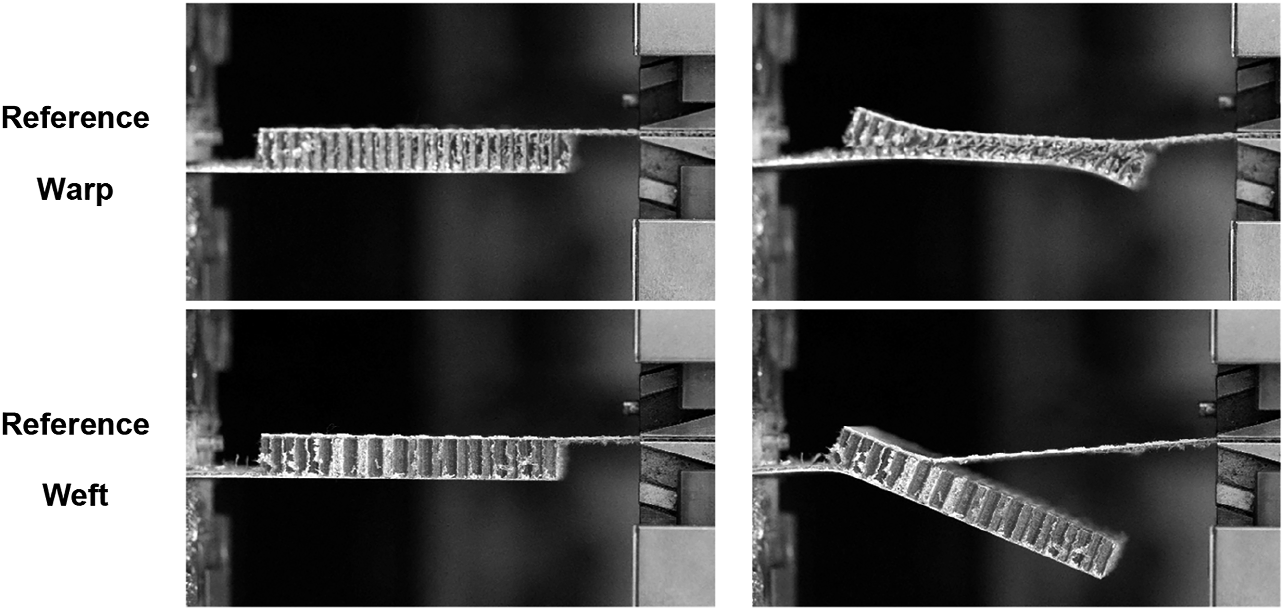
As a result of the shear test (Figure 11), it can be seen that the TWF-based lightweight panels tolerate higher shear deformations and are thus subject to a more ductile material behavior. This is not surprising inasmuch as the core of the fabrics consists of a deformation-tolerant fiber-matrix combination (glass-polyamide). The fabric-based variants benefit from the fact that the pile yarns in the panel interior are positively integrated into the cover layers, which means that a high residual load-bearing behavior is maintained despite increasing shear distortion and delamination of the panel specimens can be completely prevented. Furthermore, the additional warp pile reinforcement in variant V2 means that it can carry the highest overall tensile-shear loads in the warp and weft directions. It can be seen that the rather brittle material behavior of the warp pile yarns made of glass fibers and epoxy resin can be partially transferred to the entire panel. In contrast, the material behavior of the reference is characterized by delamination effects between core and cover layers, which could be observed in particular in the weft direction. At the same time, the tolerable shear distortions are significantly lower. Overview of the shear behavior (V1 - variant 1, V2 - variant 2, R - reference).
Compression test
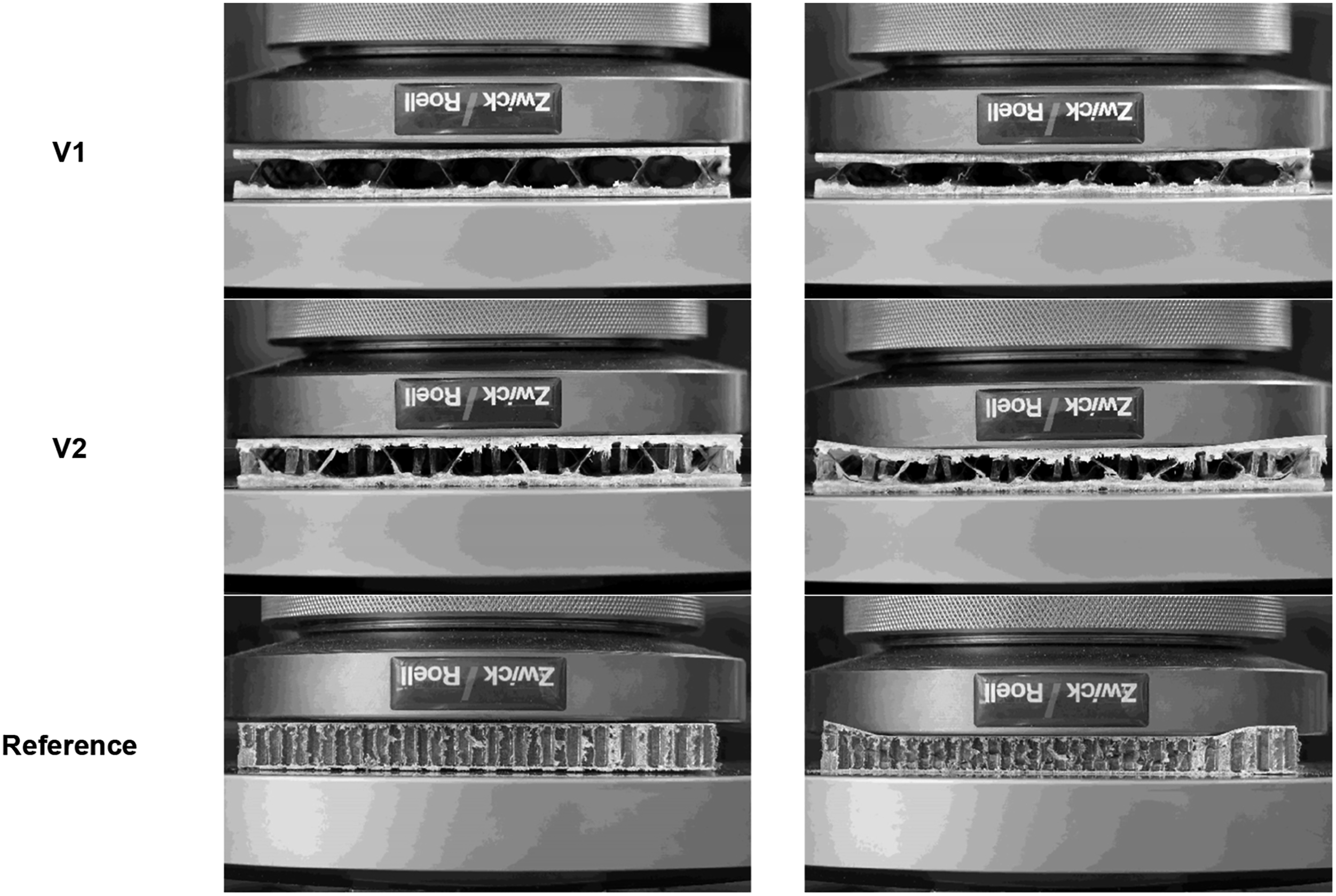
The compression test was carried out for all variants using square specimens with dimensions 108 × 108 mm2 (length x width, parallel to warp and weft direction). The compression tests were carried out at a constant test speed of 1 mm/min (ca. 10% per minute) up to a displacement distance of 1.2 mm. The results obtained are shown in Figure 12. During the compression tests, significant differences in the compression behavior of the truss spacer fabric based variants compared to the reference can be observed. The highest compressive stiffness and stability were found in the reference specimens. The honeycomb core of the reference remained intact until the maximum force (up to 35 kN) was reached, but then collapsed with bulging of the cell walls Figure 13, which was accompanied by a decreasing compressive force on the specimen as the test progressed. Of the TWF based panels, Variant V2 achieved the highest compressive stability, reaching forces of 22.5 kN. In this case, the panel core showed increasingly critical deformation effects of the pile filament reinforcement inside, while maintaining a consistently high residual load-carrying capacity, as is characteristic of a gradual failure behavior. It can be observed that the pile yarns in the panel interior bulge laterally during the test. In terms of structural mechanics, this means that compressive loads in the panel have to be absorbed by the pile threads in the form of bending loads, which is why the compressive stiffness subsequently remains below that of the reference. In comparison, variant V1 again showed significantly lower compressive stability and achieved a maximum force of only 6 kN. The pure weft pole reinforcement of glass filament/polyamide tapes reacts under pressure with pronounced buckling effects. Nevertheless, it can be said that the truss spacer fabric-based variant V2 still achieves good compressive stability compared with the reference. Overview of the compression properties. Sample behavior under compression load. Left: sample at test beginning, right: at test end.
Bending test
The bending test was carried out using the 4-point method with a uniform specimen geometry of 117 mm length at a width of 55 mm. Analogous to the tension-shear test, the specimen was taken from consolidated panels in warp and weft direction. The support distance was 80 mm and the width of the compression fin was 22 mm. The test was carried out at a test speed of 2 mm/min.
During the test, Variant V1 shows ductile deformation behavior (Figure 14), with no clearly pronounced maximum force being reached during the course of the tests (Figure 15). The bending deformation is initiated over the entire specimen length and in both cover surfaces by the weft pole reinforcement. In the warp direction, however, a bending displacement (relative to the compression fin) of 1.6 mm results in a bending force of approx. 400–600 N, and in the weft direction, from approx. 4 mm displacement, a bending force of approx. 600 N is reached. In both directions, the force remains relatively constant over the displacement. Bending properties of truss spacer fabric reinforced panel Variant V1. Sample behavior of truss spacer fabric reinforced panel variant V1 under bending load.

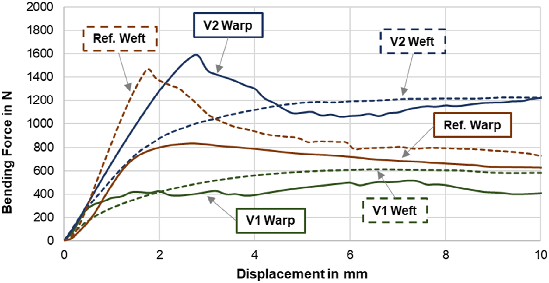
In comparison, clear differences can be seen in the bending behavior of Variant V2 (Figure 16). The additional reinforcement with warp pile yarns causes a stiffening of the specimen, which is evident from the stronger increase in force, as well as a significantly increased force level (Figure 17). In particular, in the warp direction, there is a pronounced force maximum of approx. 1,600 N (at approx. 2.3 mm, with the bending force remaining at a constant level of approx. 1,000–1,200 N thereafter. The bending behavior in the weft direction can be characterized as ductile, analogous to variant V1. No specific maximum occurs; rather, the specimens are loaded at a force level of approx. 1,200 N from approx. 4 mm. Bending properties of truss spacer fabric reinforced panel variant V2. Bending properties of reference panel.

In comparison with the TWF variants, the bending behavior of the reference with honeycomb core is comparable to that of variant 2, with the weft direction of the reference being similar to the warp direction of V2 and vice versa (Figure 18). The stiffness of the reference in the weft direction is still slightly higher than that of variant V2 and the maximum force is already reached at 1.8 mm (see Figure 19). In comparison, the stiffness in the warp direction of the reference is lower than in the weft direction of V2, with a constant bending force acting from approx. 2 mm, but slowly decreasing from 4 mm deformation. Depending on the specimen, the residual force level in the weft direction varies, but is on average lower than that of variant V2. In contrast to the V1 and V2 variants, it can be observed in the reference that the honeycomb core collapses locally in the area of the force application in the course of the test, which is accompanied by cracking and delamination of the cover surfaces (Figure 20). Sample behavior of truss spacer fabric reinforced panel variant V2 under bending load. Sample behavior of the reference panel under bending load. Bending behavior in comparison.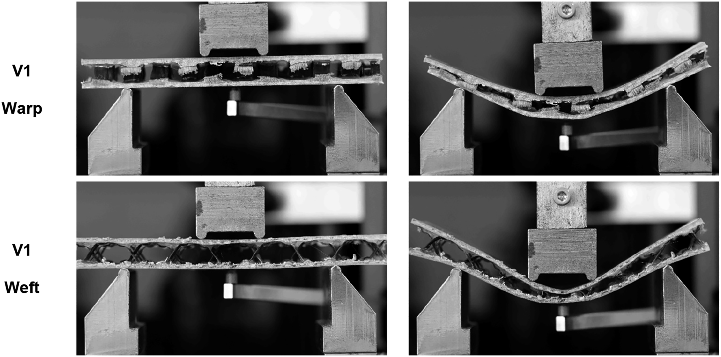

Discussion
Experimental results in comparison.

*referred to the tested specimen area; **given by kN/kg for forces and kN/(mm × kg).
As a result of the tests, the high structural mechanical level of the reference can be confirmed in the first instance. In particular, high compressive loads of over 35 kN were determined under compressive loading. The reason for this is the mechanically advantageous geometric arrangement of the cell walls within the honeycombs. This is also partly reflected in the bending behavior, in which the compressive strength of the honeycomb core takes over the load distribution between the cover surfaces. However, local load peaks, such as in the area of force application, are not transferred to the surrounding panel structure due to the high core stiffness. Instead, the cells of the honeycomb core collapse locally, causing the cover surfaces in that area to also overload and break. Another disadvantage of the reference panels is the lack of strength of the purely adhesive-based coupling between the core and cover surfaces. In the newly applied tensile-shear test, this aspect becomes clear. Combined load conditions of shear and bending lead to peeling stress between the panel layers, causing the faces to delaminate from the honeycomb core. Particularly in the tensile-shear test, a completely different structural behavior can be made visible with the new TWFs. The panel core formed from the pile yarns is interlaced with the cover surfaces by means of reinforcing fibers. This allows a significantly improved transfer of shear loads in the form of tensile loads into the pile yarns. Delamination effects as with the reference are completely prevented. The bending tests also show that, thanks to the lower compressive strength and stiffness of the pile yarns compared with the reference, local load peaks are avoided and bending loads are introduced completely into the structure. Failure effects typical of the reference, e.g. in the area of force application, no longer occur, but are diverted and distributed via the resilience of the pile yarns. Based on the test results, it can be seen that TWF panels have a constant residual load-bearing capacity, while the stability of honeycomb core panels decreases with increasing deflection. It is also clear that a hybrid material composition in the form of thermoset and thermoplastic consolidated pile yarns has a positive influence on the load-bearing characteristics. Thus, the thermoset consolidated pile yarns allow high peak loads with high structural stiffness, while the thermoplastic pile yarns ensure residual load-bearing capacity after failure of the warp pile yarns due to their ductile material behavior. In terms of compressive stability, panels made of TWF can still achieve comparable compressive stability, although they do not quite reach the high load-bearing capacity of the reference. Particularly stable are panels with warp and weft pile reinforcement (variant V2).
Overall, the new TWFs represent a promising solution for the structural development of future panels and panel-like lightweight structures. In addition to their mechanical performance, initial tests on the drape of the TWF have shown that they have forming behavior similar to that of textiles. Curvature-related residual stresses are effectively relieved by isolated sliding of the reinforcing filaments in the cover surfaces and in the core, which allows improved draping and forming (Figure 21). The structure of the TWF is regularly open, so that inserts can be integrated within the raster of the fabric structure to reinforce the structure, and this already during the fabrication and forming of the fabric structure. The point was included within the Conclusion section for further leading work. However, a search in related research topics also shows that the integration of additional reinforcing elements is so far only in use for honeycomb. The structural variants that can be implemented by the TWF, on the other hand, offer new starting points that are completely unknown on the part of commercial honeycomb or foam core based structures. Draped and consolidated TWF-panel.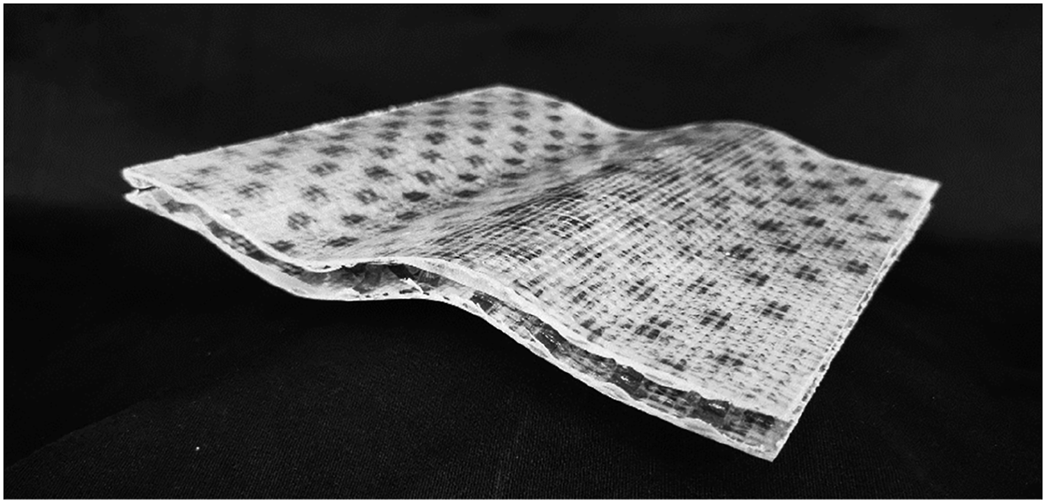
Conclusion
In this article, FRP sandwich-like panel structures made of newly developed truss-like woven fabrics (TWF) are presented, which have pile yarn reinforcement running spatially in both warp and weft directions in their interior. They are ideally suited for the production of lightweight structures and, compared to conventional sandwich constructions, have a significantly increased delamination resistance and deformation tolerance due to the continuous, form-fit reinforcement fiber structure. This aspect is illustrated in this article by means of a modified tensile-shear test. In the first instance, this test allows the evaluation of mechanical properties in comparison with conventional honeycomb sandwich panels. As the test progresses, peel stresses are also introduced into the edge regions of the specimens, which in conventional sandwich structures lead to catastrophic failure with delamination of the face sheets from the panel core. In contrast, the investigated panel specimens made of TWF do not exhibit delamination and showed ductile material behavior. In terms of bending characteristics, honeycomb sandwich and TWF based panels (variant V2) show comparable bending properties. However, the consolidated pile threads in the core of the TWF panels allow improved load transfer, so that the specimens are subjected to bending uniformly along their length, while the honeycomb sandwich panels fail locally due to collapse of individual honeycombs and delamination of the face sheets. In the compression test, however, the well-known high performance and compression resistance of the honeycomb cores could be reproduced by the reference samples. The TWF panels of variant V2 also achieve good compressive strength. Here it can be assumed that a higher pile density and, if necessary, the use of other reinforcing fiber materials such as carbon fibers will enable significantly higher compressive strength in the future.
Overall, it was shown that the use of TWF panels provides a promising new material basis for the production of lightweight panels. Particularly regarding critical shear stresses but also high bending loads, they exhibit excellent deformation tolerance, while delamination of the layers is completely avoided compared with the state of the art. The deformation tolerance also reflects a high achievable deformation work and thus a high suitability for energy absorption in crash applications, as already demonstrated in the research work of Vo 38 using related fabric structures. Conventional fiber and matrix materials can be used to manufacture the TWFs, or compatible substitute materials from renewable and sustainable sources in the future. The weaving production of the TWF is based on commercially available machine technology and offers a high degree of automation and reducibility in panel fabrication. In addition, the regularly open structure of the TWF enables the integration of inserts for load transfer into the panel, as well as back-ventilation and drainage of lightweight structures under rapidly and frequently changing climatic conditions, such as in aerospace or comparable. Future research on TWF panels aims at increasing mechanical properties and functionalization, e.g., using additional core materials, textile-integrated sensor technology and compatibility with conventional panel construction methods and assembly of component peripherals.
Footnotes
Acknowledgements
The IGF project 20245 BR of the Forschungsvereinigung Forschungskuratorium Textil e.V., Reinhardtstr. 12-14, 10117 Berlin was funded by the Federal Ministry for Economic Affairs and Climate Action through the AiF within the program for the sponsorship of Joint Industrial Research (IGF) based on an enactment of the German Parliament.
Declaration of conflicting interests
The author(s) declared no potential conflicts of interest with respect to the research, authorship, and/or publication of this article.
Funding
The author(s) disclosed receipt of the following financial support for the research, authorship, and/or publication of this article: This work was supported by the Allianz Industrie Forschung (IGF 20245 BR).