
Abstract
The combination of appropriate materials and structural design can compensate for flaw of a single pattern, providing the products with better functionalities. In this study, the custom-made nonwoven fabric machine can unwrap the filament tows before needle punching stage. Sandwich composites are proposed, consisting of two nonwoven fabrics as surface layers and laminated loops of filaments as the core. The puncture resistance of the sandwich composites are examined in terms of weight of filament loops and needle-punching depth, examining their influences. The employment of filaments has a remarkable influence on the mechanical performance of the composites. GF4G has static puncture resistance, dynamic puncture resistance, and bursting strength that are 89%, 30%, 88% higher than those of GF1G; 332%, 127%, and 500% higher than those of 2G; and 671%, 400%, and 1260% higher than those of G. Using filaments to reinforce nonwoven fabrics only requires simple equipment and easy operation. Furthermore, based on the requirements of different final products, diverse filaments and multiple parameters can be combined, thereby providing the composites with efficient production, solid reinforcement, and broad applications.
Keywords
Introduction
Nonwoven geotextiles are featured by having ease of process, low production cost, efficiently high yields, and good flexibility and water permeability [1], and are thus commonly used in water conservancy, dams, roads, airport, and soil and water conversation. Moreover, geotextiles are also an important construction material in the fields of low-impact development and sponge city. Regardless of whether they are used for reinforcement, separation, drainage, filtration, or protection, geotextiles can be locally damaged when being exerted a force that is caused by sharp objects, such as rocks, roots and branches of trees, and aggregates that are used with cements. As a result, the puncture resistance is a critical feature of geotextiles.
At times, a single material of geotextiles do not satisfy the functionalities required in construction. An ideal design involves composites which are composed of two or multiple fibers, compensating for the drawback of mono-type material as well as creating better functionalities [2–4]. In addition, variations in structure reciprocate to mechanically strengthen the materials, and one common example is a sandwich structure [5–7]. Sandwich composites consist of two surface layers and one core, and are able to provide high mechanical properties and a low weight. For example, Li et al. developed electromagnetic interference shielding sandwich composites that were made of carbon fabrics and nonwoven fabrics using needle punching and thermal bonding, and examined the static and dynamic puncture resistances [8]. Li et al. used Kevlar fabrics, glass fabrics, and recycled Kevlar/Nylon/low-Tm polyester nonwovens. The materials were processed with needle punching and thermal bonding in order to form compound fabrics, whose static and dynamic puncture resistances were then evaluated [9]. Yan et al. conducted two studies on sandwich composites containing glass fabrics and the composites were evaluated for their mechanical properties [10,11]. Based on the study by Valença et al., composites that were composed of Kevlar fabrics and glass–fiber fabrics had higher mechanical strength, bending property, and impact energy [4]. However, use of glass–fiber fabrics, Kevalar fabrics, or carbon–fiber fabrics causes higher production cost.
In order to obtain high mechanical strength geotextiles in an efficient and economical manner, this study uses a custom-made nonwoven fabric machine as seen in Figure 1. The filament tows can be separated into single filaments using two pairs of friction rollers, after which the third pair of rollers laminate the filaments into loops over a nonwoven layer that is mounted on a conveyer belt. Another nonwoven layer is laminated over the filament loops, and then needle punched into bonded sandwich composites. In our pilot study, the scattered single fibers are proven to strengthen the cohesion between the staple fibers and the nonwoven fabrics for homogeneity. The filaments are laminated in loops in order to obtain a non-directional reinforcement that highly improves the mechanical properties of the composite geotextiles. Manufacturing parameters used in nonwoven process have influence on mechanical properties and puncture resistance of nonwoven products [12–14]. The speed of conveyer belt is changed in order to manipulate the weight of filament loops. This study investigates the effects of parameters (i.e. weight of filament loops and needle-punching depth) on the puncture resistance of the composites. Techniques of filament-reinforced nonwoven fabrics can be used in fields of geotextiles and other composites. Filament-reinforcement provides built-up diversity. Namely, combinations of various amounts and types of filaments provide the final products with suitable functionalities and substantial quality, which promises a perspective to the related developments.
Illustration of the reinforcing method uses friction to unwind filament tow: (1) filament tow, (2) friction roller, (3) lamination roller, (4) nonwoven fabric, (5) conveyer belt, (6) needle punching device, and (7, 8) guide plates.
Experimental
Materials
Kevlar uni-directional selvages (Dupont, US) include K29, K49, and K129 multi-filaments. The recycled Kevlar fibers have a fineness of 1.5–2 Denier (D) and a length of between 50 and 60 mm. The three-dimensional crimped polyester (PET) fibers (Far Eastern New Century, Taiwan) have a fineness of 7D and a length of 64 mm. Low-melting-point PET (LMPET) fibers (Far Eastern New Century, Taiwan) have a fineness of 4D and a length of 51 mm. LMPET fibers have a sheath-core structure. The glass transition temperature of the sheath is 60℃, while its melting point is 110℃. PET filament (Universal Textile, Taiwan) has a fineness of 500D and a single fiber strength of.3 gf/den.
Preparation of sample
The proposed composites are made of a sandwich structure. The surface layers use the optimal recycled Kevlar/PET/LMPET nonwoven fabrics that are obtained from the previous studies [15–17]. They have a mass per unit area of 200 ± 20 g/m2 and are composed of 20 wt% recycled Kevlar staple fibers, 60 wt% PET staple fibers, and 20 wt% LMPET staple fibers. The core is PET filaments. The manufacture starts with a nonwoven layer being mounted on a conveyer belt. Then the friction rollers unwind the filament tows, after which the separate filaments are laminated in loops over the nonwoven layer using the third pair of roller, seen as Figure 2((a) to (d)). Finally, another nonwoven layers is used to cover the loops of filaments, and the laminated sandwich is needle punched and then hot pressed at 120℃. The filament cores have weights of 410, 460, 550, and 640 g/m2, while the needle-punching depths are 15, 17, and 19 mm. This study is conducted following the limits of the needle-punch depth of needle punching machine, and the maximum one is 19 mm. When the belt is at a high speed, it carries smaller weight of filament loops, and vice versa. In this study, the weight of filament loops is adjusted by the speed of the belt as well as the limit of the needle punching machine. Table 1 shows the denotation of samples, including single layer nonwoven fabric (G), two-layered nonwoven fabrics (2G), and sandwich composites (GF1G, GF2G, GF3G, and GF4G) where the initial and ending letter “G” refers to nonwoven fabrics, and “F1, F2, F3, and F4” refer to filaments at four different weights. “G” and “2G” serve as the control group.
Stereomicroscopic images of (a) filament tows, (b) separate filaments, (c) lamination of filaments, and (d) the loops formed of filaments. Denotations of samples.

Tests
Static puncture resistance
The static puncture resistance (N) of samples is measured using an Instron 5566 universal tester (Instron, US) at a constant rate of 508 mm/min in accordance with ASTM F1342-05. The 100 mm×100 mm samples are placed between two circular plates with 10-mm diameter holes in the center. The pointed probe has a diameter of 5 mm as seen in Figure 3(a). A total of 10 samples are used for the test.
The probes used for (a) static puncture resistance, (b) dynamic puncture resistance, and (c) bursting strength tests.
Dynamic puncture resistance
According to NIJ Standard 0115.00, the dynamic puncture resistance (N) of samples is measured using a drop-tower machine (Guang Neng Machinery Co., Ltd, Taiwan) that is equipped with PCD300A data acquisition (Sanlien Corp., Taiwan). With a 0.07 mm shaft radius and 24° conical angle as in Figure 3(b), the probe has a load of 2.8 kg, and was dropped from 284 mm height for resisting against 24 J energy. Samples measuring 100 mm × 100 mm are clamped between two square plates with a 40-mm diameter hole in the center. A total of 10 samples are used for the test.
Bursting strength
Based on ASTM F2054-07, the bursting strength (N) of the samples is measured using Instron 5566 universal tester (Instron, USA) that is attached with 10 kN load cell. The cross-head speed is 100 mm/min. Specimens have a size of 150 mm × 150 mm and are mounted between two plates with 45-mm diameter hole. The cylindrical probe has a diameter of 25 mm and a spherical tip (Figure 3(c)). A total of 10 samples are used for the test.
Statistical analyses
This study uses one-way analysis of variance (ANOVA) of SPSS statistics software (version 20.0). One-way ANOVA is the statistical procedure to compare three groups or more, in terms of variation in the means. The alpha (α) level is commonly set as 5% with a confidence interval of 95%. p < 0.05 indicates significant difference in the variables between groups. Specific analyses of variations between groups are presented with significant differences that are examined using one-way ANOVA. The post hoc Scheffe's test is finally used to analyze the significant difference in specified parameters.
Results and discussion
Effects of weight of filament loops on static puncture resistance of sandwich composites
Figure 4 shows the static puncture resistance of the experimental group (i.e. sandwich composites, including GF1G, GF2G, GF3G, and GF4G) and the control group (i.e. G, 2G) as related to the weight of filament loops. GF1G, GF2G, GF3G, and GF4G that are made with a needle-punching depth of 19 mm have static puncture resistance of 172, 177, 195, and 325 N. The static puncture resistance of GF4G is 89%, 332%, and 671% higher than that of GF1G, 2G, and G. The results of one-way ANOVA show that based on different structures, the significant differences for static puncture resistance is (F = 138.97, p < 0.00). The post hoc Scheffe's test shows that the static puncture resistance from highest to lowest can be ranked as GF4G>GF3G, GF2G, GF1G>2G>G, indicating three facts: (1) the static puncture resistance of GF4G is significantly higher than that of GF3G, GF2G, GF1G, 2G, and G; (2) there is no significant difference in the static puncture resistance among GF1G, GF2G, and GF3G, but the experimental group is significantly greater than the control group; and (3) the static puncture resistance of 2G is significantly higher than that of G. In short, sandwich composites exhibit extraordinary static puncture resistance when they are composed of 640 g/m2 of filaments. In addition, the work of GF4G is also remarkably higher than that of other samples. In this study, the speed of the convey belt is changed to adjust the content of filaments of 410, 460, 550, and 640 g/m2. The weight of filament loops of GF4G is 90 g/m2, 200 g/m2, and 250 g/m2 greater than that of GF3G, GF2G, and GF1G. The variation in the weight of filament loops is only 50–90 g/m2. Figure 5 also shows that increasing the filaments has a positive influence on the mass per unit area and thickness. In addition, apparent opening size is conducted using the smallest glass beads (#200/0.08 mm) as specified in ASTM D4751. All of GF1G, GF2G, GF3G, and GF4G have a sieving rate below 5% and the pore size is determined to be 0.08 mm. Based on ASTM D737-04, the air permeability test is performed to compare the density of the composites. With a specified needle-punching depth of 19 mm, G, 2G, GF1G, GF2G, GF3G, and GF4G have air permeability of 116, 63, 26, 27, 20, 13 cm3/cm2/s. In particular, GF4G has the lowest density and thus a significantly greater static puncture resistance. Because the stress is imposed in a small cross-sectional area, the more filaments per unit area, the greater the thickness, and the higher the static puncture resistance.
Static puncture resistance and work of samples as related to needle-punching depths of 15, 17, and 19 mm. (a) mass per unit area and (b) thickness of samples as related to needle-punching depths of 15, 17, and 19 mm.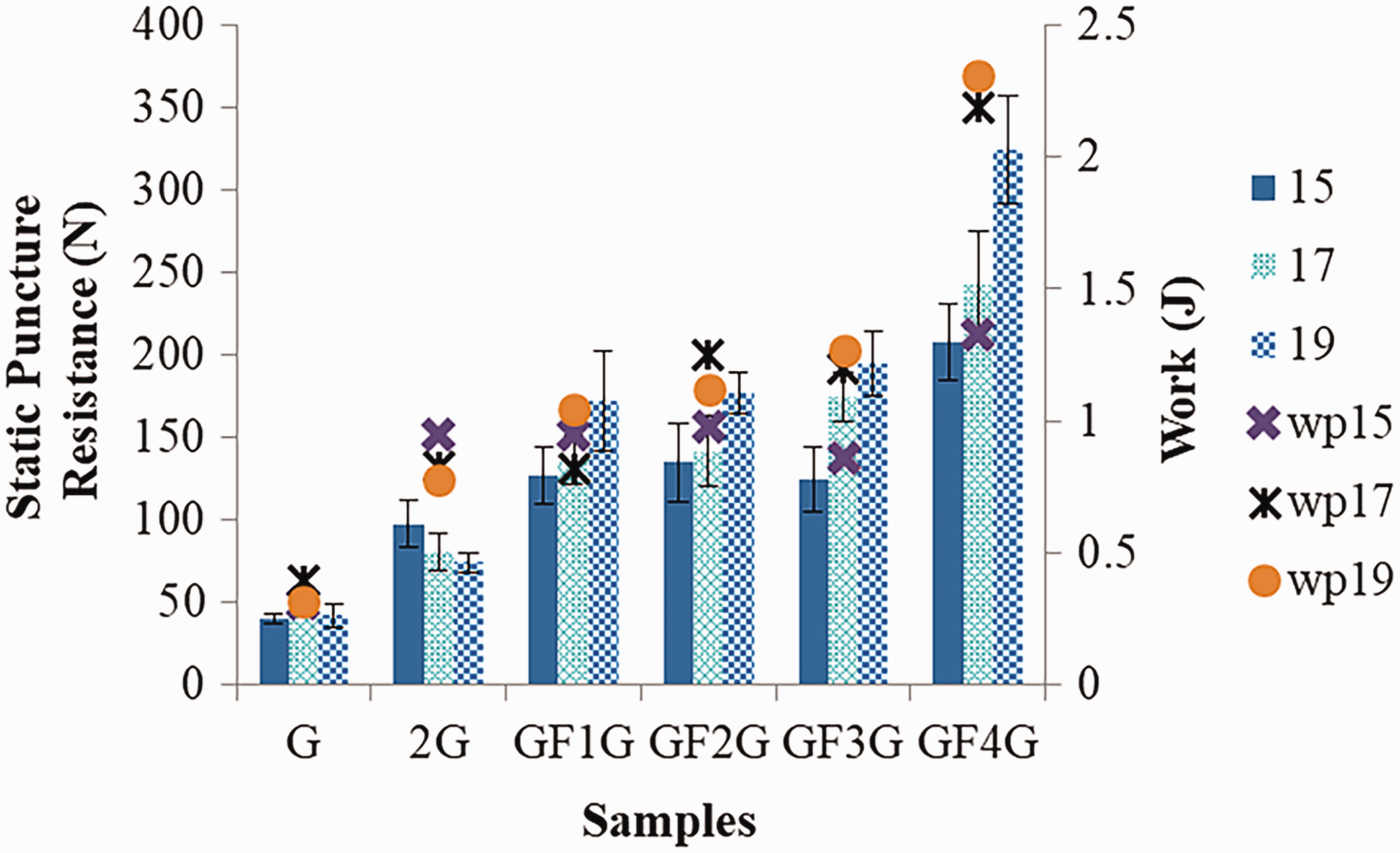

Effect of needle-punching depth on static puncture resistance of sandwich composites
Figure 4 shows the static puncture resistance of sandwich composites as related to needle-punching depth. A needle-punching depth of 15, 17, and 19 mm provides GF4G with static puncture resistance of 208, 242, and 325 N. P19 contributes a 56% higher static puncture resistance than P15. The results of one-way ANOVA show that based on needle-punching depths, the significant differences for static puncture resistance is (F = 23.57, p < 0.00). The post hoc Scheffe's test shows that the static puncture resistance of sandwich composite from highest to lowest based on the corresponding needle-punching depth can be ranked as P19>P15, P17. A needle-punching depth of 19 mm (P19) causes significantly higher static puncture resistance than a needle-punching depths of 15 mm (P15) and 17 mm (P17). P19 contributes to a greater density of the sandwich structure, and thus a higher static puncture resistance. Moreover, Figure 4 also shows that the higher the needle-punching depth, the higher the work. Figure 6 shows the strength–displacement curves of GF4F sandwich composites, which are needle punched at a depth of 19 mm, and the deformation is relatively smaller. This result suggests a greater compactness featured by the sandwich composites, which in turn generates a greater friction force against the probe.
The strength–displacement curves of GF4G as related to needle-punching depths of 15, 17, and 19 mm.
Effects of weight of filament loops on dynamic puncture resistance of sandwich composites
Figure 7 shows the dynamic puncture resistance of the experimental group and control group as related to the weight of filament loops. With a specified needle-punching depth of 19 mm, GF1G, GF2G, GF3G, and GF4G have dynamic puncture resistance of 96, 105, 113, and 125 N. The dynamic puncture resistance of GF4G is 30%, 127%, and 400% greater than that of GF1G, 2G, and G. The results of one-way ANOVA show that based on different structures, the significant differences for dynamic puncture resistance is (F = 72.60, p < 0.00). The post hoc Scheffe's test shows that the dynamic puncture resistance of sandwich composite from highest to lowest can be ranked as GF4G>GF1G>2G>G, indicating three factors: (1) GF4G has a significantly higher dynamic puncture resistance than GF1G, 2G, and G; (2) GF1G has a significantly higher dynamic puncture resistance than 2G and G; and (3) 2G has a significantly higher dynamic puncture resistance than G. The results suggest that GF4G that contains 640 g/m2 of filaments have the maximum dynamic puncture resistance. Massively entangled filaments have a higher mass and thickness per unit area, which contributes to a higher dynamic puncture resistance. GF1G, GF2G, GF3G, and GF4G show different trends in terms of the dynamic and static puncture resistance. The static puncture resistance is performed using a constant rate until the probe penetrates the sample, while the dynamic puncture resistance is performed letting a pointed probe to plummet from a specified height and rupture the same instantly. Therefore, the dynamic puncture resistance of GF1G, GF2G, GF3G, and GF4G is lower than their static puncture resistance with large standard deviations and insignificant differences in the dynamic puncture strength among groups.
Dynamic puncture resistance of samples as related to weight of filament loops (410, 460, 550, and 640 g/m2) and needle-punching depth (15, 17, and 19 mm).
Effect of needle-punching depth on dynamic puncture resistance of sandwich composites
The dynamic puncture resistance of experimental group increases when the needle-punching depth increases. A needle-punching depth of 15, 17, and 19 mm provides GF4G with dynamic puncture resistance of 99, 109, and 125 N. P19 contributes a 26% higher dynamic puncture resistance than P15. The results of one-way ANOVA show that based on needle-punching depths, the significant differences for dynamic puncture resistance is (F = 7.03, p < 0.00). The post hoc Scheffe's test shows that regardless of whether the needle-punching depth is 15, 17, or 19 mm (i.e. P15, P17, P19), there is no significant difference in the static puncture resistance between GF1G and GF2G. This is due to the high dynamic impact force and low dynamic puncture resistance of samples. As a result, the standard deviation is high. The static puncture resistance of GF3G and GF4G based on the corresponding needle-punching depth can be ranked as P19>P15, indicating that a needle-punching depth of 19 mm causes to a greater dynamic puncture resistance than that of 15 mm. Therefore, using needle-punching depth of 19 mm creates a higher density and thus a better dynamic puncture resistance.
Effects of weight of filament loops on bursting strength of sandwich composites
Figure 8 shows the bursting strength and work of the experimental group and the control group both increases as a result of increasing weight of filament loops. With a specified needle-punching depth of 19 mm, GF1G, GF2G, GF3G, and GF4G have bursting strength of 2737, 3905, 4418, and 5142 N. The bursting strength of GF4G is 88%, 500%, and 1260% greater than that of GF1G, 2G, and G. The results of one-way ANOVA show that based on different structures, the significant differences for bursting strength is (F = 104.42, p < 0.00). The post hoc Scheffe's test shows that bursting strength from highest to lowest can be ranked as GF3G, GF4G>GF1G>2G>G; GF2G>2G>G, indicating three facts: (1) there is no significant difference in bursting strength between GF3G and GF4G; (2) the bursting strengths of GF3G and GF4G are significantly greater than that of GF1G, 2G, and G; (3) GF1G has a significantly greater bursting strength than 2G and G; (4) the bursting strength of 2G is significantly greater than that of G; (5) there is no significant difference in bursting strength between GF2G, GF1G, GF3G, and GF4G, but their bursting strength is significantly higher than that of 2G and G. In short, GF3G and GF4G have an optimal bursting strength. When sandwich composites are composed of more filaments, they have a greater thickness and can bear a higher load. In addition, filaments (i.e. the core) are formed in continuous loops, after which needle punching and hot pressing provide the sandwich composites with a structure that resembles a high-strength panel. As a result, the sandwich composites yield an improved bursting strength.
Bursting strength and work of sandwich composites as related to weight of filament loops and needle-punching depth.
Effect of needle-punching depth on bursting strength of sandwich composites
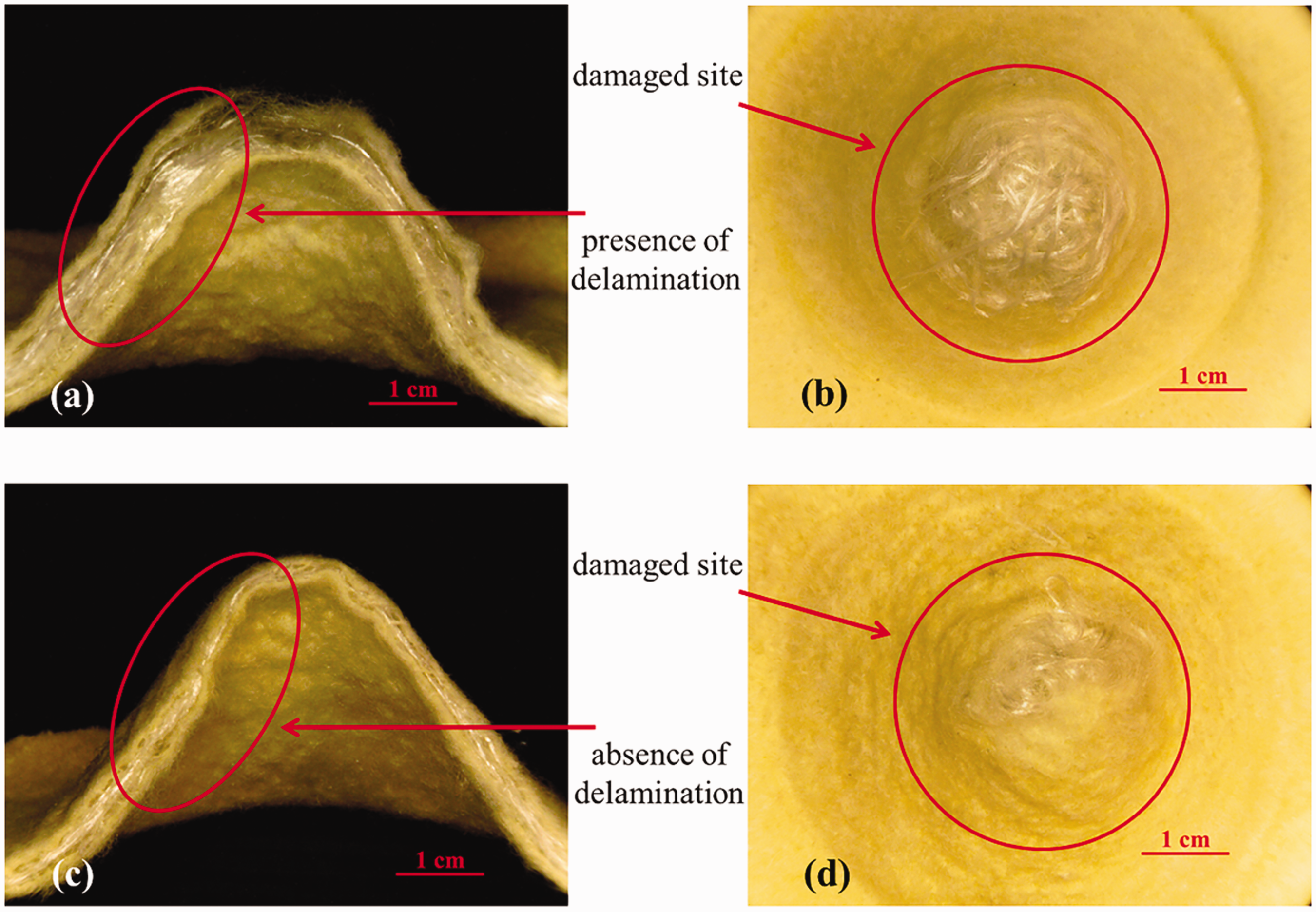
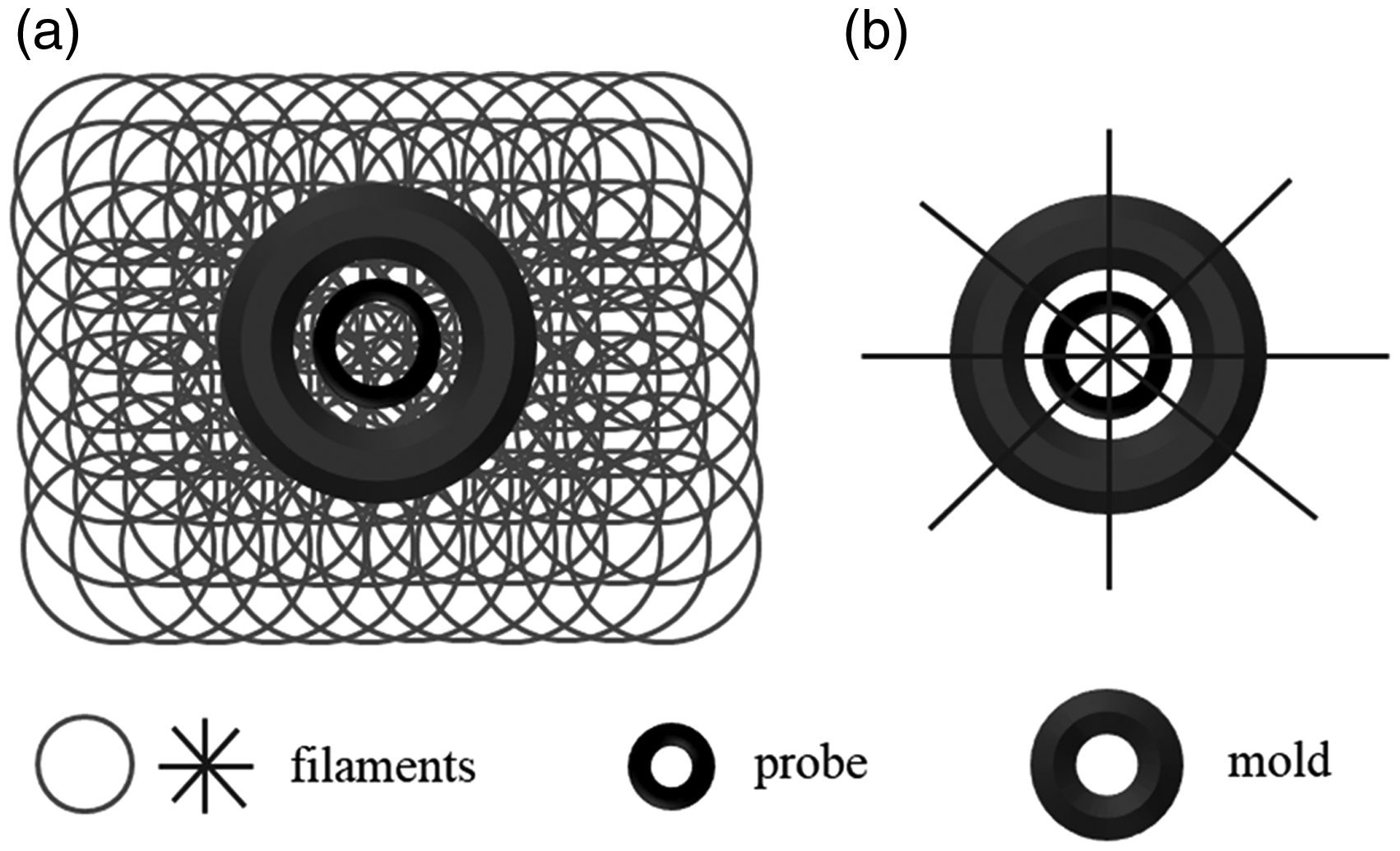
The statistical analyses show that there is no significant (F = 0.20, p < 0.82) difference in bursting strength among GF1G, GF2G, GF3G, and GF4G, suggesting that a needle-punching depth of 15, 17, or 19 mm (i.e. P15, P17, P19) does not have an influence and the experimental group has similar bursting strength. The probe of bursting strength has a spherical head and thus has a larger cross-sectional area to withstand an externally exerted stress. Moreover, the sandwich composites that are composed of continuously formed filament loops are firmly affixed between the clamps as shown in Figure 9. Therefore, even a needle-punching depth of 15 or 17 mm does not improve the overall compounding effect, but the clamps affix the sample firmly to form a compact structure, which makes needle-punching depth an irrelevant parameter to the bursting strength. Figure 10 shows images of GF4G after bursting strength test, where P15 leads to the presence of delamination after bursting damage. Moreover, regardless of whether it is P15 or P19, the damage site of GF4G is surrounded by entangled filaments. It is surmised based on Figure 11, GF4G is affixed and compressed by the test clamps. Therefore, the structure is secured and enhanced by the tester, which in turn eliminates the influence of needle-punching depth on the bursting strength of GF4G. Figure 12(a) is used to examine the relationship among filaments, the probe, and the mold, which can be simplified as seen in Figure 12(b). As a result, there is no significant difference in the bursting strength of GF4G that is made of needle-punching depth of 15, 17, and 19 mm because samples are composed of the same weight of filament loops, affixed by an identical force of clamps, and then damaged by an identical bursting force. Moreover, Figure 13 shows the strength–displacement curves are similar regardless of whether it is P15, P17, or P19. The probe first contacts then damages the sample, the process of which causes the deformation in GF4G with the similar trend. This result once again proves that samples are being affixed by the clamps and needle-punching depth does not influence the bursting strength.
The test assembly and illustrative diagram of bursting strength test. Images of GF4G after bursting strength test: (a) cross-section and (b) damaged site of GF4G made of a needle-punching depth of 15 mm; (c) cross-section and (b) damaged site of GF4G made of a needle-punching depth of 19 mm. The stereomicroscopic image of GF4G, showing the damaged site is surrounded by filaments. Illustrative diagrams of bursting strength test: (a) the relationship among filaments, probe, and mold, and (b) the simplified diagram. The strength–displacement curves of GF4G as related to the needle-punching depth of 15, 17, or 19 mm.


Conclusion
The purpose of this study is to investigate the reinforcing effect of filaments on the puncture resistance and bursting strength of the composites. As needle punch is employed to secure the structure of the filament-reinforced composites, both the content of filaments and needle-punching depth are parameters to be examined. Filaments are used as the core and nonwoven fabrics used as the cover sheets, thereby forming sandwich composites. The static puncture resistance, dynamic puncture resistance, and bursting strength of the sandwich composites are evaluated in order to examine the influence of the weight of filament loops and needle-punching depth. The employment of filaments has a remarkable influence on the mechanical performance of the composites. GF4G has static puncture resistance, dynamic puncture resistance, and bursting strength that are 89%, 30%, 88% higher than those of GF1G; 332%, 127%, and 500% higher than those of 2G; and 671%, 400%, and 1260% higher than those of G. Moreover, the optimal needle-punching depth is determined as 19 mm. Sandwich composites can be used for reinforcement, separation, and protection with a broad application range, such as water conservancy, dams, roads, airport, and soil and water conversation. Using filaments to reinforce the nonwoven fabrics provides the sandwich composites with highly improved puncture resistance. It requires simple and low-cost equipment and an easy manufacturing process, which can be concluded and used as an efficient and effective reinforcing method in the composite field.
Footnotes
Declaration of conflicting interests
The author(s) declared no potential conflicts of interest with respect to the research, authorship, and/or publication of this article.
Funding
The author(s) disclosed receipt of the following financial support for the research, authorship, and/or publication of this article: The authors would especially like to thank National Natural Science Foundation of China, and Ministry of Science and Technology of Taiwan, for financially supporting this research under contract 41701608 and MOST 104-2622-E-035-010-CC2 and MOST 106-2632-E-035-001.