
Abstract
In this study, polyacrylonitrile (PAN) nanofiber yarns were obtained by twisting the nanofiber mat strips produced in the electrospinning device. On the drum collector, the nanofibers are produced in such a way that the diameter change can be controlled. Through stabilization and carbonization processes, PAN nanofiber yarns were converted to carbon nanofiber (CNF) yarns. The stabilization process stabilized the yarn structure, which was previously unstable, due to thermal treatments. The obtained CNF yarn had a diameter of approximately 360 μm and an average nanofiber diameter of 123 ± 20 nm. On a three-electrode system, the electrochemical performance of CNF yarn in 1
Keywords
Introduction
Embedding electronic technologies in flexible and stretchable materials is a remarkable development that has sparked widespread interest in recent years and paved the way for wearable electronics and smart textile applications. 1 While electronic devices can be applied to textile surfaces by reducing them to two-dimensional structures, reducing them to one-dimensional fiber confers superior properties such as ultra-flexibility, tissue adaptability, and weavability on these structures. 2 This type of fiber electronics is used in a variety of applications, including energy harvesting,3–10 energy storage,11–17 and sensors. 18
To ensure the widespread adoption of smart textile products, it is critical to address their energy requirements. Due to the disadvantages of conventional batteries, such as their high weight, short battery life, lengthy charging time, heavy metal content, and inability to be used in a variety of applications, researchers are concentrating their efforts on alternative energy storage technologies.17,19–22 Supercapacitors are energy storage devices that can be used in place of batteries in a variety of applications by increasing their energy density, acting as a bridge between high-energy batteries and high-power capacitors. 22 Supercapacitors have a number of advantages, including ability to be manufactured from flexible materials, environmental friendliness, light weight, long life, rapid charging/discharging, and high energy and power density.23–33 Due to these superior properties, supercapacitors are the most promising candidate for energy-storing smart textiles.
Supercapacitors are divided into three categories according to the type of material used. These are electrical double-layer capacitors, pseudocapacitors, and hybrid supercapacitors. The most common type is electrical double-layer capacitors, and in such capacitors where carbon-based materials are used as electrodes, the charge is stored at the electrode/electrolyte interface by electrostatic interactions. For this reason, it is of great importance that the electrode material has a large surface area. For many years, activated carbon has been used as electrode material in supercapacitors due to its large surface area. In recent years, carbon-based alternative materials such as graphene, carbon nanotube, carbon nanofiber (CNF) with large surface area, and good electrical conductivity have been used in supercapacitors. 29
Fiber electrodes are the most critical component in the development of fiber-based supercapacitors. Numerous yarn supercapacitor studies have been published in the literature using electrode materials such as graphene yarn,15,34–37 and carbon nanotube yarn.38–42 Several studies have been conducted on the production of carbon nanofiber yarns as a substitute for these materials and on their use as supercapacitor electrodes. 43
Foroughi et al. deposited graphene flakes on the surface of multi-walled carbon nanotubes (MWNT) sheets and then twisted it to obtain highly conductive carbon nanotube/graphene hybrid yarns. The specific capacitance value of this hybrid yarn was measured as 111 F/g at a scanning speed of 2 mV/s, which shows that it has 425% higher electrochemical performance than the pristine MWCNT yarn. 44
Lu et al. obtained hybrid carbon nanotube/graphene yarn by using wet spinning method in their study and examined its properties. It has been observed that the obtained hybrid yarn has a specific capacitance value of approximately 60 F/g at a scanning rate of 10 mV/s. 45
Jia et al. fabricated aligned carbon nanofiber yarn by the solution blown method. The electrochemical performance of the obtained CNF yarn electrodes was investigated. CNF electrodes showed 70 F/g specific capacitance at 0.5 A/g current density. 46
In their study, Zhuang et al. succeeded in producing continuous carbon nanofiber yarn (CNFY) by solution blowing technique. The specific capacitance of CNFY electrodes was measured as 15.8 F/g at 2 A/g current density. 43
In the literature, there are studies on producing continuous nanofiber yarns using different mechanisms.47–50 In some studies, the nanofiber is collected on a metal funnel, and then the material is twisted and winded into a bobbin.18,43,47,49,51–53 In this method, nanofiber yarn can be produced with a continuous system, but it has some disadvantages. There are breaks during production and also nanofiber diameter control becomes difficult. In our study, as an alternative to the nanofiber yarn production method used in the literature, nanofiber and yarn diameters can be controlled more easily and staple nanofiber yarns in meter sizes can be produced.
The optimal conditions for the polyacrylonitrile (PAN) nanofiber production and carbonization processes study were established in our previous researches,54,55 and in this study, homogeneous PAN nanofiber mats collected on an aluminum drum capable of being rotated at various speeds were cut to a strip with specified width and twisted into yarn. Stabilizing and carbonizing the produced PAN nanofiber yarns resulted in the formation of flexible CNFY. Following that, the electrochemical properties of CNFY were characterized, as well as their suitability for use as supercapacitor electrodes.
Materials and method
Materials
Polyacrylonitrile (Mw = 150,000 g/mol) was purchased from J & K Scientific (Shanghai, China). N,N-dimethylformamide (DMF, ≥99 wt%), dimethyl sulfoxide (DMSO, ≥ 99.9 wt%), and sulfuric acid (H2SO4, 95–98%) were purchased from Acros Chemical (USA) and used without further purification. Unless otherwise specified, all aqueous solutions were prepared using deionized (DI) water.
Production of polyacrylonitrile nanofiber yarn
For nanofiber production, the Inovenso Nanospinner 24 electrospinning device was used in conjunction with the drum apparatus. To begin, a 1.5 cm wide and 300 cm long aluminum foil band was wound at an angle onto the aluminum drum, followed by electrospinning 10 mL of 7.5% PAN solution in DMF:DMSO (2:1) under previously optimized conditions (17.5 cm distance, 2 mL/h feed rate, 28 kV applied voltage).
54
At the end of production, the aluminum foil band was removed from the aluminum drum and the 300-cm-long band was cut to a width of 0.5 cm. Following that, a PAN nanofiber strip with a width of 0.5 cm and a length of 300 cm was removed from the aluminum band. The PAN nanofiber strip was fixed on one side and 333 turns per meter were applied. The schematic representation of the production of PAN nanofiber yarn is shown in Figure 1. Schematic illustration of polyacrylonitrile nanofiber yarn production.
Production of carbon nanofiber yarn
Our previous method54,55 was followed and a new method was presented here to produce carbon nanofiber yarn. After obtained PAN nanofiber yarns wound around the glass beaker and fixed them at the ends, they were heated to 300°C at a heating rate of 10 ⁰C/min in an air environment and then, stabilized for 90 min at 300°C. Afterward, stabilized PAN nanofiber yarns were heated to 280°C at a rate of 10 C/min in an argon atmosphere and kept at 280°C for 60 min. When the twisting force is removed, the yarn structure is deformed. However, the PAN nanofiber yarn structure was stabilized after the thermal stabilization process. Following that, carbon nanofiber yarns were obtained by heating to 1000°C at a rate of 5°C/min and carbonizing for 3 h at 1000°C. Figure 2 illustrates the flexibility of carbon nanofiber yarns. Even after carbonization, it is possible to bend and twist flexible nanofiber yarns by moving them up and down (Supplementary Video S1-S2). Demonstration of the flexibility of the obtained carbon nanofiber yarn.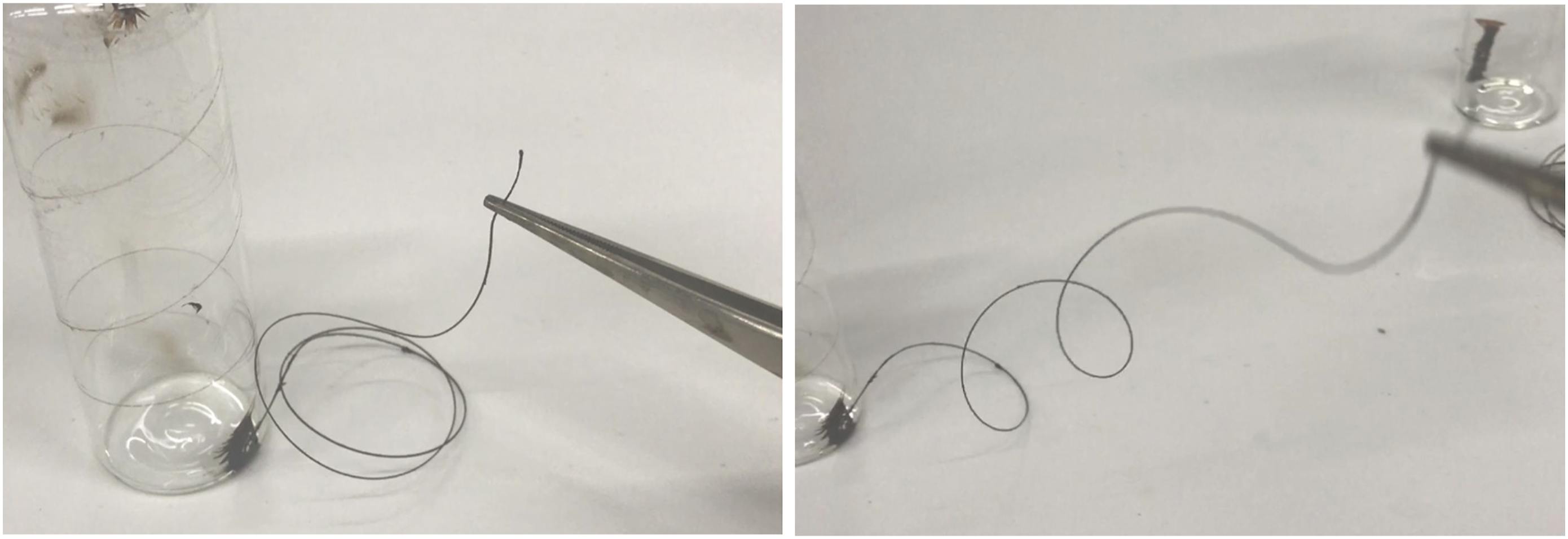
Materials characterization
The surface morphology of the samples was examined using a field emission scanning electron microscope (FE-SEM) (Zeiss-Gemini 300) equipped with a field emission electron gun operating at a voltage of 5 kV and working distances ranging from 5.4 to 8.6 mm. Nanofiber diameters were calculated using the ImageJ 1.51j8 program.
The electrochemical characterization of carbon nanofiber yarn electrodes
The electrochemical properties of CNF yarn electrodes were determined using a three-electrode configuration electrochemical workstation (CH-Instrument 608E). The reference electrode was an Ag/AgCl (1M KCl) electrode, and the counter electrode was a Pt wire. In 1
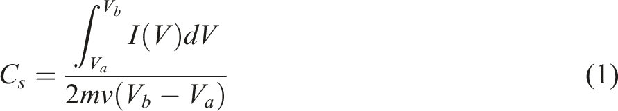
The gravimetric capacitance was measured using equation (1)56–62 and (2)63,64 for CV and GCD, respectively

Results and discussions
Figure 3 shows SEM images of PAN nanofiber yarn, stabilized PAN nanofiber yarn, and carbon nanofiber yarn. Supplementary Figure S1 illustrates the average nanofiber diameters of nanofiber yarn. Scanning electron microscope images of (a) PAN nanofiber, (b) stabilized PAN nanofiber yarn, (c) carbon nanofiber yarn. PAN: Polyacrylonitrile.
While the diameter of the PAN nanofibers was 206 ± 35 nm, after stabilization and carbonization, the nanofiber diameter decreased to 155 ± 54 nm, and yarns with an average nanofiber diameter of 123 ± 20 nm were obtained. The carbon nanofiber yarn had a diameter of approximately 360 μm. As demonstrated by SEM images, the smooth nanofiber structure was preserved after twisting, winding and thermal processing. However, unlike the carbon nanofiber surfaces shown previously,54,55 excessive breaks in the carbon nanofibers in nanofiber yarns were observed after twisting process.
Figure 4 shows Fourier-transform infrared spectroscopy (FT-IR) spectrum of PAN nanofiber, stabilized PAN nanofiber, and carbon nanofiber yarns. The very similar FT-IR spectrum was detailed discussed in our previous paper.
55
FT-IR analysis revealed that PAN nanofiber yarn was successfully stabilized, and carbonized to produced carbon nanofiber yarn.55,65 FT-IR spectrum of produced nanofiber yarns.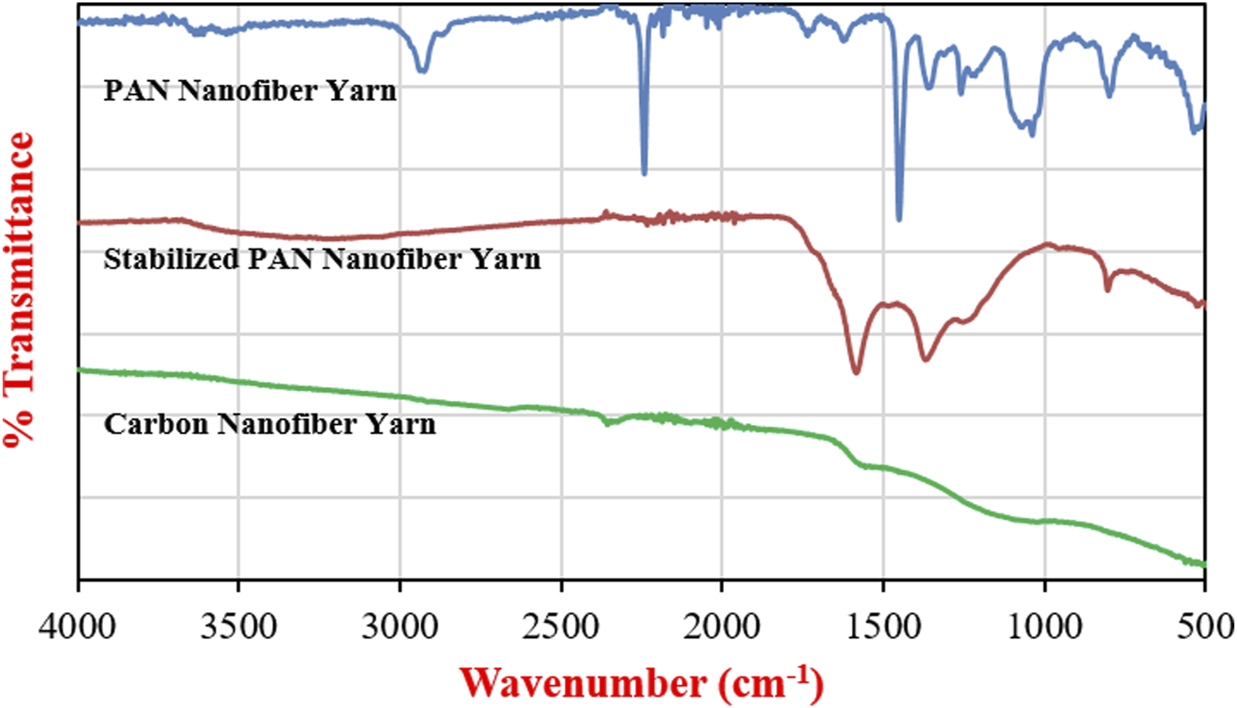
The CV curves of carbon nanofiber yarn electrodes in the 0–1V potential range at scanning rates ranging from 0.5 to 100 mV/s are shown in Figure 5(a). The scanning rate range of 0.5–5 mV/s is highlighted in Figure 5(b). The CV curves do not show any redox peaks, then which is evidence that the electrode behaves like a double-layer capacitor. On the other hand, while CV curves were close to rectangular shapes (quasi-rectangular shapes) at low scanning rate, they shifted to oval like shapes with increasing scanning rate.66,67 This change in CV curve shape at high scanning rates is indicative of poor rate performance and higher internal resistance.
68
Cyclic voltammetry curves for carbon nanofiber yarns (a) in the range of 0.5–100 mV/s scanning speed (b) in the range of 0.5–5 mV/s scanning rate.
Capacitance values were calculated using equation (1) from CV curves with a scanning rate of 0.5–100 mV/s are shown in Supplementary Figure S2. At scan rates of 0.5, 1, 2, 5, 10, 25, 50, and 100 mV/s, the specific capacitance was 80, 66, 59, 38, 29, 17, 11, and 5 F/g, respectively.
The GCD curves of the carbon nanofiber yarn electrode at current densities of 0.2–2 A/g are shown in Figure 6. Charge/discharge curves have been observed to have a nearly symmetrical shape. The values of specific capacitance calculated from the GCD curves using equation (2) are plotted in Supplementary Figure S3. Specific capacitance values of 145, 78, 53, 42, 30, and 21 F/g were calculated at current densities of 0.2, 0.3, 0.5, 1, 1.5, and 2 A/g, respectively. Galvanostatic charge/discharge curves at different current densities (a) in the range of 0.2–2 A/g current density, (b) in the range of 0.5–2 A/g current density.
In Figure 7(a), 1–10 GCD cycles are plotted. It exhibits similar charge/discharge curves throughout the cycle. The change in specific capacitance over 1000 charge/discharge cycles in the 0–1 V potential range at 1 A/g current density is depicted in Figure 7(b). The specific capacitance value of the carbon nanofiber yarn electrode increased by 20% until approximately 500 cycles, and this capacitance value was observed to be maintained thereafter. Ismar et al. observed an increase in the specific capacitance value following a charge/discharge cycle in a system containing 0.5 Galvanostatic charge/discharge cycles at a current density of 1 A/g (a) 1–10 charge/discharge cycles, (b) Cyclic stability for 1000 charge/discharge cycles at 1 A/g current density.
The equivalent-series resistance (i.e., RESR) and the charge-transfer resistance (i.e., Rct) of the CNF yarn electrode was determined by EIS and Figure 8 shows Nyquist plot of CNF yarn over the frequency range of 0.01 Hz–100 kHz at open circuit potential (0.456 V). In the Nyquist curve of ideal supercapacitors, a semi-circle in the high-frequency region and a vertical line in the low-frequency region are observed. In the high-frequency region of the above Nyquist curve, a semi-circle is observed, although it is very small. The value at which the semi-circle first intersect the Z′ curve gives the RESR, while the diameter of the semi-circle gives the value Rct.70,71 Based on the Nyquist plot, RESR and Rct was measured as 451.90 Ω and ∼9 Ω, respectively. Nyquist plots of the carbon nanofiber yarn electrode, the inset displays the zoom-in of Nyquist plots.
Conclusion
In this study, first PAN nanofiber yarns were obtained by twisting nanofiber strips with easily controllable diameters on the drum collector. Then, PAN nanofiber yarns were converted to carbon nanofiber yarns via stabilization and carbonization processes. After the stabilization process, it was observed that the unstable yarn structure became stable due to the thermal processes. The obtained CNF yarns had a yarn diameter of approximately 360 μm, and the average diameter of the nanofibers in the yarn was 123 ± 20 nm. Following that, the electrochemical performance of CNF yarns in 1
Supplemental Material
Supplemental Material - Flexible carbon nanofiber yarn electrodes for self-standing fiber supercapacitors
Supplementary Material for Flexible carbon nanofiber yarn electrodes for self-standing fiber supercapacitors by Yasin Altin and Ayse Celik Bedeloglu in Journal of Industrial Textiles.
Footnotes
Acknowledgements
Thanks to Prof. Dr Deniz Uzunsoy, Research Assistant Taha Yasin Eken and BTU-Metallurgy and Materials Engineering lab for their help on electrochemical workstation and tube furnace usage.
Author contributions
The manuscript was written through the contributions of all authors. All authors have approved the final version of the manuscript.
Declaration of conflicting interests
The author(s) declared no potential conflicts of interest with respect to the research, authorship, and/or publication of this article.
Funding
The author(s) disclosed receipt of the following financial support for the research, authorship, and/or publication of this article: This work was supported as a PhD research project by Bursa Technical University Scientific Research Project (BAP) Unit, Project Number: 172D32.
Supplemental Material
Supplemental material for this article is available online.
References
Supplementary Material
Please find the following supplemental material available below.
For Open Access articles published under a Creative Commons License, all supplemental material carries the same license as the article it is associated with.
For non-Open Access articles published, all supplemental material carries a non-exclusive license, and permission requests for re-use of supplemental material or any part of supplemental material shall be sent directly to the copyright owner as specified in the copyright notice associated with the article.