
Abstract
Electronic or conductive textiles have attracted particular attention because of their potential applications in the fields of energy storage, supercapacitors, solar cells, health care devices, etc. Contrary to solid materials, the properties of textile materials such as stretchability, foldability, washability, etc. make the textiles ideal support materials for electronic devices. Therefore, in recent years, various conductive materials and production methods have been researched extensively to make the textiles conductive. In the present study, an alternative method based on imparting the conductivity to the fiber-based structure for the production of conductive textiles was established. Considering the contribution of unique characteristics of the fiber-based structure to the clothing systems, imparting the conductivity to the fibrous structure before yarn and fabric production may help to protect the breathable, lightweight, softness, deformable and washable of textile structure, and hence to improve the wearability properties of the electronic textiles. In the study, carbon black nanoparticles were selected as a conductive material due to low cost and easy procurable while cotton fiber together with other fiber types such as polyester, acrylic and viscose rayon fibers were used due to their common usage in the textile industry. In addition, various production parameters (CB concentration, feeding rate, etc.) were analyzed and the results indicated that the developed alternative method is capable to produce conductive yarns and electrical resistance of the yarns was about 94–4481 kΩ. The yarns had comparable yarn tenacity and breaking elongation properties, and still carried conductive character even after washing. In literature, there has been no effort to get conductivity in this manner and the method can be considered to be a new application for added-on or built-in future wearable electronics. Also, in the study, produced conductive yarns were used as a collector to gather the nanofibers onto the yarn to produce hybrid yarns enabling the production of functional textile products.
Keywords
Introduction
Textile materials having electronic functionality or electrical conductivity are defined as electronic textiles. Electronic textiles (e-textiles) are the textile products that can act like an electrical circuit. Electronic textiles are used in daily life as well as health, military, and defense fields. Today, next-generation electro-textiles demand the systems directly worn on the human body and they are called as wearable electronics or wearable electronic textiles [1]. A key challenge in this field is to simultaneously acquire high conductive and wearable properties [2]. In recent years, there has been a great deal of interest in wearable electronic products.
A textile product must be conductive to be called as an electronic textile (e-textile). A variety of materials and methods are used to impart conductivity to a textile structure in the form of fibers, yarns, or fabrics. Today, conductive textiles can be obtained by (i) the use of metallic wires that are conductive by nature, (ii) the use of conductive fibers obtained by the addition of conductive materials in the fiber spinning solution, (iii) coating of fibers, yarns, and fabrics with conductive materials, and (iv) fiber spinning or coating of textile surfaces with conductive polymers. In conductive textile production, organic and inorganic materials such as metal wires, metal oxides, metal salts, conductive polymers, conductive ink, carbon nanotube, carbon black (CB), and graphene are generally used for the conductivity. Although a certain level of conductivity has been achieved with these methods and materials, they have some problems such as a hard handle, weight increase, a rigid structure, loss of fabric handle, insufficient permeability, low stability, and mechanical properties. In addition, there are still limitations regarding ease of application, large-scale production, cost, and environmental impact [3–16].
Methods and materials for the production of electronic textile products are very important in the progress in the field of conductive textiles and therefore, there is still need of research activities. In this paper, an alternative method for the production of conductive textile materials is established. The principle of developed method is based on the imparting the conductivity to the fiber-based structure having open fiber bundle form. As known, the fiber-based structure used in clothing systems has unique characteristics such as softness, lightweight, breathable, deformable, washable, and durable to mechanical deformations such as bending, twisting, and stretching. Therefore, they can also be seen as an ideal as the platforms for future wearable electronics [17,18]. Compared with widely used and known materials such as conventional silicon-based, thin-film-based electronic devices or coated structures, devices obtained from fiber-based assemblies can have unique abilities such as stretching, twisting, bending, and draping. Also, the occurrence of crack, delamination, crack propagation and loss in electronic functions can be prevented. Furthermore, fiber assemblies can be added-on or directly used for built-in electronic materials. Due to possible progress in fabric comfort, wearability properties, and potential applications, this study focused on developing a method to create fiber assemblies having a conductive function. In the method, firstly, a solution was prepared with a conductive material. Following the preparation process, the conductive solution was applied to the staple textile fibers, and then, yarn production was realized by the known yarn spinning system. Therefore, the textile structure was being conductive before the yarn and also fabric production. Different from the present methods such as blending with metallic wires, impregnation, or coating, the developed method is believed that imparting the conductivity at the fiber form might protect the porous and flexible structure of textile materials. It is also thought that the staple spinning method provides flexibility and porosity and this case might help to get soft and breathable material. There has been no effort, as yet, to get conductivity in this manner. Therefore, the developed method can be considered to be a new application in the functional yarn production and yarn spinning field.
Experimental details
Material
In the study, CB powder was purchased from NanoGrafen firm (Turkey) for the conductivity and was dissolved in ethanol (supplied from Sigma Aldrich, Mw = 46.07 g/mol and ≥99.9% purity) with the help of the mechanical stirrer and ultrasonic bath (Table 1). During the preparation of the conductive solution (Figure 1(a)), it was given importance to decrease the agglomeration to improve the dispersion of the CB powder in the solution. Therefore, different preparation processes based on mixer type and stirring time, and also various concentrations based on the usage of ethanol and CB were tried. After the experiments, stirring time over 1 h and usage of both mixer types were decided as optimum preparation process and CB concentration was fixed at 0.5%, 0.75%, and 1.0%. Following the preparation process, the resulting dispersions were used for conductive spun yarn production. Dispersions were fed to the fiber bundle and ring spun yarns were produced on Rieter G10 conventional ring spinning machine; 100% cotton, polyester, acrylic, viscose, and cotton-polyester blended fibers were used for yarn productions. Fiber length was 32 mm for cotton fiber, and 38 mm for polyester, acrylic, and viscose fibers.
CB powder properties.


Conductive yarn production on classical ring spinning yarn technology.
Method
In order to apply the conductive material dispersion comprising CB nanoparticles and ethanol solvent to the cotton fiber bundle, a special feeding apparatus consisting of a feed pump and a nozzle has been designed (Figure 1(b)). The feed pump (1) is responsible for supplying the conductive solution to the fiber bundle in the desired amount and a controlled manner, while a nozzle/syringe (2) was used for the application of the mixture to the open fiber bundle. The feed pump was also used for nanofiber spinning with electrostatic fiber spinning method. The feeding apparatus developed for conductive dispersion application is portable and can be placed at the desired application point. In the production of conductive functional yarn, the ring spinning method was preferred because it is the most widely used yarn spinning technique in the world, and it can be found almost in all spinning mills. During yarn production, the main focus was to apply the conductive solution to the open fiber bundle form rather than the twisted and compact yarn form. Therefore, it was given importance to apply the solution before the yarn formation. In order to realize this case, portable feeding apparatus was placed in the drafting system of the ring spinning machine. As known, during the ring spun yarn production, a roving, which comes from the bobbin is passed from break to main drafting zones to get the desired yarn fineness, and then, twisted with spindle-ring-traveler, and wound on to the cops. In the production of conductive functional spun yarns, roving was break-drafted and opened its twist. When the fiber bundle come to main drafting zone, conductive dispersion was given to the opened fiber bundle with the syringe in a certain amount provided by the feeding pump (Figure 1(c)). Then, fiber bundle comprising CB nanoparticles was twisted by ring-traveller-spindle and wound on to the cops as in classical ring spinning (Figure 2). In this developed method, application at the main drafting region could allow the operating the conductive material to the outer and also inner parts of the fibers. Additionally, it is required to state that any type of dispersion depending on the desired functional properties can be given to staple fibers. Therefore, the developed method was named as an alternative functional yarn production technique on staple spinning system.

Pure ring spun yarn (a) and CB particle doped (b) ring spun yarn.
In the study, it was analyzed the effect of various production parameters on an alternative yarn production method and yarn conductivity. Effect of fiber type and yarn count parameters were investigated to determine whether there are any limitations of the alternative production method. In addition, the feeding rate of the conductive dispersion, the amount of CB in the dispersion and spindle speed were also researched to understand the influences of these parameters on yarn conductivity. Cotton, cotton/polyester, polyester, acrylic, and viscose rovings were used. Ne 16/1 and Ne 30/1 yarns were produced (Table 2). Feeding rates between 40,000 and 120,000 mL/h and 0.5%, 0.75%, and 1.0% CB nanoparticle amounts were used. Yarn productions were realized on Rieter G10 conventional ring spinning machine (Figure 3).
Conductive yarn production parameters.


Conventional Rieter G10 (a) and modified (b) ring spinning machine.
Nanofiber coating on textile based collector
In another part of the study, CB nanoparticle doped yarns were used as a collector for the electrostatic spinning of the nanofibers. In recent years, physical finishing has gained much popularity to give functional features to textile products. One of the various physical finishing methods is the electrospraying and electrostatic spinning. Electrospraying/electrostatic spinning are flexible techniques due to their capability of nanofiber coating onto fibrous textile structures, particularly fabrics, filaments and yarns, and textile products are going to be produced having different functionalities [19–21]. As known, the electrostatic spinning method consists of three main components: a high-voltage power supply, a spinneret/syringe, and a grounded collector. In electrostatic spinning, polymer solution fed through the spinneret at a constant rate is spun into smaller diameter fibers by electric field provided a high voltage power supply, and electrically charged fibers are directed towards the oppositely charged collector placed under the spinneret to collect the fibers. In electrostatic spinning, conductive materials, mainly metal-based surfaces are often used as a collector [21]. In literature, there are also some studies to deposit nanofibers on yarns/filaments and hence hybrid fibrous structures were obtained. Scardino and Balonis [22] and Zhou et al. [23] collected electrospun nanofibers onto the filament surface while Bazbouz and Stylios [24], and Thorvaldsson et al. [25] gathered onto the surface of microfiber. Dabirian et al. [21] carried out nanofiber coating by a metal disk worked as a collector. As different from the previous studies, He et al. [26] used a multi-nozzle jet electrospinning device for the production of nanofiber coated hybrid yarns. Yalcinkaya et al. [27] used a modified roller electrospinning system covering the PES textured filament core yarn with nanofibers. Similar to this study, Jiang et al. [28] used carding web as a collecting material different nozzle type consisting of a stepped pyramid stage to deposit antibacterial nanofibers onto the web and then, nanofiber/cotton hybrid yarns were spun from the produced web for the fabricating the antibacterial knitted fabric.
Differently from the previous studies, in our study, conductive yarns produced with developed alternative functional yarn production method were used as a collector for the nanofiber coated yarns. Nanofibers were collected onto the conductive yarns, and the produced yarns were called a hybrid yarn. Hybrid yarn has been able to carry the characteristics of spun yarn and functionality of nanofibers in one structure. A combination of these two different structures might enable us to take the advantages of structural integrity and mechanical properties of conventional spun yarns and also desirable high surface area and the functionality of electrospun nanofibers. In order to produce the nanofiber coated hybrid yarn, Ne 16/1 cotton and Ne 30/1 acrylic staple spun yarn doped with 0.5% CB nanoparticles (at 60,000 mL/h feeding rate) were used as a textile-based collector.
For the nanofiber spinning, polyacrylonitrile (PAN) polymer (Sigma Aldrich, bulk density 0.34–0.39 g/cm3) was used. Without any further treatment, N,N dimethylformamide (DMF, 98%, Merck Co., Germany) was used as a solvent to prepare the polymer solution. Neat PAN solutions (6 wt %) were prepared by dissolving PAN granules in DMF at room temperature for 6 h with a mechanical stirrer. Before the electrospinning process, conductive yarns (1) doped with CB nanoparticles were hung between two bobbins, as shown in Figure 4. For the nanofiber spinning, it was used a well-known electrospinning device consisting of high voltage DC power supply (0–22 kV), feeding unit (2) and syringe (3). PAN solution was fed to the syringe and high voltage was applied. The produced electrospun nanofibers were collected onto the conductive yarns for 5 min. The spinning parameters were that voltage was 14 kV, feeding ratio was 1.00 mL/h, and the distance between the syringe and middle point of fiber bundle was 15 cm. The length of the collector was 30 cm. Optical microscope (ASC 4/0.1-Motic) and scanning electron microscope (SEM, Philips XL-30S FEG) were employed to check and analyze the morphological characteristics of nanofiber coated hybrid yarns.

Nanofiber coating on a CB doped yarns.
Characterization of conductive yarns
Within the scope of the study, characteristics of CB doped yarns together with electrical conductivity were tested.
Yarn appearances
In the study, yarn images were taken to detect the presence of conductive material in the yarn structure. Furthermore, the distribution of the CB particle was also observed. SEM was used to analyze the morphological characteristics of the yarns with an accelerating voltage of 4 kV and a current of 10 µA at a high magnification power.
Electrical resistance
Electrical resistance is the physical property of a material, which is a measure of the ability of electrons to flow through it when a voltage is applied across two points on the material (AATCC, 2005). The inverse of the conductivity is called resistivity. In the study, the electrical resistance of the produced yarns was determined by AATCC Test Method of 84-2005 [29]. According to AATCC test method, yarn specimens are conditioned at specified relative humidity and temperature. The electrical resistance of the yarn held between two electrodes is measured by the use of an electrical resistance meter (Figure 5(a)). Tension is applied to the probes to hold the strands straight. It allows the current to pass through the sample for a minimum period of 1 min and until a constant reading is obtained. According to AATCC Test Method, at least, 10 measurements should be done on the single strands in order to determine the uniformity of resistance along a single end of the yarn. The results are expressed as resistance per unit of length per yarn strand, ohms per measured length (4 mm etc.). In this study, the resistance between the yarn ends was tested by Digital multimeter having two probes. However, there were serious problems during the measurements. One of the problems was that resistance values changed depending on the tension applied by the user to the probes. Another one was that the probes did not contact the yarn exactly. Therefore, accurate, precise and stable measurements could not be realized. In order to obtain accurate values, two probe method was modified. In the modified method, probes were passed through an arm to fix the probes during the measurement, and thus it was possible to contact the probes with the yarn directly (Figure 5(b)). With the developed method, there is no need of user and tension applications during the measurement. Before the measurement on the modified multimeter device, the yarn sample (1) was placed through the slot (2). Then, each probe (3) of the multimeter (4) was passed inside the hole and contacted to the yarn sample (Figure 5(b)). Samples were air-conditioned and measurements were carried out at 20°C, 65% RH. The resistance of samples was measured at 4 cm distances between the ends of the yarn samples. In the study, 20 measurements were realized for each concentration, and mean values were calculated to express the electric resistivity of samples.

Measurement with known (a) and modified (b) two probe method.
Effect of washing process
Today, in addition to the high electrical conductivity level, one of the expected properties from electronic textiles is to protect the conductivity characteristic against the washing effect during the usage of conductive textile structures. Therefore, in the present study, effect of the washing process on the conductivity values of the yarns was investigated. Ne 16/1 CB nanoparticle doped yarns were wound as skein form by yarn wheel and washed at three different washing conditions by Gyrowash laboratory washing machine. Washing processes were realized at 40°C–20 min, 40°C–30 min, and 60°C–10 min. Electrical resistance values of the unwashed and washed yarns were measured by two probe method and the results were compared.
Tensile properties
Tensile properties were also tested to determine the effect of conductive material on the yarns. Strength and breaking elongation properties of the conductive yarn samples having CB particles were tested by Llyod LR5K Plus electronic tensile tester at under standard atmospheric conditions (20°C and 65 RH%). The standard test method of ASTM D 2256 was followed and the gauge length and the crosshead rate was 500 mm and 500 mm/min, respectively [30]. Ten samples were tested and the average values were calculated as breaking strength and elongation of the samples. Test results were analyzed statistically by SPSS 16.0 statistical software to determine any significant differences. To deduce whether the parameters were significant or not, p values were examined. If the value is >0.05 (p > 0.05), the difference will not be important and should be ignored.
Results and discussion
The results were given below and ring spun yarn without CB was named as pure and undoped ring spun yarn while the yarn comprising CB was called as conductive and doped yarn.
Yarn images
Yarn images of the cotton ring spun and CB doped cotton yarns are given in Figures 6 and 7.

SEM images of the 100% cotton Ne 16/1 ring spun yarn.
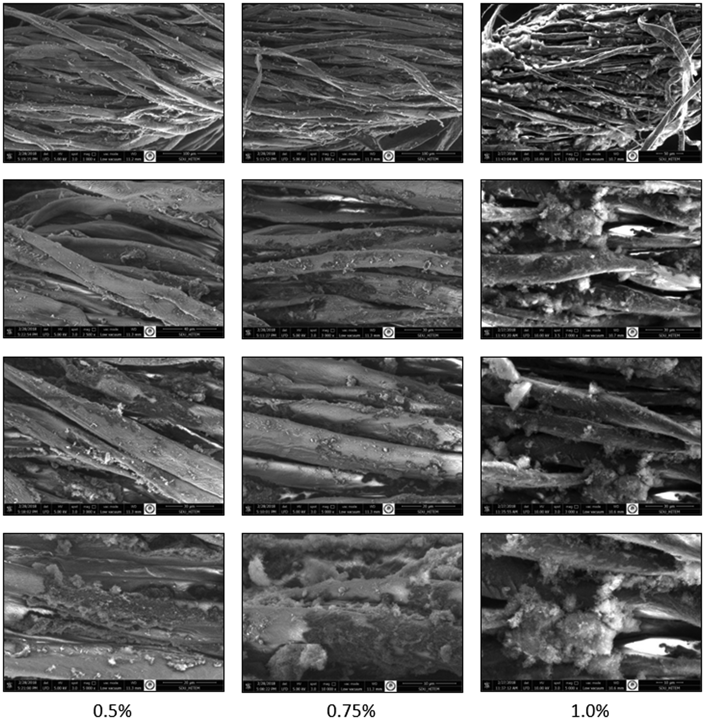
SEM images of CB dispersion applied Ne 16/1 cotton ring spun yarns for different magnifications (at the 60,000 mL/h feeding rate).
As seen in Figures 6 and 7, comparing with the images of untreated ring spun yarns, the presence of the carbon particles in the dispersion employed to the yarns could easily be seen on the yarn surface. The amount of CB particles on the fiber surface were getting increased with the higher CB concentrations. In addition, it was observed carbon particles tend to agglomerate at high concentrations, particularly for 1.0%. Cotton fibers in pure and CB doped ring spun yarns had helices along the fiber length. On the other hand, cotton fibers in the yarns produced with the alternative method followed a helical path due to the real-twist given by ring-traveler during the spinning process, as in classical ring spun yarns. Therefore, it was concluded that conductive cotton yarns produced with alternative method still carry the ring spun yarn character. In the study, yarn productions were realized with different yarn counts and fiber types. As seen in Figure 8, SEM images of Ne 30/1 cotton yarns also indicated the presence of CB particles on the yarn surface, and the yarns also showed ring spun yarn character.

SEM images of CB dispersion applied Ne 30/1 cotton ring spun yarns.
Yarn conductivity
In this part of the study, CB dispersion was applied to Ne 16/1 cotton ring spun yarns, and electrical resistance of the produced yarns was measured by modified two probe method. The electrical conductivity of the produced yarns was expressed with electrical resistance values. In the study, the effect of various production parameters on yarn conductivity was also analyzed to have an idea about the process parameters of the alternative method.
Effect of CB concentration
In this part, three different CB concentrations were used in the dispersion, and the results were analyzed for three different feeding rates to get more values. As seen in Figure 9, most of the cotton ring spun yarns doped with CB particles had electrical resistance values. However, no conductivity value was detected in untreated cotton ring spun yarns, and the yarn produced with the lowest feeding rate (40,000 mL/h) and CB concentration of 0.5%. As known, the lower resistance value is required for high conductivity. However, it is worth mentioning that multimeter can capable to measure the electrical resistance values within a certain range. Therefore, no resistance value indicates that there is no conductivity. The reason for this case is considerably high resistance value of the sample above the measuring range of the device. Therefore, the resistance value of the sample produced with the lowest feeding rate (40,000 mL/h) and CB concentration of 0.5% was beyond the measuring bounds of the device and the electrical conductivity was considerably low to be negligible. Therefore, almost all doped yarns obtained with the alternative method showed conductivity property. When the changes in resistance values were examined, it was found that resistance decreases and hence conductivity increases with the higher CB concentration, as expected.

Electrical resistance values of the Ne 16/1 untreated and doped cotton ring spun yarns.
Effect of feeding rate
In order to analyze the effect of the feeding rate, five different feeding amounts were used when the CB particle concentration was kept constant at 0.5%. According to Figure 10, electrical resistance values displayed a decreasing trend up to 90,000 mL/h feeding rate, and the conductivity of the yarns was getting better. The least electrical resistance and hence the highest yarn conductivity was determined at 90,000 mL/h. However, resistance values started to increase and conductivity of the yarns was getting worse with the higher feeding of conductive dispersion than 90,000 mL/h. Therefore, this result indicated that there is a certain limit for dispersion feeding rate in order to obtain the highest conductivity.

Electrical resistance values of the Ne 16/1 doped cotton ring spun yarns for different feeding rates.
Effect of spindle speed
In another part of the study, it was aimed to research the relationship between spindle speed and feeding rate of CB dispersion. Three different spindle speed values were used for two different feeding rates, and hence the effect of spindle speed on yarn conductivity was also investigated. The electrical resistance results of the yarns are given in Figure 11. As expected, resistance values of the CB doped yarns increased with the higher spindle speed values. It was thought that the reduction in yarn conductivity might result from less interaction time of the fibers with conductive dispersion. However, an interesting case was observed when the results were examined. As the feeding rate was increased, lower resistance values were obtained for three spindle speed values. At 90,000 mL/h feeding rate, the lowest resistance and hence the highest electrical conductivity values were obtained even at the highest spindle speed. The resistance value of 90,000 mL/h feeding rate at 7500 rpm was about equal to that of 74,000 mL/h feeding rate at 5500 rpm. Therefore, this result meant that spindle speed and production rate could be increased with feeding rate values in addition to nanoparticle concentration.

Electrical resistance values of the Ne 16/1 doped cotton ring spun yarns for different spindle speed values (0.5% CB concentration).
Effect of fiber type and yarn count
In the last part of the study, we aimed to evaluate the performance of alternative production method using different fiber types. Therefore, in addition to cotton fibers, CB dispersion was applied to 70/30% cotton/polyester, 100% polyester, acrylic, and viscose rayon fibers. In present work, it was also aimed to determine whether the alternative method is capable to produce finer or coarser yarns. Therefore, in addition to Ne 16/1 yarn count, it was produced Ne 30/1 yarns with cotton fibers. During the yarn production, CB concentration (0.5%) and feeding rate of dispersion (74,000 mL/h) were kept constant when the fiber type and yarn count was changed. As seen in Figure 12, a certain amount of electrical resistance values were determined at all fiber types. The lowest resistance was observed in 100% cotton and also acrylic fibers while the highest was in 100% polyester fibers. Therefore, cotton and acrylic fibers provide better electrical conductivity than other fibers. Particularly, the hydrophobic structure of the polyester fibers was thought to cause lower conductivity results. On the other hand, acrylic fiber has also hydrophobic character. However, its conductive feature rather than its hydrophobic structure might help to have comparable electrical conductivity values with cotton and viscose rayon fibers. Regarding the effect of yarn count, a certain amount of electrical resistance values were measured at both cotton yarns having different yarn counts. Resistance values were about 5 kΩ for Ne 30/1 while it was 450 kΩ for Ne 16/1. As a conclusion, the electrical resistance results of the CB doped yarns indicated that developed alternative method allows producing the conductive yarns using with various fiber types having different yarn counts.

Electrical resistance values of the CB doped ring spun yarns for different fiber type and yarn count.
Effect of washing process
In order to investigate the effect of washing on yarn conductivity, Ne 16/1 CB nanoparticle doped yarns were wound as skein form by yarn wheel, measured their electrical resistance by two probe method, and then, washed at three different washing conditions by Gyrowash laboratory washing machine. Washing processes were realized at 40°C–20 min, 40°C–30 min, and 60°C–10 min. After washing, the electrical resistance values of the washed yarns were measured by two probe method, and compared with their unwashed conditions. The results were given in Figure 13. As seen, all washed yarns had higher resistance and hence lower conductivity values than that of the unwashed yarns. As expected, the washing process led to a decrease in the conductivity of the doped yarns. However, the doped yarns produced by alternative method still carried conductivity property. After washing, resistance values increased between 1.5 and 3 times. As the temperature and washing time were increased, the increases in resistance values decreased and better yarn conductivity values were obtained. Particularly, considering the results at 40°C, resistance values increased more with the higher washing duration. Comparing with the washing temperature, washing duration seemed to be more effective on electrical resistance values.

Electrical resistance values of the CB doped Ne 16/1 cotton ring spun yarns (produced at 1.0% CB concentration and 60,000 mL/h feeding rate).
Tensile properties
In order to analyze the effect of CB dispersion application on tensile properties of the yarns, tenacity, and breaking elongation of pure and doped Ne 16/1 cotton ring spun yarns were analyzed. The results of both yarn types were compared. As seen in Figure 14, all doped cotton yarns with CB particles had higher yarn tenacity values than that of the untreated ring spun yarns. According to Table 3, there were statistically significant differences in the tenacity values of the yarns. Hence, CB particle applied yarns with the developed alternative method were significantly stronger than normal cotton ring spun yarns. The differences in tenacity values of treated and untreated yarns were about 15–25%.

Tenacity results of Ne 16/1 untreated and CB particle doped cotton ring spun yarns.
Analysis of variance test results of tensile properties.

*The mean difference is significant at the 0.05 level.
When the effect of the CB concentration on yarn tenacity was examined, it was determined that the tenacity of the doped yarns increased by up to 0.75%. However, tenacity values started to display a decreasing trend as the concentration was increased from 0.75% to 1.0%. These cases were observed for all feeding rate values. However, the lowest yarn strength values were obtained at 0.5% concentration at all doped yarns. When the results were analyzed statistically, in particular, there were no significant differences between 0.5% and 0.75% concentrations comparing to that of 0.5% and 1.0%, 0.75% and 1.0%. Therefore, it could be concluded that 0.75% is a critical concentration level for yarn tenacity.
As for the effect of feeding rate, a similar result was observed and the strength of the yarns increased with higher CB dispersion feeding values. However, in comparison to the effect of CB concentration, there were not considerably changes in the tenacity values. In literature, Kaynak et al. [31] stated for composites containing CB that the ultimate strength increased with carbon-black concentration. The reason for this case might be reinforcing characteristic of CB. However, the addition of filler resulted in stress concentration and led to lower strength values. Therefore, our findings have coincided with this study. Gojny et al. [32] worked on the application of nano-particle reinforced epoxies as matrix (containing CB and CNTs) for conventional glass-fiber-reinforcements. In the study, it was determined less significant improvement in tensile strength of the composites containing 0.3 wt % nano-filler, compared to the lower filler contents (0.1% and 0.2%). This case was explained by the increasing amount of agglomerates, and it was stated that these agglomerates indeed act as imperfections in a composite. This case can induce an untimely failure when the interfacial adhesion to the surrounding matrix is poor. Additionally, Sarkar et al. [33] used natural rubber latex (NRL) and polyvinyl alcohol (PVA) containing CB as the conductive filler to make flexible, durable conductive cotton fabric by the coating process. Plain woven cotton fabrics were coated by knife-over-roll coating technique, and it was found that an increasing dose level of the CB in the composite is being contributed towards the increment of tensile strength <1%. Additionally, it was determined that at the constant level of PVA, tensile strength initially increases then decreases with higher doses of CB particles. Therefore, the authors stated that the inclusion of the filler into the composite results in the enhancement of the tensile characteristic of the composite up to a certain limit, and it is detrimental to the tensile properties beyond the limit. Thus, it was concluded that at higher loading of CB, may not contribute to the increment in the tensile strength. Therefore, reinforcing characteristics of CB might make a contribution to get better tenacity values up to 0.75% CB concentration. However, the stress-concentration effect might be dominant at higher content of CB particles, and this case led to lower yarn tenacity values. CB doped yarns could be thought as a composite yarn due to the presence of different material in yarn structure. In composites, mechanical properties depend on the filler type, the filler aspect ratio, the moduli of the filler and the matrix, filler-matrix interface, etc. Therefore, composite yarn produced in this study might be affected by filler properties like composites [31].
Breaking elongation of the yarns obtained with alternative and classical ring spinning methods was compared, and the results are shown in Figure 15. According to the values, cotton ring spun yarns doped with CB particles had lower elongation values than that of the untreated ring spun yarns. The difference in elongation values of untreated and all treated yarns was found statistically significant (Table 3). Breaking elongation values of cotton ring spun yarns were about 10% while they were about 8–9% for doped yarns. When the effect of particle concentration and feeding rate parameters was examined, it was not observed a clear trend and the results changed depending on particle concentration and feeding rate of the dispersion. In order to sum up the results in general terms, breaking elongation values of the yarns decreased as the CB particle amount increased with higher particle concentration and feeding rate values. In literature, Kaynak et al. [31] stated similar findings for CB containing composites and indicated that elongation at break values decreased sharply with the filler content for all types due to the stress–concentration effect. Furthermore, elongation values might be decreased to some extent due to the incorporation of the rigid filler into yarn structure.
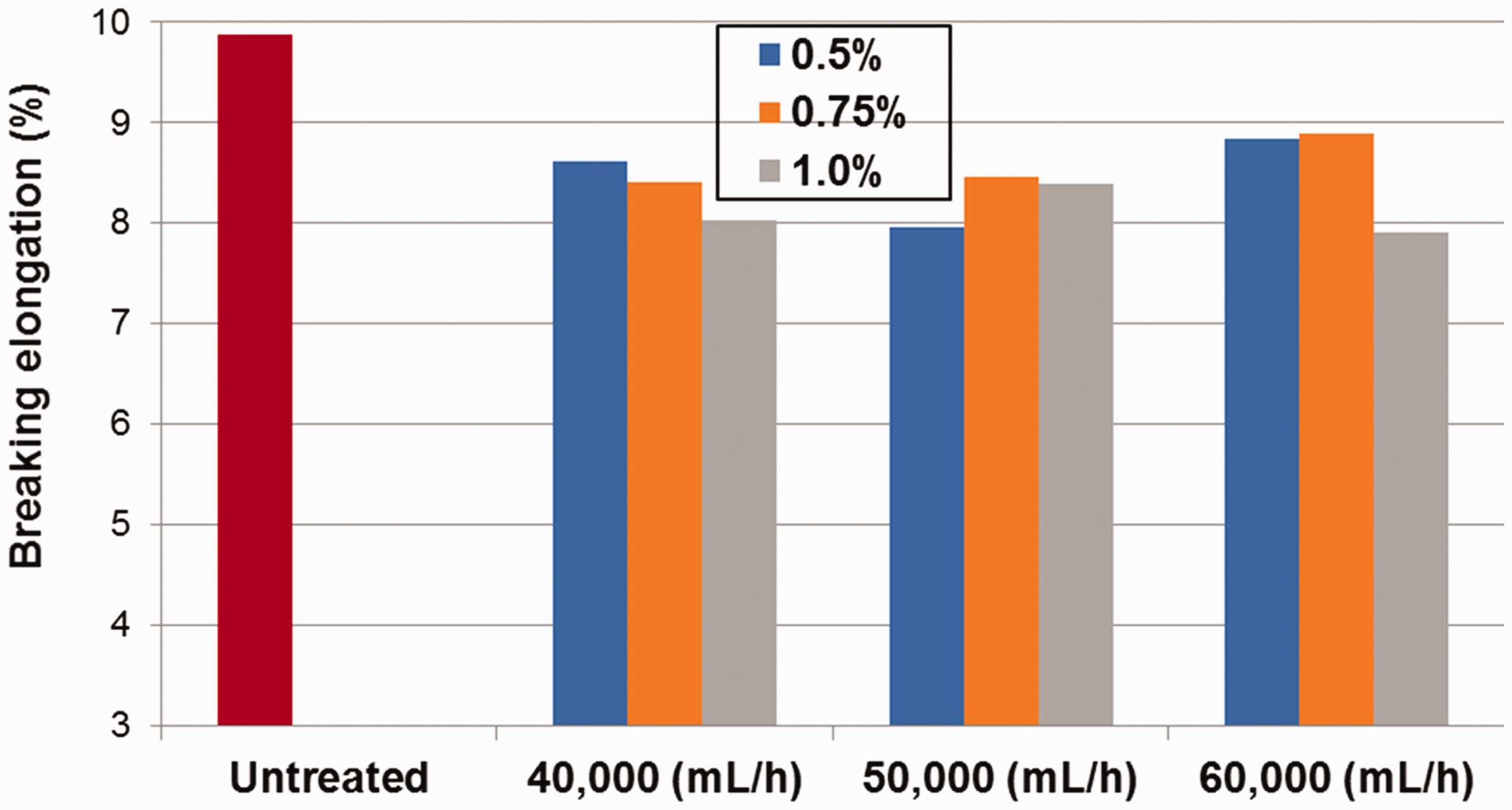
Breaking elongation results of Ne 16/1 untreated and CB particle doped cotton ring spun yarns.
Nanofiber coating on textile based collector
In the last part of the study, CB nanoparticles doped yarns (Figure 16) were used as a collector for the electrostatic spinning of the nanofibers and coated by electrospun PAN nanofibers. The produced yarns were called as a hybrid yarn due to comprising characteristics of the staple spun yarn together with electrospun nanofibers.

CB (0.5%) doped 100% Ne 16/1 cotton (a) and Ne 30/1 acrylic yarn (b) images (60.000 mL/h feeding rate).
Optical microscope and SEM images of the nanofiber coated hybrid yarns are given in Figures 17 and 18. As seen in Figure 17, CB doped cotton and acrylic yarns were covered by electrospun nanofibers, and therefore it could be thought that doped yarns could collect the nanofibers onto their surface due to their conductivity. On the other hand, optical images also indicated that the doped yarns were almost completely covered by the nanofibers, and the coated surface area of the nanofiber was increased as the coating time increased from 1 min to 5 min. Nanofibers were almost observed all the yarn body. In addition, helical streamlines of the doped yarns could be seen, and therefore nanofiber coated hybrid yarn still protected spun yarn characteristics due to real-twist given by the ring spinning. However, in coated yarns, it was observed that there were some cracks along the yarn length, and they distributed locally along the yarn length.

Optical microscopes images of nanofiber coated cotton (a) and acrylic (b) hybrid yarns.
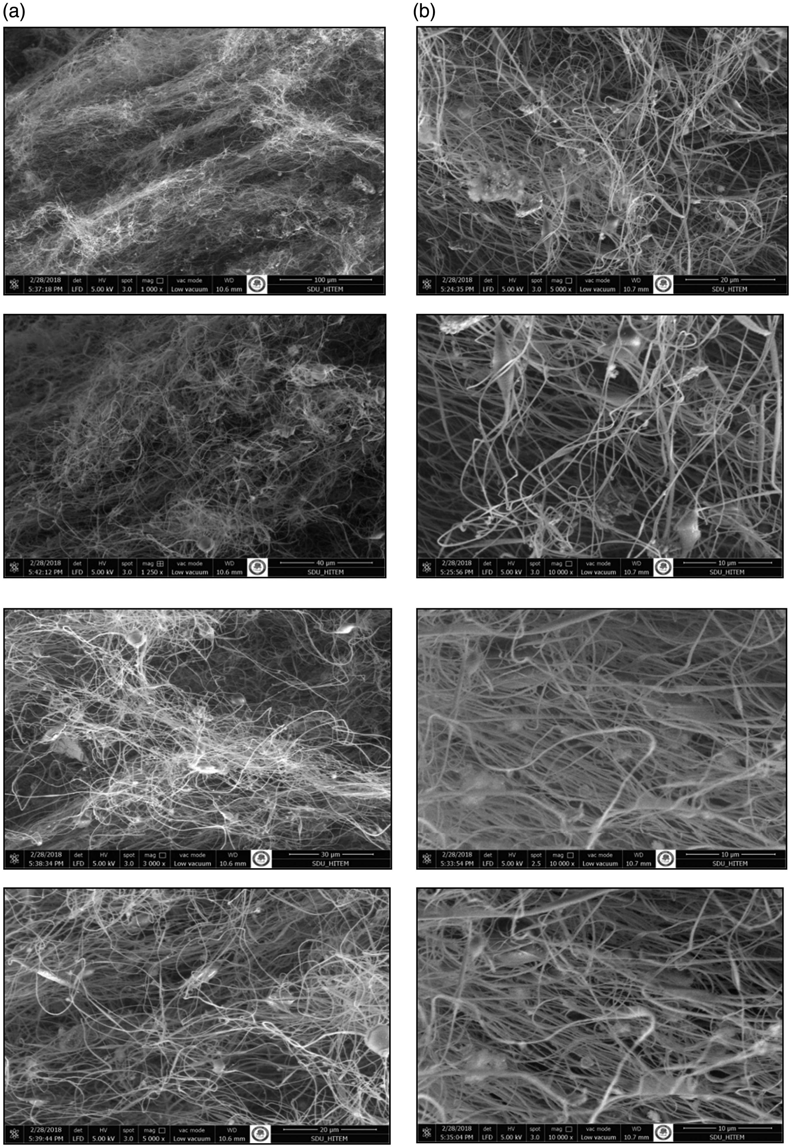
PAN electrospun nanofibers on the CB doped cotton (a) and acrylic (b) yarns.
When the SEM images of nanofibers were analyzed, it was determined that nanofibers were distributed randomly on CB doped yarns and the diameter of the nanofibers was seen as uniform distribution (Figure 19). Fiber diameter values were measured as 246.54 nm and 212.55 nm for cotton and acrylic yarns, respectively. On the other hand, it was observed bead formation resulted from a polymer which has not been converted to nanofiber form.

Diameter distribution of PAN nanofibers on the CB doped cotton (a) and acrylic (b) yarns.
Conclusions
With the progress in technology, there is a great deal of interest to electronic textiles, particularly wearable electronics (e-textile) to meet the technological demands of modern society. One of the main elements for e-textiles is the usage of electrically conductive fibers, yarns, or fabrics to provide the signal transmission between the garment and other segments such as sensors, actuators, or computer chips, which are embedded into textile product [11]. To ensure conductivity, various methods have been used. However, these methods have still some shortcomings about excellent electrical properties with stability, ease application, low cost, and wearability. In the present study, it was worked on the development of an alternative method based on conformal coating of fiber-based structure. In the method, appropriately prepared dispersion comprising conductive material (CB nanoparticles) is applied to any types of open staple fiber (cotton, polyester, acrylic, viscose rayon, etc.) by specially designed feeding system during the yarn production. Then, fiber bundle is twisted by the spindle-ring-traveller system of the ring spinning method. With the contribution of application on opened fibrous structure, the conductive material can be doped to both the outer and inner parts of the yarns. SEM images of the produced yarns also indicated the presence of CB nanoparticles through the yarn structure. Additionally, conductive cotton yarns produced with alternative method still carry the ring-spun character. The textile structure is being conductive before the yarn and thus fabric production. Two-probe conductivity measurements of the yarns also showed that electrical resistance values of the yarns varied about 94-4481 kΩ depending on production parameters such as conductive material concentration and feeding rate of the dispersion. Even an increase in electrical resistance of the produced yarns after washing process, the yarns still carried conductivity property. Therefore, the developed method enhanced to impart certain level of the electrical conductivity to the ring spun yarns. Additionally, the ring spun yarns produced with the developed alternative method were significantly stronger than normal cotton ring spun yarns. When the breaking elongation values of the yarns were analyzed, it was determined that the yarns produced with developed method had about 8–9% while the yarns produced by the classical ring spinning method had about 10%. Therefore, conductive yarns obtained with the developed method had comparable yarn tenacity and breaking elongation properties. On the other hand, in the study, the effect of various production parameters on electrical resistance were researched and the least resistance value (94 kΩ) was determined at 90,000 mL/h feeding rate, 0.5% CB concentration and 5500 rpm spindle speed. Electrical resistance decreased and yarn conductivity increased with the higher CB concentration (from 0.5% to 1.0%) and up to certain limit of the dispersion feeding rate (up to 90,000 mL/h). Spindle speed and production rate could be increased with proper production parameters such as feeding rate values in addition to nanoparticle concentration. The alternative method is capable to work with different yarn counts and various fiber types.
Different from the present methods such as impregnation or coating, both imparting the conductivity to the fibrous structure prior to yarn and fabric production and the spun yarn character are thought to contribute to the preservation of the porous and flexible structure of textile materials. This case may help to enhance the breathable, lightweight, softness and deformable of fabric structure and hence to improve the wearability properties of the electronic textiles. Contrary to the events such as crack occurrence, delamination, loss in electronic functions, etc., working with fibrous structure in the developed method may be useful to obtain a certain level of conductivity with good electrical stability. On the other hand, usage possibility as a yarn or fabric form will provide new opportunities for added-on or built-in electronic materials. In the study, the produced yarns were used as a collector during the electrostatic spinning to take advantages of conventional spun yarns and electrospun nanofibers in one structure and it was succeeded to produce hybrid yarn. Lastly, taking into the consideration of opportunities of the developed alternative functional yarn production method, it is believed that various conductive materials, auxiliary chemicals, and process parameters should be researched to improve the conductivity, stability and other textile characteristics such as washing resistance, etc.
Footnotes
Declaration of conflicting interests
The author(s) declared no potential conflicts of interest with respect to the research, authorship, and/or publication of this article.
Funding
The author(s) disclosed receipt of the following financial support for the research, authorship, and/or publication of this article: This work was supported by Scientific Research Fund of the Suleyman Demirel University (Project Number: 4644-YL2-16 and Project Number: FYL 6955).