
Abstract
This paper presents an innovative, eco-friendly and sustainable tape manufacturing technology that transforms waste carbon and polyamide fibers into a new class of fibrous structure with unidirectional fiber orientation, termed “unidirectional tapes structure” for the fabrication of high performance composites. This novel technology imparts homogeneity, uniformity, orientation and thermal stability in unidirectional tapes structure that resemble conventional prepreg material. Unidirectional configuration of the tapes structure brings a revolution towards development of cost efficient carbon fiber composites for load bearing structural applications. This paper introduces the concept of tape manufacturing technology and highlights the modifications, optimization, and technological developments carried out to develop unidirectional tapes. The structural parameters that play a significant role in the properties of the high performance composite, such as fiber length, fiber orientation, fiber damage, and uniformity, were assessed during tape manufacturing. The results reveal composites fabricated from unidirectional tape structures with optimum parameters deliver tensile strength and modulus of 1370 ± 22 MPa and 85 ± 4 GPa, respectively.
Keywords
Introduction
Global demand for carbon fiber reinforced plastics is growing in multiple engineering fields, including aviation, aerospace, automotive, sports, and wind energy sectors because of light-weighting potential and exceptional mechanical properties. 1 It is expected that the consumption of carbon fiber reinforced plastics will reach up to 200 kilotons by the end-of this decade. 2 The mechanical properties that make carbon fiber reinforced plastics one of the most demanding and futuristic material is high specific strength, high specific stiffness and low weight as compared to conventional high performance materials, for example, steel. 3 Besides this, light-weighting potential of carbon fiber reinforced plastic can reduce fuel consumption in aviation and automotive sector but also protect eco-system by reducing CO2 emissions.4–7 Moreover, it also helps to fulfill the new standards implemented by EU regarding emission of greenhouse gasses. 8
Unfortunately, manufacturing of carbon fiber reinforced plastics generates an exorbitant amount of waste, originating from two major categories, for example, manufacturing waste and end-of-life components. Manufacturing waste produced from the composite industry can be further classified into dry waste and resin impregnated waste. Dry waste comes from production offcuts, left over spools, trimmed fabrics and bobbin ends. The resin impregnated waste or wet waste, for example, originates from out-of-date prepreg waste. The end-of-life waste is retrieved from retired components, for example, aircraft wings and wind turbine blades.9,10 USA, UK, and German composite industries are collectively generating 11 kilotons/year carbon fiber reinforced plastic waste. 11 Within the upcoming decades, multiple industries are expected to produce massive waste in the category of end-of-life waste. It is estimated that waste obtained from end-of-life components will reach up to 50 kilotons per year in 2030. 12 Therefore, there is enormous demand in order to manage this waste with sustainability. 13
Conventionally, waste management techniques, for example, landfilling or incineration treatment are used at the start to dispose of carbon fiber reinforced plastic waste. 14 However, the ecological aspects and limited land filling capacity compel the authorities to enforce new standards and legislations. As a consequent, recycling concept has been introduced to manage such kind of waste and intensive efforts were carried out to develop recycling processes.15,16 Recently, recycling techniques based on mechanical (Chopping, milling), thermal (Pyrolysis), and chemical (Solvolysis) treatments deal carbon fiber reinforced plastic waste. The aim of these recycling techniques is to reclaim carbon fibers similar to that of the tensile properties of virgin carbon fibers. At present, these techniques deliver carbon fibers with different mechanical properties depending on recycling methods and their associated parameters.17–19 These techniques delivered cost efficient discontinuous carbon fibers with a vast range of fiber lengths. For instance, mechanical milling, chopping and pyrolysis treatments deliver recycle fibers ranging from 250 µm to 3 mm, 3–150 mm and 20–300 mm respectively. 20
Based on differences in fiber length, various technologies are used to integrate these wastes into high performance thermoplastic composite. Short fibers ranging from 250 µm to 3 mm were integrated into composites via injection molding21,22 and additive manufacturing.23,24 These technologies develop composites with random fiber orientation, as a result tensile strength of composites is limited up to 20–200 MPa. In order to increase mechanical properties, textile structures based on wet-laid technology25,26 and dry-laid technology27,28 are reported to integrate long carbon fibers ranging from 20–100 mm into thermoplastic composites. In addition to this, modified or new technologies based on dry and wet nonwovens such as binder tape, PET-tape,29,30 and High Performance Discontinuous Fiber Method (HiPerDiF) 31 has been reported to integrate waste carbon fibers into thermoplastic composites. The range of tensile strength of thermoplastic composites developed from such technologies is 200–700 MPa. These technologies are not suitable for longer waste carbon fibers also bulk production is still a challenge. Therefore, the potential of using high performance carbon fiber is thus not fully utilized.
In order to enhance the resource efficiency of waste carbon fibers, hybrid yarn technology is reported from the University of Leeds, 32 German Institutes of Textile and Fiber Research Denkendorf (DITF), 33 Institute for Textile technology (ITA) of Rhenish-Westphalian Technical University (RWTH) Aachen University 34 and Institute of textile machinery and high performance materials technology (ITM) of the Technical University of Dresden.35–37 This technique delivers thermoplastic composites with mechanical properties around 800–1100 MPa. Besides this, multiple limitations are associated with hybrid yarn technology. Twisting mechanism exerts very high torsional force on carbon fibers that damage the inherently brittle carbon fibers and enhance short fiber content in the hybrid yarn. Furthermore, volume production of hybrid yarn is still an enormous challenge, as it requires a very high twist (60 twist per meter) that limits the yarn production speed up to 10 m/min. Moreover, twisting angle also determines the fiber orientation in yarn structure that is also a big drawback of hybrid yarn technology and it limits the composite tensile properties. It can be concluded that aforementioned technologies cannot deliver unidirectional fiber orientation in composite structure. Therefore, potential of waste carbon fibers in high performance composites is still not fully utilized.
Therefore, the present research aims to introduce a novel tape manufacturing technology that delivers unidirectional tape structure from waste carbon and polyamide fibers for high performance composites. This paper also highlights the modifications, optimization, and technological developments carried out to impart unidirectional fiber orientation, uniformity, homogeneity and thermal stability in tapes structure. Finally, experimental results of composites fabricated using the unidirectional tape structures unveil the potential of this novel tape development technology.
Experimental methodology
Tape manufacturing technology
The concept of novel tape manufacturing technology that delivers unidirectional tapes structure based on waste carbon and polyamide fibers comprises following steps. ➢Conditioning of waste carbon and polyamide fibers and developing uniform and homogeneous fiber blending through fiber opening ➢Perform further opening and mixing of waste carbon and polyamide fibers at fiber-to fiber level and develop an oriented hybrid sliver through carding. ➢Impart homogeneity, uniformity and further orientation in the hybrid sliver through doubling, leveling and drafting operations of drawing ➢Transformation of homogeneous, uniform, and highly oriented drawn slivers into unidirectional tape structures through a prototype tape forming prcoess
Figure 1 represents the entire process chain of tape manufacturing technology. The process chain comprise fiber preparation, carding, drawing, and tape forming processes. In fiber preparation, opening of polyamide fibers was achieved by employing a fiber opener especially designed by DILO Group. Afterward, conditioning of polyamide fibers was carried out at standard atmospheric conditions (20°C, 65% Relative Humidity). Finally, pre-opened polyamide fibers were blended with waste carbon fibers and subjected to chute feeding mechanism to develop homogeneous fiber sheets for the carding process. Process chain of the novel tape manufacturing technology.
The carding is a fundamental technique utilized to open and orient the fibers in machine direction and condense the fibers web into a sliver. Although the carding of conventional fibers is an established technique, the processing of fragile, brittle, and crimp free discontinuous waste carbon fibers on the card machine is a relatively new concept. It demands intensive efforts to establish new knowledge that describes the behavior of waste carbon fibers on a carding machine. Therefore, special double cylinder carding setup designed by DILO and ITM has been optimized regarding gentle processing as reported in. 38 This fundamental study also contributes towards the development of hybrid slivers with optimum fiber orientation. It is fully established that fiber orientation is a decisive factor determining the tensile properties of discontinuous carbon fiber reinforced thermoplastics. Therefore, development of highly oriented hybrid sliver provides a breakthrough towards the manufacturing of unidirectional tape structure.
The next step of this process chain is to impart homogeneity, uniformity and further orientation in the hybrid sliver through doubling, leveling and drafting operations of drawing. Therefore, an industrial Rieter RSB D 40 draw frame has been adjusted, modified and optimized to achieve the intended properties in hybrid slivers. The procedure is started by modifying the auto leveling system of the draw frame. As the auto leveling system of the modern draw frame has been designed for the processing of conventional fibers, such auto leveling system is not suitable to process hybrid slivers that contain fragile and brittle fibers. Therefore, a systematic investigation has been carried out on the auto leveling unit to enhance the uniformity and regularity in hybrid sliver. Besides this, a series of investigations have been performed on the drafting parameters to screen the optimum doubling and drafting parameters that deliver optimum fiber orientation and homogeneity in hybrid slivers. A detailed report about modifications in the auto leveling unit of the modern draw frame and optimum drafting parameters that impart uniformity in hybrid sliver can be found in ref. 39.
In the final process step, homogeneous, uniform, and highly oriented hybrid slivers are arranged in a parallel manner and the entire width of fibrous assembly is converted into unidirectional tapes through a tape forming process. The concept of tape forming process is illustrated in Figure 2. The concept of tape forming comprises drafting, thermal fixation, compaction and winding modules. In order to develop a prototype machine, an industrial (Rieter E−32) lap former machine is transformed into a tape forming machine. Conventionally, a lap former machine produces a small compact lap for comber process and equipped with creel, drafting, compression and winding sections. In order to develop a prototype tape forming process, a thermal fixation unit based on multiple infrared heaters/elements was integrated between drafting and compression rollers of the lap former machine. In addition to this, necessary modifications were also performed in drafting, compression and driving mechanism for the continuous production of unidirectional tapes. For instance, grooved steel drafting rollers were replaced with topocrom coated rollers, compression rollers were adjusted to apply 100 Newton compression force, drive mechanism was modified to produce tapes with a rate of 10 m/min. Concept of tape forming process (a) hybrid slivers (b) drafting unit (c) thermal fixation and compression module (d) winding unit.
In this prototype machine, creel section is used to feed hybrid slivers. The doubling quantity and linear density of hybrid sliver define the maximum width and areal density of the unidirectional tapes. The second important task of the tape forming process is the drafting of hybrid slivers. It controls the final areal density and uniformity of the tape. In this research, the amount of draft, doubling quantity and linear density of the hybrid sliver were varied to develop unidirectional tapes with an areal density ranging from 50 to 350 g/m2.
The central segment of the tape forming process is a thermal fixation unit that melts the polyamide fibers in the hybrid fibrous assembly to maintain the unidirectional orientation of the carbon fibers in the tape structure. In addition to this, thermal fixation unit also provides stability to the tape structure. Subsequently, this stable unidirectional tape enters between the compression rollers that impart compactness, uniformity and control the thickness of the tape by applying sufficient pressure. At the end, a thermally stable, homogeneous, uniform, compact and unidirectional tape structure is ready for winding. This unidirectional tape structure was further used to develop high performance discontinuous carbon fiber reinforced thermoplastic.
Material, processing, and production of unidirectional tape
Characteristics of waste carbon and polyamide fibers.
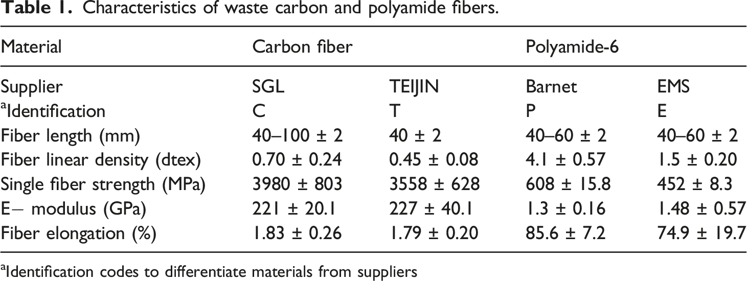
aIdentification codes to differentiate materials from suppliers
Tape manufacturing technology comprising fiber preparation, modified carding, drawing, and tape forming process was used to develop unidirectional tapes, as shown in the Figure 3. For this purpose, different mixing combination based on lengths of carbon fibers, polyamide fibers and fiber volume content were prepared during fiber preparation stage. In this research, each material combination is presented in the format of C40P40V45 or T40E40V45. Here, C40, T40 presents 40 mm SGL (C) and Teijin (T) carbon fiber; P40, E40 denotes 40 mm Barnet (P) and EMS (E) polyamide fibers and V45 express the 45% fiber volume content. Production of unidirectional tape structure.
Multiple mixing combinations were processed on a special DILO carding machine with optimum parameters. In this study, carding machine was adjusted to produce 2.40 ktex hybrid card sliver. Later on, six hybrid card slivers were doubled on a modified Rieter RSB D 40 draw frame with optimum auto leveling and drafting parameters and drawn sliver of 2.8 ktex was produced with a delivery rate of 50 m/min. In the end, eight ends of hybrid drawn sliver were fed on a prototype tape forming machine and unidirectional tapes of 100 g/m2 were developed at a rate of 10 m/min.
Fabrication of UD thermoplastic composites
In order to develop a unidirectional high performance thermoplastic composite, multiple layers of unidirectional tapes were stacked in [0]s direction and consolidation was carried out by utilizing a laboratory scale press machine (P 300 PV from Dr Collin GmbH, Germany). Figure 4(a) to (d) shows the unidirectional tape, tape stacking, consolidation cycle, and consolidated thermoplastic composite. Development of unidirectional thermoplastic composites (a) unidirectional tape, (b) tape stacking, (c) consolidation cycle, and (d) unidirectional composite.
Characterization techniques
The fiber orientation and fiber length in hybrid card slivers, drawn slivers, and unidirectional tapes (without thermal fixation) were measured by Lindsley method and Image analysis method.38,40,41 In order to quantify the damage, combed fibers eliminated during the beard preparation process were further used to measure short fiber content in hybrid slivers. The uniformity in fibrous structure, for example, sliver and tape was measured by using cut-and-weight method and presented in terms of coefficient of variation of irregularity (CV%). 42
The tensile tests of the thermally stable unidirectional tapes were carried out on Zwick type Z 100 (Zwick GmbH and Co., Germany) testing machine. For this purpose, tape of 150 mm × 110 mm size was subjected to tensile testing at a rate of 50 mm/min. The gauge length employed during the tensile test was 100 mm. The tensile properties of high performance composites were carried out by DIN EN ISO 527–5 test method. For this purpose, specimens of 250 mm × 15 mm × 1 mm (l × w × h) were utilized. The fiber volume content and amount of void content were assessed according to ASTM D2734-09 test methods.
The cross section of the hybrid slivers, unidirectional tapes and composites was assessed by using an optical microscope Axio Imager M1m from Carl Zeiss, Germany. To evaluate the fracture zone of composite, the specimen was investigated by using Quanta scanning electron microscopy from Thermo Fisher Scientific Inc., USA.
Results and discussion
Fiber length
The fiber length has a decisive influence on the properties of fiber structures and composites based on them. Therefore, the shortening of the mean fiber length during each step of the tape manufacturing was investigated. In this paper, length of waste carbon fibers was measured after each process step during tape manufacturing. Figure 5(a) represents the mean fiber length of waste carbon fibers after carding, drawing and tape forming processes. The results revealed that mean fiber length of waste carbon fibers decreases from carding to drawing process while the tape forming process hardly causes any fiber damage. The damage of carbon fibers in carding process is considerably higher than during drawing and tape forming processes. This finding is correlated to the carding mechanism that performs point-of-tooth to point-of-tooth action between finisher cylinder and worker, finisher cylinder and doffer. Besides this, back-of-tooth action between finisher cylinder and stripper also perform shearing and striping action. Influence of the steps of the process chain on mean length of carbon fibers (a) C40-100 P40-60V45 (b) C80 P60V45-65.
The carding and shearing actions are the root cause of fiber damage. It can be seen from Figure 5(a) that carbon fibers with a length of 80–100 mm are more severe damaged during carding process compared to carbon fibers with a length of 40–60 mm. This can be attributed to the buckling coefficient of fibers that defines the bending tendency of fibers. 43 The buckling coefficient strongly depends on the fiber properties, for example, length, strength, modulus, and fineness. Keeping a constant fiber modulus, fineness and strength, carbon fibers with a length of 100 mm have 96 times higher buckling coefficient compared to carbon fibers with a length of 40–60 mm. It shows that longer fibers have a much higher tendency of entanglement in carding process. Therefore, carbon fibers with a length of 80–100 mm bend more frequently in the carding process that intensify the fiber damage. It can be concluded from the results that carbon fibers longer than 60 mm are susceptible to higher damage in the carding process.
Figure 5(b) highlights the influence of fiber volume content on carbon fiber length. The results show that the mean fiber length decreases slightly with the increasing proportion of CF content. It can be correlated with the inter-fiber friction among the carbon and polyamide fibers that determines the interactive behavior. 44 In case of higher fiber volume content, inter-fiber friction has decreased due to crimp less surface of carbon fibers. As a result, reduction in interactive forces causes random fiber movement during the carding process. This random fiber movement enhances contact with metallic wires during carding and intensifies fiber damage in hybrid slivers.
Short fibers play a significant role in the quality of fibrous structures and they affect the mechanical behavior of conventional fibrous structures, for example, yarn and fabric. Therefore, the determination of short fiber content was additionally assessed. Figure 6(a) represents the amount of short fiber content (less than 12 mm fiber length) in hybrid drawn slivers. It is clearly seen from Figure 6(a) that hybrid drawn sliver composed of carbon fibers with a length of 80–100 mm contain considerably higher amount of short fibers compared to drawn sliver composed of carbon fibers with a length of 40–60 mm. This can also be attributed to the buckling coefficient of fibers. Further analysis presented in Figure 6(b) show that the amount of short fibers is also affected by the composition of the hybrid sliver. The higher content of carbon fibers enhances fiber degradation in hybrid slivers. It can also be correlated with inter-fiber friction that affects the interactive forces and enhances the fiber damage in hybrid slivers. Short fiber content in hybrid drawn sliver (a) C40-100 P40-60V45 (b) C80 P60V45-65.
Fiber orientation
The fiber orientation also plays an important role in mechanical properties of composites. Therefore, hybrid materials processed on carding, drawing and tape forming processes were subjected to Lindsley method to measure the orientation index in card and drawn slivers. In order to measure orientation index in tape, hybrid fibrous assembly was collected without thermal fixation process. Figure 7(a) and (b) shows the fiber orientation index after carding, drawing and tape forming processes. Fiber orientation index refers to the amount of longer fibers (>12 mm) aligned in machine direction. This quantity based on fibers weight was measured in terms of index rather than angle. Results reveal that there is a significant increase in orientation index after carding and drawing processes. The reason lies in the optimum carding and drawing parameters that yield hybrid drawn sliver with fiber orientation index up to 92%. Results also shows that tape forming process transforms orientated fibrous assemblies into tape structures without distortion. Subsequently, such fiber orientation is embedded in the composite through consolidation. Figure 7(b) presents that fiber orientation index is significantly affected by composition of the sliver. Tapes with 45% fiber volume content possess slightly higher orientation index compared to tapes with 65% fiber volume content. This can be attributed to the lower inter-fiber friction that creates processing difficulties in the carding and drafting processes. Influence of the steps of the process chain on fiber orientation (a) C40-100 P40-60V45 (b) C80 P60V45-65.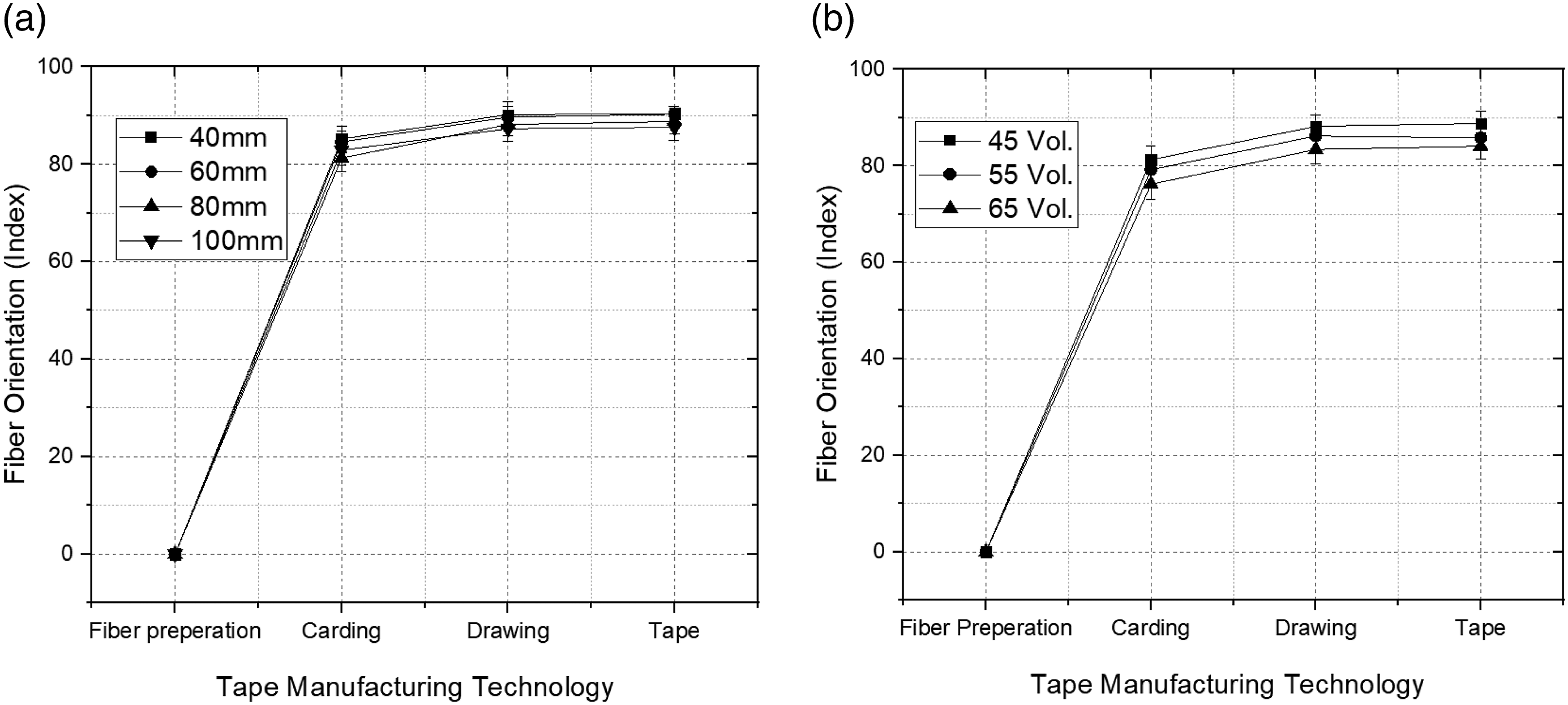
Uniformity of fibrous structure
Uniformity of fibrous structure ensures the reproducibility of the tape structure. Therefore, uniformity of different fibrous structures including, card slivers, drawn slivers, and aerial density of tapes was measured in terms of coefficient of variation (CV-%). Figure 8 shows a dramatic decline in the sliver variation after drawing process. It can be associated with the doubling and auto leveling operations of draw frame.39,43 The results also reveal that hybrid materials (slivers and tapes) composed of carbon fiber with a length of 80–100 mm have higher mass variation per unit length as compared to hybrid material containing carbon fiber with a length of 40–60 mm. This can be correlated to the amount of short fiber present in the hybrid sliver. In drafting zones of drawing and tape forming processes, roller gauges are adjusted according to highest fiber length. Following short fibers behave like floating fibers in drafting operation and generate drafting waves in a drafted fibrous assembly. As a result, a higher initial fiber length of carbon fibers leads to a higher mass irregularity in hybrid sliver. It is because processing of longer fibers leads to higher fiber damage and subsequent higher short fiber content. A similar trend in mass irregularity is also seen in tape structures. Influence of the steps of the process chain on uniformity (C40-100 P60V45).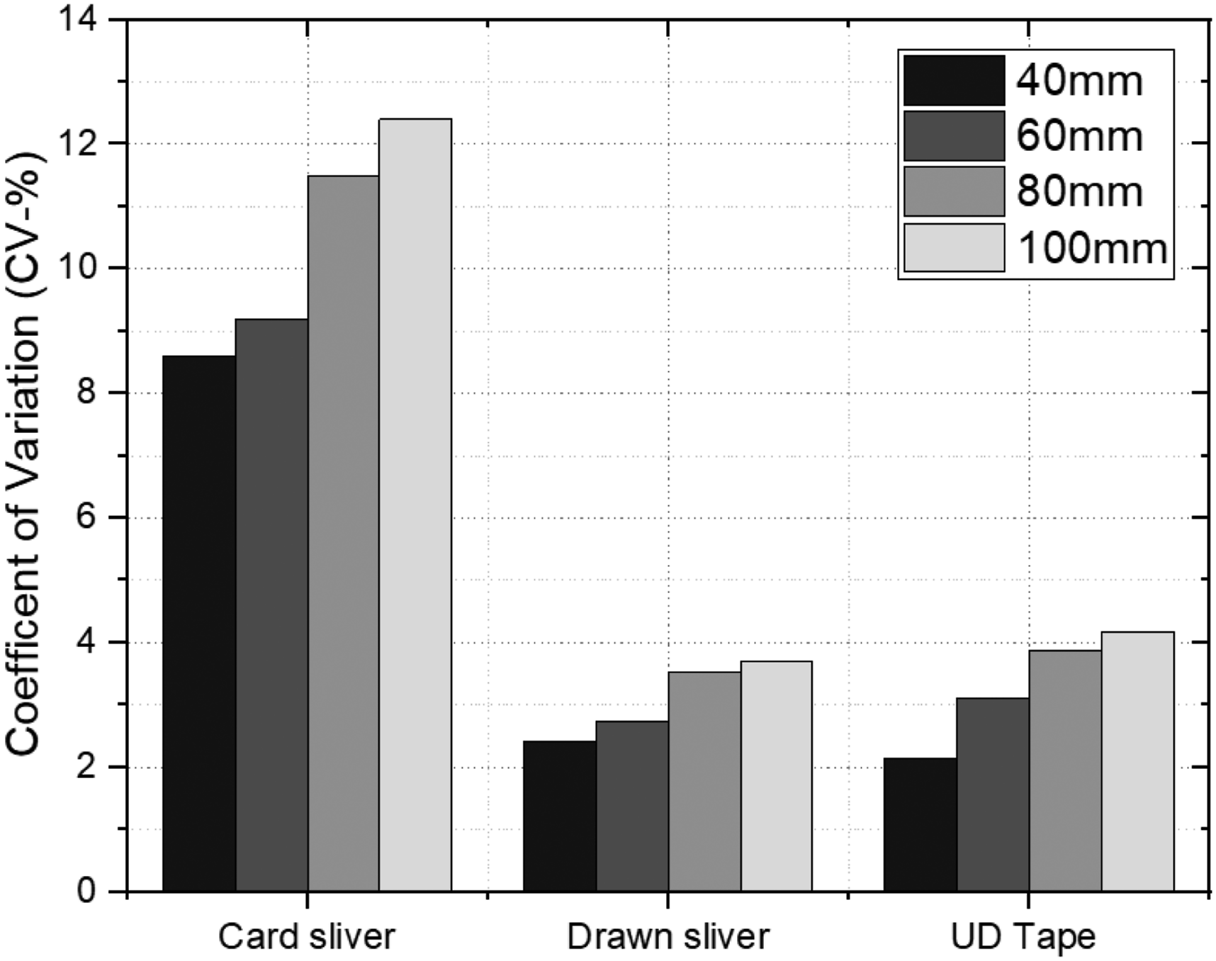
Mechanical properties of unidirectional tapes
Thermal fixation of the tapes takes place by melting polyamide fibers in the hybrid fibrous assembly and impart mechanical stability to the tapes. The mechanical stability of tapes depends on the intensity of infrared radiations and production speed. Figure 9 represents the tensile properties of the stabilized unidirectional tapes. It shows that the intensity of the thermal fixation, length of carbon fibers, and fiber volume content affect the maximum tensile force. The tensile force of the UD tapes rises from 500 to 1500 Newton with increasing IR intensity from 15% to 30% as shown in the Figure 9(a). The reason is a more intense melting of the polyamide fibers in the tapes that creates a more intense bonded structure. Tensile force of unidirectional tapes (a) C80 P60V45 (b) C40-100 P40-60V45 with 15% heating intensity (c) C80 P60V45-65 at 15% heating intensity.
The influence of carbon fiber length on the tensile properties is also shown in the Figure 9(b). It is obvious from Figure 9(b) that tensile force of tape decreases from 800 to 580 Newton at 15% heating intensity with increasing the length of carbon fiber. It can be correlated with the mass irregularity and short fiber content in the fibrous structure that depend on the length of carbon fiber. Hybrid sliver composed of carbon fiber with a length of 80–100 mm has higher mass irregularity and short fiber content compared to hybrid sliver made from carbon fiber with a length of 40–60 mm. Therefore, such factors lead to uneven thermal fixation and cause a decline in tape strength.
With increasing fiber volume content, a decreasing trend in tensile force of the tape is observed, as shown in Figure 9(c). This can also be associated with the inter-fiber friction, short fiber content and mass variation in the hybrid sliver. When fiber volume content in hybrid sliver increases from 45 to 65%, friction decreases among the carbon fibers. This lack of inter-fiber friction creates processing difficulties that affect the structure integrity and mass variation of hybrid sliver. In addition to this, short fiber content increases with higher carbon fiber content and leads to higher mass variation in the tape structure. Consequently, higher mass variation delivers non-uniform thermal fixation in tape structure that affect the tape strength.
Mechanical properties of the composites
Influence of thermal fixation and consolidation pressure
Figure 10(a) represents the influence of thermal fixation and consolidation pressure on the mechanical properties of the composites. The results reveal that infrared intensity under constant consolidation pressure has a significant influence on the composite tensile properties. The composite tensile strength decreases from 850 MPa to 620 MPa when infrared intensity increases from 20 to 30%. It can be correlated with the crystallinity in polyamide fibers.
45
In the tape structure, a higher thermal intensity affects the crystalline region of polyamide fibers that diminish the tensile strength and modulus of the matrix. Subsequently, further consolidation process incorporates this effect into composites. As a result, tensile properties of composites, including strength and modulus, decreased down to 620 MPa and 70 GPa, respectively. Composite properties (a) tensile properties of C80P60V
50
at various heating intensity (b) tensile properties of C80P60V
50
at various consolidation pressure.
Figure 10(b) shows that tensile modulus of the composite is significantly affected by consolidation pressure. Increasing consolidation pressure from 3 to 7 MPa has changed composite modulus from 62 to 86 GPa. As the composite structure is fabricated by stacking of multiple layers of the tapes; therefore, higher pressure during consolidation enforces better cohesion among the layers and yields to composites with higher tensile modulus. In contrast, 7 MPa consolidation pressure is unsuitable regarding composite strength. The optimum consolidation pressure that deliver highest composite strength is 5 MPa. It can be associated with the breakage of fibers under high consolidation pressure. This investigation also concluded that optimum parameters that determine composite strength and modulus are different with each other.
Influence of fiber volume content
Figure 11(a) presents the relationship between tensile properties and fiber volume content in composites. The value of composite modulus increases from 80 GPa to 91 GPa when fiber volume content increases from 45–65% as the modulus increases with the increase of fiber content in composite.
46
Following this logic, the tensile strength of composite manufactured from tapes with carbon fiber volume content of 55–65% was expected to be higher than that of 45%. However, the results reveal that composite strength decreases with increased fiber volume content. The maximum composite strength is achieved at 45–50% fiber volume content. Further increase in the fiber volume content leads to a decrease in tensile strength. It can be associated with multiple structure parameters, such as fiber length, short fiber content, fiber orientation, and mass variation in the tape structure. It is already mentioned that unidirectional tapes fabricated with 55–65% fiber volume content have higher fiber damage, high short fiber content, lower fiber orientation and poor uniformity as compared with 45–50% fiber volume content in tapes. In case of 55–65% fiber volume content, void content remarkably increases in the composite structure as shown in the Figure 11(b) because of non-uniform distribution of matrix and reduces the tensile strength. Composite properties; C60P60V
45-65
(a) tensile properties (b) void content.
Influence of carbon fiber length
Figure 12 shows the tensile properties of composites over the length of carbon fiber. The composite properties are decreases with increasing length of carbon fiber. This can be associated with structural parameters such as fiber damage, fiber orientation and higher mass variation in tapes. In case of 40–60 mm, it is reported earlier that hybrid fibrous structure (slivers and tapes) contains negligible short fiber content. In addition to this, the value of orientation index and uniformity in hybrid fibrous structure is also higher. Therefore, composites developed with 40–60 mm carbon fibers reach up to 1000 MPa strength. Composite tensile properties verses carbon fiber length (C40-100P40-60V
45
).
Besides this, hybrid structures developed from carbon fibers with a length of 80–100 mm show an increasing trend in short fiber content. These short fiber content behave like floating fibers in the further drafting operations and originate drafting waves that enhance mass irregularity in hybrid fibrous structure. 47 In addition to this, orientation of such short fibers is difficult to control in the drafting operations. Consequently, poorly oriented short fibers do not contribute to the composite strength and this causes a significant reduction in the composite strength.
Influence of polyamide fineness
In order to study the influence of polyamide fineness on composite properties, polyamide fibers with 1.5 dtex and 4.1 dtex fineness were used to develop unidirectional tapes. Later on, these tapes were used to produce thermoplastic composite through consolidation. Figure 13 represents the influence of polyamide fineness on the mechanical properties of the composites. It is clearly seen from the Figure 13 that composite developed from finer polyamide (1.5 dtex) have higher tensile strength compared to composite developed from 4.1 dtex polyamide. It can be correlated with the number of fibers present per unit cross section of the hybrid sliver. Polyamide fiber with lower fiber diameter provides homogeneous matrix distribution in the sliver cross section. As a result, homogeneous polyamide distribution improves the processing of hybrid material in carding and drawing and minimize the fiber damage. Furthermore, a homogeneous fiber distribution ensures relatively better bonding properties in composites. As a result, composite strength improves and strength of C40E40V45 composite reached up to 1150 MPa. Composite tensile properties versus Polyamide fineness (C40-60E40-60V45, C40-60P40-60V45).
Influence of fineness of carbon fiber
In order to investigate the influence of the carbon fiber fineness on the composite properties, unidirectional composites with different carbon fineness (0.45 and 0.7 dtex) were developed by using novel tape manufacturing technology with optimum tape parameters. Results presented in the Figure 14 reveal that composites developed with finer carbon and polyamide fibers comprise substantially higher tensile strength. The tensile strength of the thermoplastic composite has reached up to 1370 ± 22 MPa. The reason lies in the fact that finer carbon fibers (0.45 dtex) have a higher surface area to volume as compared to carbon fiber with 0.7 dtex fineness. Therefore, carbon fiber with lower fineness has improved bonding properties. As a rule, composites manufactured from finer carbon and finer polyamide fibers lead to higher tensile strength because of better processing behavior and therefore better fiber and tape structures. Composite tensile properties (T40-60E40-60V45, C40-60E40-60V45).
In order to compare the tensile properties with reference composite, similar continuous carbon fibers tows and polyamide fibers were utilized to develop unidirectional carbon fiber reinforced plastics. The result shows that tensile strength of the continuous carbon fiber reinforced thermoplastics are 1480 ± 130 MPa. The comparison shows that unidirectional tapes with optimum structural and material combinations develop unidirectional fiber reinforced plastics with 93% resource efficiency. These results provide a major breakthrough towards the reutilization of waste carbon fiber into high performance applications.
Current investigations on novel tape manufacturing technology disclose that optimum combination of parameter for tape production leads to composites with outstanding mechanical properties. This can be associated with relatively better bonding between matrix and reinforcement. In order to investigate this, microscopic images of this hybrid sliver, tape and composite structures are presented in the Figure 15(a)–(c). The microscopic images show that optimum combination deliver uniform and homogeneous fiber distribution in hybrid sliver, which provides outstanding bonding properties in tape and composite structures. The microscopy images of the fracture zone shown in the Figure 15(d) and (e) confirm that majority of the carbon fiber are well oriented in the composite structure. These microscopic images also show that majority of the carbon fibers are broken in the composite rather than showing fiber pull out behavior. Microscopy image of T40E40V45 material (a) hybrid sliver (b) thermally stable tape (c) composite 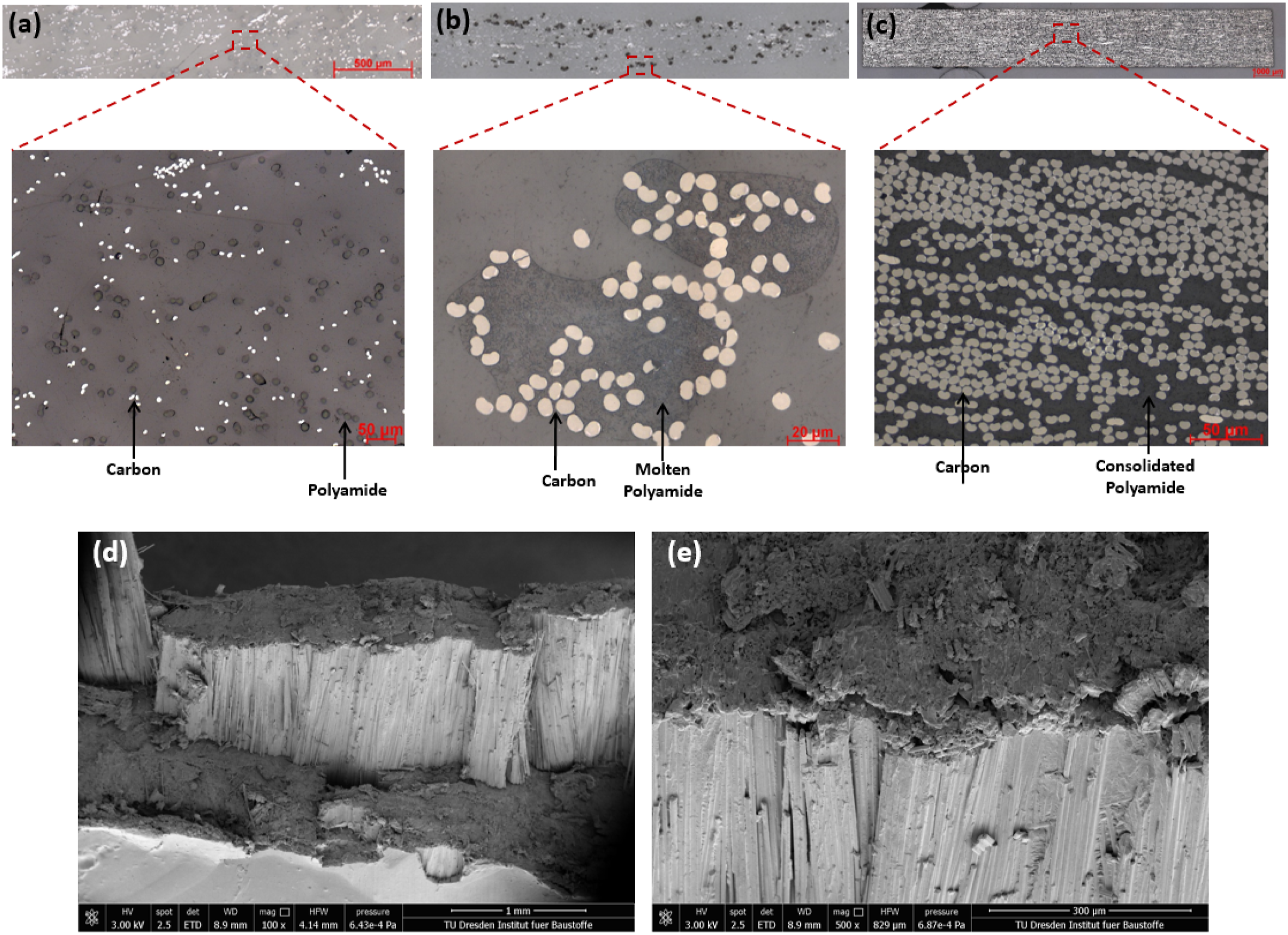
Conclusion
This paper introduces an innovative tape manufacturing technology, comprises of fiber preparation, carding, drawing and tape forming processes, to develop unidirectional tape structure consisting of waste carbon and polyamide fibers. Results show that novel tape manufacturing technology develop unidirectional tape structure with 92% fiber orientation. Investigations also shows that content of short carbon fibers affect the fiber length distribution, orientation and uniformity in unidirectional tapes and composites. Analysis shows that unidirectional tapes structure with lower short carbon fibers content deliver composites with outstanding tensile properties. This study also investigates the influence of different material combinations such as fiber volume content, fiber length and fineness of carbon and polyamide fibers on the tensile properties of the composites. The results reveal that combination contain similar fiber lengths (carbon and polyamide), lower fineness and 45–50% fiber volume content develops composite with tensile strength up to 1370 ± 27 MPa. The results also disclose that high performance composites developed through unidirectional tape structures can be used for load bearing structural applications in automotive and aviation.
Footnotes
Declaration of conflicting interests
The authors declared no potential conflicts of interest with respect to the research, authorship, and/or publication of this article.
Funding
The author(s) disclosed receipt of the following financial support for the research, authorship, and/or publication of this article: This article presents parts of the results from the research program of the German Federal Environmental Foundation [AZ-33809/01] and Industrial Collaborative Research [IGF-20515 BR] of the Forschungsvereinigung Forschungskuratorium Textil e.V. funded through the AiF within the program for supporting the „Industriellen Gemeinschaftsforschung (IGF)“ from funds of the Federal Ministry of Economic Affairs and Energy (BMWi) by a resolution of the German Bundestag.