
Abstract
The auto-leveling system of a modern draw frame is widely used for conventional fibers to develop homogeneous, uniform, and defect free drawn slivers. This auto-leveling system also improves the quality of tapes and hybrid yarn structures by eliminating mass irregularities in hybrid sliver. However, the existing auto-leveling system exerts very high loads on feedstock, thus diminishing the quality of waste carbon in the delivered sliver. The aim of the present study was to process hybrid sliver based on waste carbon and polyamide fibers on a modern draw frame and modify the auto-leveling system to enable the damage-free processing of carbon fiber. For this purpose, hybrid card slivers were processed on an industrial draw frame with auto-leveling system. The different auto-leveling parameters, e.g., scan roller width and scan roller load, were modified and optimized for the uniform and damage-free processing of hybrid sliver. Results revealed that the scan roller load has a significant influence on the quality of waste carbon fiber in hybrid sliver. A uniform hybrid sliver ensures the reproducibility of unidirectional tapes and hybrid yarn at industrial scale, while simultaneously maintaining the quality of recycled carbon fiber-reinforced thermoplastics.
Introduction
The rapidly growing demand for carbon fiber-reinforced plastics in high-tech industries, such as aerospace, defense, automotive, and wind turbine engineering, resulted in a high amount of waste carbon fiber in the form of dry waste (e.g., production off cuts), wet waste (resin impregnated waste, e.g., out-of-date prepreg rolls), and end-of-life waste [1–3]. Dry and wet wastes, originated from the composite industry, account for 30%–40% of the total manufacturing waste of carbon fiber-reinforced plastics [4]. Recently, developing countries including the USA, UK, and Germany have generated individually 3 kilotons of dry and wet waste carbon fiber annually [5]. Throughout the next decade, high-tech industries are expected to produce an enormous amount of additional carbon fiber waste in the form of retired or end-of-life carbon fiber-reinforced plastics components [6]. Therefore, the processing of waste carbon fiber and its integration into fiber-reinforced thermoplastics has significantly gained in importance within the past 10 years [7].
Initially, waste carbon fiber obtained from manufacturing waste was processed by injection molding to develop recycled carbon fiber-reinforced thermoplastic composites. Injection molding leads to a homogeneous mixture of reinforcement and polymer and is capable of producing thermoplastic composites in reproducible quality. However, this processing technology yields composites with random fiber distribution and low-fiber volume content. In addition, only short or milled carbon fibers can be processed through injection molding. Therefore, thermoplastic composite developed from injection molding has limited mechanical properties [7–9]. In order to improve the mechanical properties of recycled carbon fiber-reinforced thermoplastics, several attempts were carried out in the last decade to processes waste carbon fiber on different textile machines [10–12]. The resulting fibrous structures based on nonwovens [13], tapes [14,15], and hybrid yarns [16–18] are further utilized for the fabrication of recycled carbon fiber-reinforced thermoplastic composites.
In order to process brittle and conductive waste carbon fibers on textile machines, several modifications and developments were required to enable uniform and damage-free processing. For instance, Akonda et al. performed pioneer work on textile machines to process waste carbon and polypropylene fiber and develop hybrid yarn structures by wrap spinning [19]. Hengstermann et al. also reported on necessary modifications to a laboratory scale-carding machine. Furthermore, a drafting unit of a drawing machine was also adjusted to make it suitable for waste carbon and polyamide fibers. Finally, a hybrid yarn structure was developed on a flyer machine [11]. Wölling et al. employed these modifications on an industrial dry laid process to produce nonwoven structures for recycled carbon fiber-reinforced plastics [20]. Hasan et al. also realized these modifications and optimized the different parameters of friction spinning to develop a hybrid yarn structure [17]. Khurshid et al. reported on the optimization of a semi industrial carding machine to process waste carbon and thermoplastic fibers and develop unidirectional tape structures for recycled carbon fiber-reinforced plastics [21,22]. These studies show that unidirectional tapes and hybrid yarn structures have a great potential to develop fiber-reinforced plastics with promising mechanical properties. Therefore, the development of unidirectional tapes and hybrid yarn by means of textile machinery has been gaining attention in academia and industry [23–26]. However, the problem associated with these structures involves their lacking reproducibility at industrial scale.
In order to achieve unidirectional tapes and hybrid yarn with a reproducible quality, irregularities in mass per unit length must be eliminated. It is fully established that an auto-leveling system significantly improves the quality of drawn sliver by eliminating mass irregularities [27–29]. Therefore, hybrid sliver composed of waste carbon and polyamide fibers must be processed with an auto-leveling system to achieve a reproducible quality. However, current auto-leveling system is designed for conventional fibers (natural or synthetic). It is unsuitable for waste carbon fibers because scanning gear of the existing auto-leveling system exerts 800 newton loads on slivers. Consequently, brittle carbon fibers are damaged in the hybrid sliver, causing a significant increase in broken fiber content. Recently, it is established that fiber length is an important factor that determines the performance of recycled carbon fiber-reinforced thermoplastics composites [16,30]. Therefore, there is a strong need to modify the auto-leveling system for the uniform and damage-free processing of hybrid sliver composed of waste carbon fiber.
The main objective of this study is to modify the auto-leveling system of a modern draw frame to develop a uniform hybrid sliver with minimum fiber damage. For this purpose, the auto-leveling system of a modern Rieter RSB D-40 draw frame was modified for the uniform and damage-free processing of waste carbon fiber. Finally, the influence of different leveling parameters on the quality of hybrid drawn sliver and waste carbon fiber were also studied. The obtained research results suggested necessary modifications to the auto-leveling system of a Rieter RSB D-40 draw frame for the processing of waste carbon fiber. As a result of the adjustments made, a uniform hybrid sliver can be used for the production of unidirectional tapes and hybrid yarn.
Materials and methods
Materials
The hybrid card sliver employed in this study was composed of 50% (vol.) waste carbon fiber and 50% (vol.) polyamide fibers. The waste carbon fiber used in this study was purchased from SGL Group, Germany. This type of waste carbon fiber was obtained from leftover tows. The Barnet Europe, Germany, supplied the polyamide fiber (PA-6). The fiber characteristics of both fibers are given in Table 1.
Properties of carbon and polyamide fibers.

A semi-industrial spinning plant was utilized for the production of hybrid card sliver. The DILO Group, Germany, designed this pilot plant for the processing of waste carbon. It consists of an opener, a chute feeder, and a double cylinder-card machine. The fiber opener reduces the size of fiber bundles and transfers to the chute feeder by the help of an air current mechanism. Finally, a double cylinder-carding machine was employed to convert blended fibers into hybrid sliver. This detail of the setup was reported in Khurshid et al. [21]. The quality parameters of hybrid card sliver are given in Table 2.
Quality of hybrid card sliver.

SD: standard deviation.
Modification to the auto-leveling system
A Rieter RSB D-40 draw frame was employed for the processing of hybrid card sliver composed of waste carbon and polyamide fibers. These hybrid slivers were processed on a modern draw frame with auto leveling system. The draw frame was set to deliver a drawn sliver of 3.35 ktex. For this purpose, 20 ktex hybrid card slivers were fed as feedstock and drawn sliver were drafted with a ratio of 5.98. The roller distance of the breaker and main finisher zone were to 70 and 65 mm, respectively, because the carbon fiber length in card sliver is 62 ± 2.2 mm. The detail of technological parameters employed for the processing of hybrid sliver is given in Table 3. The principle diagram of the auto-leveling system of Rieter RSB D-40 draw frame and processing of hybrid sliver composed of waste carbon and polyamide fibers are presented in Figure 1(a) to (d).
Technological parameters of hybrid drawn sliver.


Rieter RSB D-40 draw frame (a) principle of auto leveling [35], (b) sliver feeding, (c) scanning segment and (d) drafting of hybrid sliver.
Figure 1(a) represents the auto-leveling system of a Rieter RSB D-40 draw frame. It is clearly seen from the schematic diagram that the auto-leveling system consists of a pair of scanning discs or rollers, a digital signal processor, and a servo drive. The scanning disc and its associated pressure disc scan the mass variation of input slivers. The mass variation in feedstock is converted into an electrical signal, which is processed by a digital signal processor. Based on mass variation, the digital signal processor calculates a reference speed of a servo drive. The servo drive is connected to a planetary gearbox and changes the speed of the in-feed section of the draw frame (e.g., creel, scanning rollers, in-feed, and middle drafting rollers) to eliminate mass irregularities in the delivered sliver.
Investigations on scan roller width
The scanning segment of the auto-leveling system consists of a pair of discs termed as scanning rollers. These scanning rollers apply a load of approximately 800 N on input slivers, which leads to a surface pressure of 40 N/mm2. For the calculation of surface pressure, it is estimated that a force of 800 N is effective on a sliver length of 4 mm. The resulting surface pressure depends on the width of scanning rollers. Scanning rollers are available in different widths, and their selection depends on material type and feedstock. A suitable guideline regarding the width of scanning rollers for conventional materials is given in the technical manual of the Rieter RSB D-40 draw frame. The width of scanning discs provides sufficient space for input slivers during the scanning process. The larger width of scanning rollers provides more space for feedstock. Therefore, larger scanning discs exert a lower surface pressure on feedstock as presented in Figure 2. Therefore, different widths of scanning rollers (5.5, 7.0, 9.0, and 11 mm) affecting the surface pressure were investigated in the first part of this study. Subsequently, a calibration process and sliver protocol tests were exercised after changing the scan roller width. Finally, the influence of the scanning roller width on the quality of waste carbon fiber and drawn sliver was measured.

Surface pressure and load of different scan rollers.
Investigations on scan roller load
Scanning roller load is one of the most critical parameters. For conventional applications, the load on input slivers during scanning is kept constant at 800 N. This is the standard load for the processing of conventional fibers. In contrast, it is unsuitable for the processing of waste carbon fibers due to their brittle behavior. Thus, carbon fibers are damaged during scanning and the short fiber content is significantly increased in the delivered sliver. In order to overcome this limitation, the auto-leveling system of a Rieter RSB D-40 draw frame was modified in collaboration with Rieter Ingolstadt GmbH, Germany. Subsequently, hybrid slivers were processed on a drawing machine and the influence of scan roller load on the quality of drawn sliver and waste carbon fiber was measured and analyzed.
The calibration process was carried out by using 3, 4, 5, and 6 mm gauges and their corresponding voltages (mV), which represent the measured distance of the eddy current sensor in the scanning gear, were measured and compared with standard given values (as shown in the machine display 82.2). Then, a sliver protocol test was performed to determine the suitable value of leveling intensity. The step-by-step calibration process of scanning rollers and the procedure of the sliver protocol test are given in Ref. [36].
Testing of hybrid drawn sliver
The testing of hybrid drawn sliver was impossible on standard techniques, e.g., Uster auto sorter, Uster evenness tester (UT-5), Uster AFIS Pro, due to the conductive nature of carbon fiber and origination of carbon dust. Therefore, the quality of waste carbon fiber and hybrid drawn sliver were examined by means of novel testing techniques.
Measurement of sliver linear density
The linear density of hybrid drawn sliver was measured by the weight method [31]. In this method, a specific length of drawn sliver was weighted and the following equation was used to calculate the sliver linear density
Measurement of sliver irregularity
The irregularity in mass per unit length of hybrid drawn sliver was measured by using the cut and weight method [31]. Hence, 25 m of consecutive drawn sliver length was cut into pieces of 1 m. Next, each sliver was weighted and a variation in mass per unit length is represented by the coefficient of variation (CV %).
Determination of waste carbon fiber quality in drawn sliver
The quality of waste carbon fiber in hybrid sliver was measured by the Image Analysis method as reported in Refs. [21,30,32]. Thus, a sliver of specified weight was clamped side by side in a clamping device as given in Figure 3(c). In a next step, clamped fibers were oriented in the longitudinal direction with combing mechanism. Furthermore, the fiber beard was scanned and scan image was processed by Matlab software. Finally, grayscale densities of different class lengths were used to draw a staple length diagram and the mean fiber length was calculated as represented in Figure 3(d).

Principle of image analysis method (a) clamping device, (b) hybrid sliver, (c) fiber beard, and (d) staple diagram [21].
Results and discussion
Influence of scan roller width on the quality of drawn sliver and waste carbon fiber
The scanning segment is an important part of an auto-leveling system. It consists of a pair of discs. One disc is fixed in the auto leveling system. In contrast, the scanning or pressure disc moves from its mean position termed as 0% scan roller distance with respect to mass variation in the input sliver and maintains a constant surface pressure on the input material. This surface pressure is affected by the width of the scanning roller as described in the previous section. Therefore, scanning rollers with different widths (5.5, 7.0, 9.0, and 11 mm) were varied on the draw frame. The results obtained in terms of the quality of waste carbon fiber and drawn sliver are presented in Table 4. Furthermore, 0% scan roller distance (as shown in the machine display 20.2) was also recorded at the end of every test and is presented in Table 4.
Results of investigations on the influence of scan roller width on hybrid sliver and waste carbon fiber.

SD: standard deviation.
The influence of different scan roller widths on the quality of drawn sliver, waste carbon fiber, and machine parameters (0% scan roller distance) are presented in Table 4. Results suggest that 5.5, 7.0, and 9.0 mm scan rollers yield identical qualities of drawn sliver. The values of sliver irregularity and sliver linear density are in the same range. In contrast, scan roller with a width of 11 mm results in very poor sliver evenness and can be correlated with 0% scan roller distance. The value of 0% scan roller distance indicates the space between scanning rollers without variation in input slivers. The acceptable range of this parameter is between 2.500 and 5.600 mm in order to maintain a sufficient control reserve. Results show that an increased scanning roller width reduces the 0% scan roller distance. In the case of 11 mm, the value of the 0% scan roller distance is below the given technical range, i.e., the scan roller width of 11 mm has reached its technological limits. Consequently, auto-leveling cannot control variations in the delivered sliver. It can be concluded from the results that a 9.0 mm scan roller is suitable for the processing of waste carbon and was therefore identified as recommended parameter.
Table 4 presents the influence of scan roller width on the quality of waste carbon fiber. The results clearly prove that the length of waste carbon fiber is significantly reduced in drawn sliver. The carbon fiber length is slightly increased with a higher scan roller width. This can be correlated with the change in surface pressure, which decreases with an increased scanning roller width. However, fiber damage still exceeds 50% in the drawn sliver. A visual examination of drawn sliver processed with a 9.0 mm scan roller width is given in Figure 4. These images highlight that an enormous amount of short fibers is present in the drawn sliver as processed with auto leveling system. This is due to the high scan roller load that is unsuitable for carbon fiber. Therefore, the load applied by the scan roller was reduced in further investigations.

Visual examination of drawn sliver processed with 9.0 mm scan roller width: (a) drawn sliver and (b) highlighted section of drawn sliver.
Influence of scan roller load on the quality of drawn sliver and waste carbon fiber
The scanning disc is one of the most important segments in auto-leveling as it maintains a constant load input sliver. The pressure of the scanning disc is achieved by a system designed by Rieter in its RSB D-40 drawing machine according to Figure 5. The diagram reveals that the scanning gearbox consists of three main components: pneumatic cylinder, lever, and spring. These components are connected with each other and maintain a constant load on input slivers. The pneumatic cylinder stretches the spring component through the lever and ensures a constant load acting on the scanning disc. In order to reduce the scanning disc pressure, the spring stretch can be adjusted by increasing the rod length of the pneumatic cylinder; alternatively, the current spring component can be replaced with a new spring.
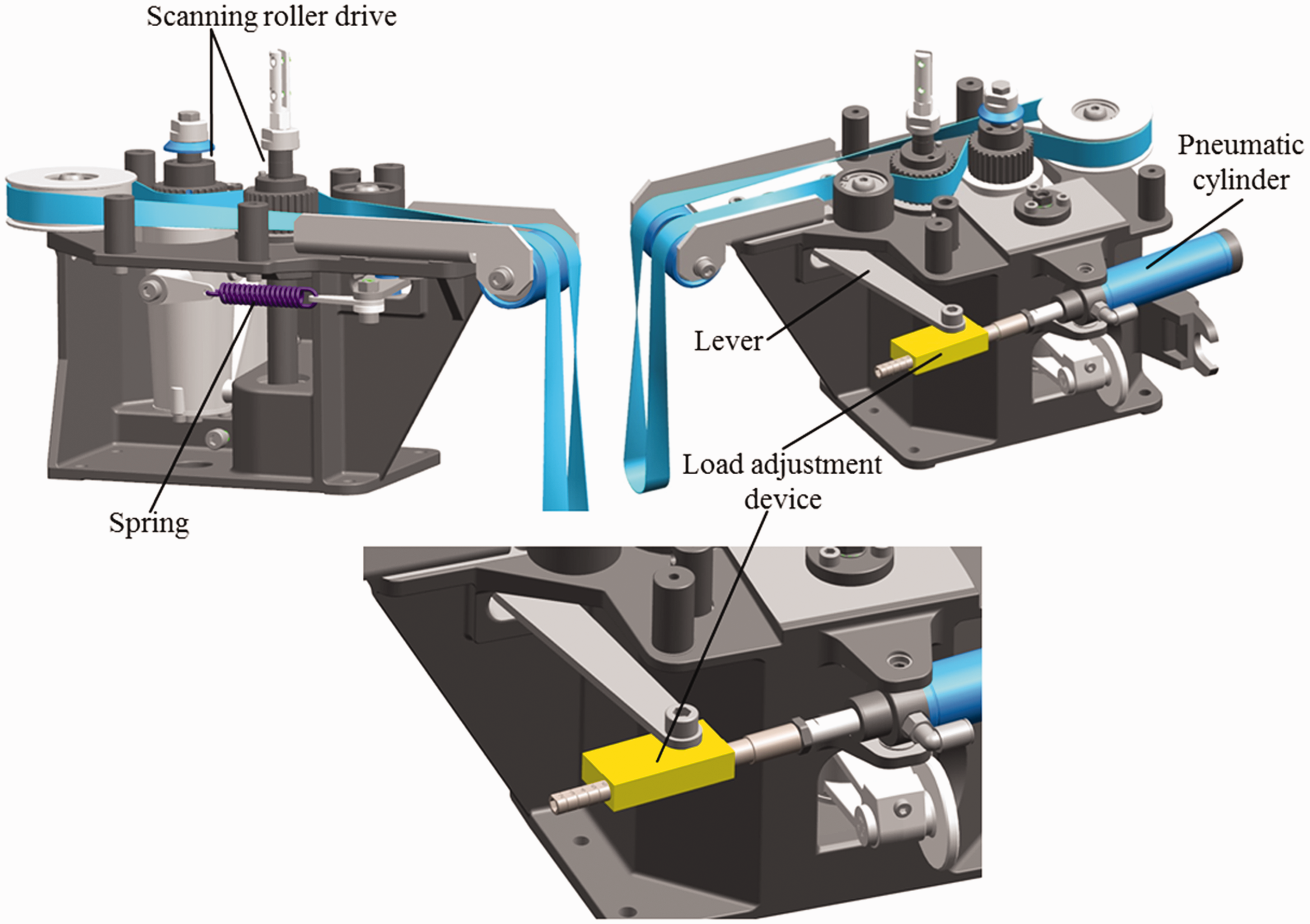
Load adjustment device integrated in scanning gear of Rieter RSB D-40 draw frame.
Therefore, a new load adjustment device designed by Rieter was initially integrated into the auto-levling system of the Rieter RSB D-40 draw frame as shown in Figure 5. This device is coupled between the pneumatic cylinder and a lever end. It provides the flexibility of reducing the load acting on the scanning roller by increasing the rod length of the pneumatic cylinder. A higher rod length leads to decreased stretch on the spring, thus reducing the force on the scanning roller. Furthermore, this device provides six adjustments levels that reduce the load from 800 to 200 N. In this investigation, three scan roller loads of 800, 500, and 200 N were selected. Moreover, hybrid card slivers were processed on a draw frame with auto-leveling system and the influence of scan roller load on the quality of drawn sliver and waste carbon fiber is presented in Table 5.
Results of investigations on the influence of scan roller load on hybrid sliver and waste carbon fiber.
SD: standard deviation.
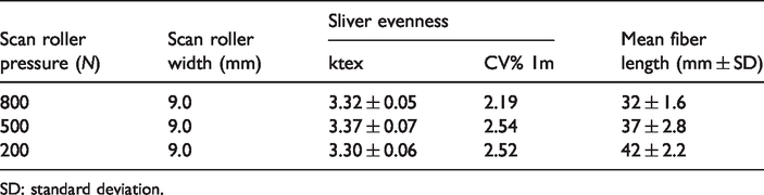
It can be interpreted from the results that a lower load on the scan roller yields the same drawn sliver quality. Results in terms of sliver irregularity and sliver linear density are identical for all levels of scan roller load. The impact of different scan roller loads on the length of waste carbon fiber is also given in Table 5. The results revealed that roller pressure has a significant effect on carbon fiber length. The values of fiber length are increasing with changing loads; a load of 200 N applied onto the scan roller delivers the highest value of fiber length. However, the fiber damage that occurs in the delivered drawn sliver still exceeds 30%. Furthermore, it is concluded from the results that scan roller load has a significant impact on mean carbon fiber length. Therefore, the load of the scan roller was further reduced and the influence of scan roller load on waste carbon fiber was investigated.
In the next phase of this investgation, a new spring with lower stiffness was installed on the machine as shown in Figure 6. The new spring is capable of reducing the load on scan rollers. In combination with the load adjustment device integrated in autoleveling, three scan roller loads were chosen for further investigation. Then, hybrid card slivers were processed on a draw frame with auto leveling system. The results of different scan roller loads affecting the quality of drawn sliver and waste carbon fiber are presented in Table 6.

Spring integrated in auto leveling system of Rieter RSB D-40 draw frame: (a) original spring and (b) new spring.
Results of investigations on the influence of scan roller load on hybrid sliver and waste carbon fiber.

SD: standard deviation.
It can be deduced from the results that the auto-leveling system is working on a 50 N scan roller load and generates drawn sliver in identical quality. The values for sliver irregularity and sliver linear density are also on the same level. It is also assumed that the resulting fiber lengths reached their optimum value. It is concluded from the results that a pressure below 70 N has not significant effect on fiber length. Therefore, 70 N loads are selected as recommended load for the processing of waste carbon fiber. A visual examination of the drawn sliver processed with these recommended settings is provided in Figure 7. The image of a drawn hybrid sliver shows that a hybrid sliver composed of waste carbon fiber is gently processed on a draw frame with auto-leveling system. During experiments, it was observed that the scanning capability of input slivers is limited to 25 ktex after reducing the load on a scan roller with a 9.0-mm width.
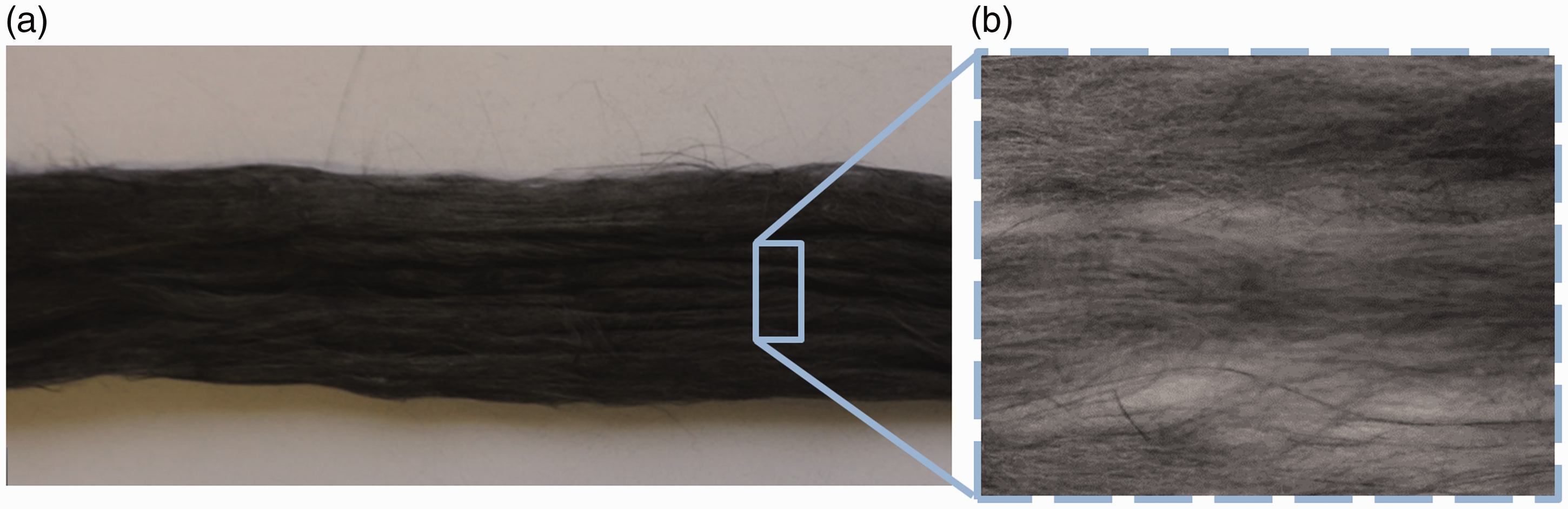
Visual examination of a drawn sliver processed with recommended settings: (a) drawn sliver and (b) highlighted section of drawn sliver.
Conclusion
In this study, an auto-leveling unit of a modern Rieter RSB D-40 draw frame was modified for the uniform and damage free processing of waste carbon fibers. For this purpose, modifications were carried out in collaboration with Rieter Ingolstadt GmbH, Germany. Subsequently, hybrid card slivers were processed on a draw frame with a modified auto-leveling system and effects of these modifications on the quality of waste carbon fiber and drawn sliver were measured and analyzed. The results of this study revealed that modifications to the scanning roller load are one of the most important parameters affecting the quality of waste carbon fiber. Therefore, the load of the scan roller was initially reduced by integrating a load adjustment device. In a next step, the load was further reduced by replacing the existing spring with a new one. The results obtained suggest a recommended load of 70 N, which delivers a hybrid sliver with minimum fiber damage. These investigations provide a solid knowledge base for the development of a reproducible and uniform drawn sliver with minimum fiber damage at industrial scale. Furthermore, the quality of unidirectional tapes and hybrid yarn based on waste carbon fiber are considerably improved.
Footnotes
Declaration of conflicting interests
The author(s) declared no potential conflicts of interest with respect to the research, authorship, and/or publication of this article.
Funding
The author(s) disclosed receipt of the following financial support for the research, authorship, and/or publication of this article: This article presents parts of the results from the research program of the German Federal Environmental Foundation [AZ-33809/01] at the Technical University Dresden.