
Abstract
Thermoplastic sizing agents, which are primarily composed of thermoplastic polymers, are functional coating materials used to improve the surface characteristics of fibers or fabrics. They are frequently employed in aerospace applications and can increase the fatigue resistance of carbon-fiber composite panels. However, carbon fiber (CF) sizing agents present new challenges due to the high molding temperature and inert nature of thermoplastic resins. This study used the thermal imidization technique and polyamide acid (PAA) synthesis to create PI, a carbon fiber sizing agent. Up to 370°C, the PI sizing agent exhibits outstanding thermal stability; at 390°C, it decomposes by just 3.86%. To improve the mechanical and interfacial qualities of CF/PEEK composites, PI was set up as an aqueous solution for carbon fibers and sizing treatments based on the solubility of its ammonium polyamides. According to the mechanical test findings, the B-DCF/PEEK composites’ flexural strength and ILSS were 540.14 MPa and 40.45 MPa, respectively. These values were 69.92% and 76.10% greater than those of the CF/PEEK. Additionally, based on the microscopic morphology of the composites at the fracture, the sizing agent can enhance their interfacial properties. This paper offers technical support for the use of high-performance CF/PEEK composites in high-temperature and high-load industries like aerospace.
Introduction
Materials are the essential foundation for societal advancement. In recent years, carbon fiber reinforced composites have gained extensive application in aerospace, mechanical transportation, and other sectors due to their high strength, high modulus, and low density properties.1–4 In comparison to thermosetting resins, thermoplastic resins offer superior impact resistance, ease of processing, longevity, recyclability, and low absorption qualities, which enable them to retain excellent mechanical capabilities in humid and particular temperature conditions.
Polyether ketone (PEK), polyetherether ketone (PEEK), polyimide (PI), and polyphenylene sulfide (PPS) are examples of thermoplastic resins that are frequently utilized.5–7 With a chemical structure made up of alternating benzene rings, ether bonds, and ketone bonds, polyether ether ketone (PEEK) is a high-performance thermoplastic aromatic polymer that exhibits outstanding heat resistance, thermal stability, and flexibility.8,9 Along with its exceptional mechanical qualities and fatigue performance, PEEK also possesses high strength, chemical resistance, and abrasion resistance. PEEK is a common alternative for the production of composites and is gaining more attention in the research community due to its superior mechanical qualities and stronger thermal resistance compared to other resins like PES and PPS.8–11 The widely recognized carbon fiber reinforced polyether ketone (CF/PEEK) composites are increasingly used in aircraft structural components, such as the flaps of the Airbus A380, which use carbon fiber reinforced thermoplastic composites to reduce weight and improve fuel efficiency by optimizing material properties and design. 12 These composites are used in the aerospace industry, automotive manufacturing, sports equipment, and other fields. The carbon fibers and the PEEK resin have a low interfacial bonding strength because the PEEK molecular chain segments are inert towards the carbon fibers, making it difficult for the two to form a stable chemical bond. 13 The mechanical properties of carbon fiber-reinforced polyether ketone composites are limited by this low interfacial bonding property, particularly concerning interfacial adhesion and shear strength. For the interfacial bond strength, the interfacial layer is crucial in bridging the load transmission between the carbon fibers and the resin matrix.14–16
The surface treatment of carbon fibers is an efficient way to increase the interfacial binding strength between carbon fibers and matrix, and researchers have begun to investigate how to improve the interfacial characteristics of carbon fibers and resins. 17 Gas-phase oxidation, 16 liquid-phase oxidation,17,18 plasma treatment,19–22 electrochemical deposition, 23 surface coating, 24 surface chemical grafting, 25 and sizing 26 are examples of common surface treatment methods. Using a vacuum-assisted resin transfer molding technique, Su et al. 27 examined the impact of plasma treatment on carbon fiber polymers by enhancing the interlaminar shear strength of carbon fiber composites. By applying a coupling agent coating to the surface of carbon fibers (CFs) that have been exposed to oxygen plasma, Zhang et al. 28 showed a notable increase in the material’s mechanical characteristics and structural integrity. The untreated carbon fiber-reinforced composites had a compressive strength of 216.98 MPa and a flexural strength of 54.78 MPa, which was a 250% decrease. Of the two technologies mentioned above, the preparation of plasma-treated carbon fibers is more costly and has more challenges when compared to online CF manufacturing. Contrarily, the coupling agent coating approach is simple to use. 29 However, because most coupling agents are not very resistant to temperature, the aforementioned techniques are ineffective in enhancing the interfacial characteristics between CF and resin. As a result, numerous investigations into the interface between carbon fiber and a resin matrix have been carried out, and several thermoplastic sizing agents have been created. One of the commercially accessible polymers with extremely high heat stability is aromatic polyimide (PI).30–33 It is a fantastic option for covering carbon fibers with high-temperature thermoplastic reinforcements because of its distinctive structure and high level of aromaticity. 34 Using impregnation and high-temperature vapor deposition polymerization (VDP) coating techniques, Naganuma et al. 35 examined the impact of polyimide coatings on the tensile strength of carbon fiber filaments based on high-strength polyacrylonitrile (PAN). Nevertheless, for carbon fibers, this approach is extremely complicated and incompatible with mass production methods. Sizing treatment is a widely used technique for controlling the dimensions and facilitating the thermal imidization of polyamide acid (PAA) in the fabrication of polyimide (PI) coatings. Nonetheless, organic solvents are present in the majority of PAA sizing agents utilized in earlier research. 36 These organic solvents’ fumes pose major health risks to employees, as well as the potential for accidents like explosions. Making an organic, solvent-free sizing agent for carbon fibers is therefore essential. After modifying CF using an organic solvent-free polyamide acid (PAA) aqueous sizing agent, Yuan et al. 37 observed a 47.9% increase in the interfacial shear strength between CF and PES. As a sizing agent for CF, Yuan et al. 38 produced an easily purified aqueous semialiphatic polyimide. By modifying the sizing agent with SA-PI, the interfacial strength increased by 47.9%. The tensile and flexural strength of CF/PEEK composites is further increased by the presence of physical entanglement in the molecular chain, which promotes adhesion due to the mutual solubility of the SA-PI sizing agent and PEEK resin. The two resins may also have a π-π stacking structure. Finding the right sizing agent is crucial. The surface coating approach 6 is now a popular and efficient way to enhance the interfacial bonding between CF and the resin matrix for CF/PEEK composites. It is also simple to industrialize.
This study describes the synthesis of a polyimide solution as a sizing agent, with carbon fiber being scaled using both an aqueous polyamide acid solution and an organic solvent solution. The surface morphology of carbon fibers post-sizing was examined using SEM. The functional groups and chemical bonds of the composites were analyzed using Fourier-transform infrared spectroscopy. The decomposition temperature of the sizing agent was determined using thermogravimetric analysis. The macroscopic interfacial characteristics of CF/PEEK composites were examined through three-point shear beam and bending tests, revealing a significant enhancement in both bending strength and interlaminar shear strength. This suggests that the solvent-free sizing agent employed effectively enhances the interfacial properties of the composites. The research validates that polyimide (PI) sizing agents can markedly enhance the interfacial bonding characteristics of carbon fiber-reinforced high-temperature thermoplastic composites, indicating their potential for industrial use in aerospace and advanced manufacturing.
Experiment
Material
Plain woven carbon fiber (face density of 200 g/m2) and unidirectional fiber, both provided by Shanghai Xinao Composites Technology R&D Centre. PEEK powder provided by Jilin Zhongyan Polymer Material Co. Pyromellitic dianhydride (PMDA>99%) was acquired from Shandong Keyuan Biochemical Co. 4,4′-Diaminodiphenylmethane (MDA >99%) was acquired from Shanghai McLean Biochemistry Science and Technology Co., and N, N-Dimethylacetamide was obtained from Tianjin Damao Chemical Reagent Factory. Sodium hydroxide was acquired from Tianjin Aopusheng Chemical Co. Deionized water was synthesized in the laboratory.
Preparation of PI sizing agent
Synthesis of polyimide
Polyamide acid (PAA) was synthesized as detailed below: Pyromellitic dianhydride (PMDA) was precisely measured with 4,4′-Diaminodiphenylmethane (MDA) at a molar ratio of 1.02:1 and subsequently dissolved in N, N-dimethylacetamide (DMAc) solvent. The heterogeneous solution underwent continuous agitation at ambient temperatures for 10 hours. The ultimate organic solution of polyamide acid (PAA) was created. Figure 1 illustrates a schematic of this synthesis process. Synthesis of semi-aliphatic PI.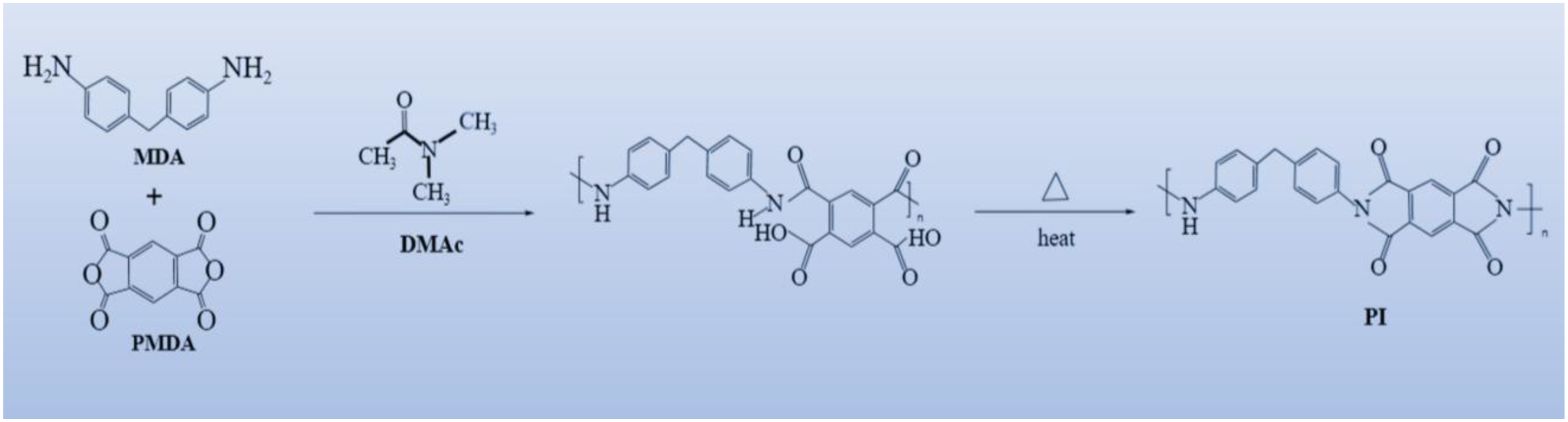
The produced polyamide acid solution is thereafter transferred to a dispensing funnel and added dropwise to deionized water. A white precipitate eventually formed from the fluid throughout this process. The white precipitate is obtained through filtration and subsequently washed multiple times with deionized water to eliminate the remaining organic solvent. The washing procedure persists until the pH of the washing solution attains neutrality (pH = 7) to guarantee the absence of residual contaminants on the precipitate’s surface. Upon completion of the washing, the resultant white precipitate was exposed to a drying procedure in an oven at 85°C until fully dehydrated. The dried precipitate was ultimately pulverized into powder to yield polyamide acid (PAA) powder for the following studies, as illustrated in Figure 2(a). Flow chart of polyimide (PI) sizing agent preparation: (a) Sizing agent preparation step, (b) Carbon fiber sizing step.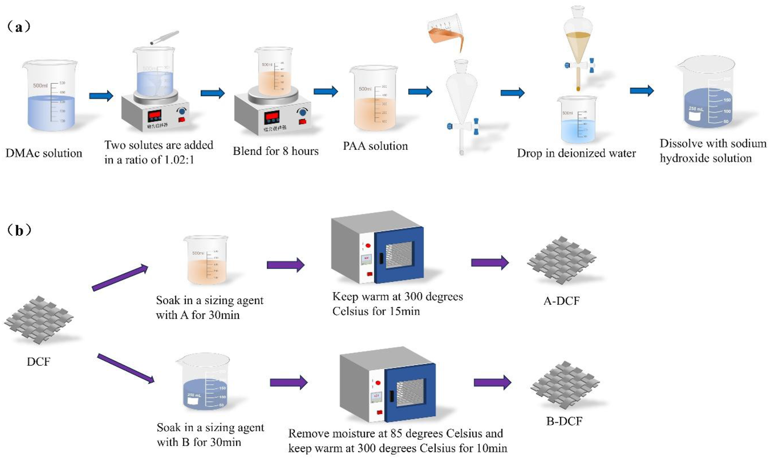
The sizing agent is prepared, and the carbon fiber is sized
The resultant organic solution of polyamide acid (PAA) was diluted to 0.5% weight and utilized as an organic solvent-based sizing agent A. A clear and stable aqueous solution was created by dissolving PAA powder in a diluted sodium hydroxide solution. The solution was then heated to 50°C, yielding an organic solvent-free carbon fiber sizing agent B (mass fraction adjusted to 0.5% Wt). Carbon fiber fabric (CF) was soaked in acetone for 12 hours, subsequently washed in deionized water, heated, and dried to produce bare carbon fiber fabric (DCF). DCF was then immersed in sizing agent A for 30 minutes, heated to 300°C, and maintained at that temperature for 15 minutes 38 to yield carbon fiber fabric with sizing agent A attached (A-DCF). The DCF was immersed in the B sizing agent for 30 minutes at 100°C to eliminate moisture, followed by heating to 300°C and maintaining that temperature for 10 minutes to produce the carbon fiber fabric with the B sizing agent (B-DCF), as illustrated in Figure 2(b).
Preparation of CF/PEEK composites
Carbon fiber fabric (CF) was precisely cut to a specified dimension, followed by the alternating lamination of CF and PEEK powder within a steel mold comprising 10 and 11 layers, respectively. The stacked board is moved into the flat plate vulcanizer at room temperature, applying an initial pressure of 0.1 MPa. Once the temperature of the equipment reaches 370°C, the pressure is adjusted to 1 MPa and maintained at this pressure for 30 minutes while keeping it insulated. After the system cools naturally to room temperature, the stacked board is removed, resulting in a uniformly flat composite material with a fiber volume fraction of approximately 50%. Subsequently, the fabricated composite boards were segmented into many sections. A range of composites was fabricated utilizing various fiber fabrics designated as CF/PEEK, DCF/PEEK, A-DCF/PEEK, and B-DCF/PEEK. Figure 3 illustrates the interfacial structure of CF/PEEK composites. Diagram of the interface structure of CF/PEEK composites.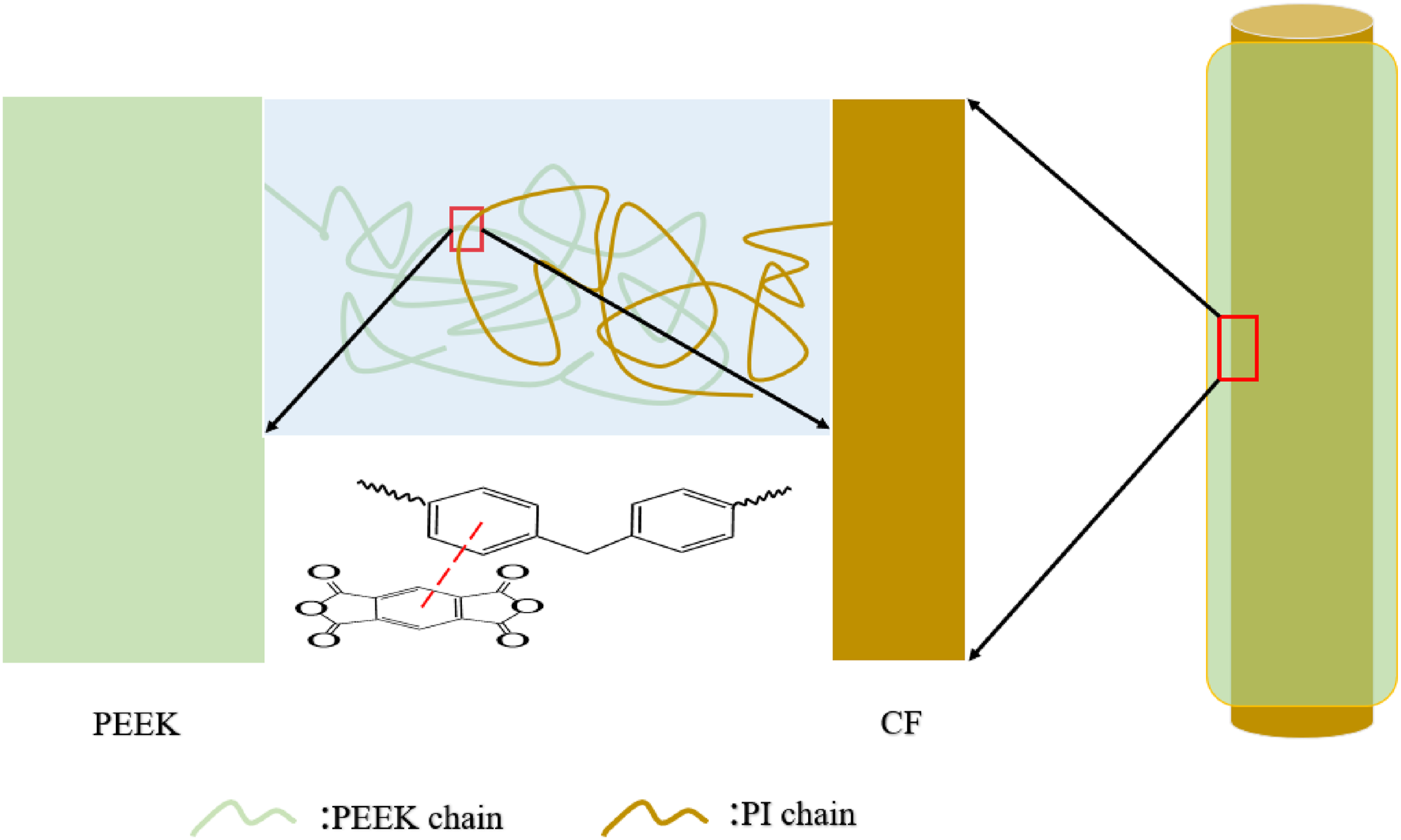
Characterization
Characterization of the chemical structure of carbon fiber surfaces
FTIR spectroscopy was conducted using a Thermo Scientific Nicolet IS20 with a resolution of 4 cm−1 and 32 scans. FTIR spectra were obtained in the range of 400-4000 cm−1 to evaluate the surface chemical structure and size influence of carbon fibers. X-ray Photoelectron Spectroscopy (XPS) was conducted using the Thermo Scientific K-Alpha (USA). The analysis chamber maintained a vacuum of 5 × 10^-9 mbar, utilizing an Al Kα radiation source (hv = 1486.6 eV). The voltage was set at 12 kV, with a filament current of 6 mA, and the signal was summed over five cycles. Examination (Successful-Energy) Full-spectrum scan: flux energy of 150 eV, step size of 1 eV; narrow-spectrum scan: flux energy of 50 eV, step size of 0.1 eV, with charge correction using C1s = 284.8 eV binding energy as the energy standard.
Three-point flexure test
The three-point bending test was conducted utilizing universal tensile testing equipment at ambient temperature by ASTM D790. A specimen exhibiting a span-to-thickness ratio of 32:1 was utilized in the test. In contrast, the holder and loading head of the test apparatus were circular with a radius of 3.0 mm. Throughout the examination, the specimen persisted in deflecting as the load was exerted until delamination or fracturing transpired, or until a maximum strain of 10.0% was attained. The tester produced an Excel file for each test, encompassing load and displacement data, with displacement representing the highest deflection of the specimen at the mid-span point. The load-displacement curve can be transformed into a stress-strain curve through the application of a formula to examine the material’s mechanical properties further. ASTM D790 provided items (1) and (2):


In the context, σ, f, ε, and δ represent the bending stress (MPa), bending strain (mm/mm), and beam center deflection (mm), respectively; F and L denote the load (N) and the span of the support (mm) at the specified moment; and B and h indicate the cross-sectional dimensions of the FML samples in mm. Five samples of each CF/PEEK composite plate were tested, and the bending strength was measured and averaged for plotting purposes.
Interlayer shear performance test
The fabricated CF/PEEK composites were evaluated for interlaminar shear strength (ILSS) qualities by the ASTM D2344 standard utilizing a short beam shear test method. The span-to-thickness ratio was 4:1, the length-to-thickness ratio was 6:1, and the width-to-thickness ratio was 2:1. When the plywood thickness was below 2 mm, the span, thickness, and length were extrapolated based on a thickness of 2 mm, with a loading rate established at 0.5 mm/min. Five tests were conducted to determine the average value. The ILSS(τ) was computed utilizing equation (3)

In this context, σ, f, ε, f, and δ represent the bending stress (MPa), bending strain (mm/mm), and beam center deflection (mm), respectively; F and L denote the load (N) and the span of the support (mm) at the specified moment, respectively; and B and h indicate the cross-sectional dimensions of the FML samples in mm. Five samples of each CF/PEEK composite plate were tested, and the bending strength was measured and averaged for plotting purposes.
Micro-morphological analysis
Powder samples were adhered to conductive adhesive and sputter-coated with a thin layer of gold utilizing a Quorum SC7620 coater. The coating was administered at 10 mA for a duration of 45 seconds. Morphological analysis and elemental mapping were performed using energy-dispersive X-ray spectroscopy (EDS) with a Hitachi Regulus 8100 scanning electron microscope.
Thermogravimetric analysis
A thermogravimetric analyzer (Rigaku TG/DTA 8122) was employed to assess and document thermal stability by weighing a suitable quantity of sample (5-10 mg for conventional samples and 2-3 mg for samples with special elements constituting less than 3%), uniformly positioned in an alumina crucible and heated in a nitrogen atmosphere at a designated rate of 20°C/min from 30°C to 800°C, with weight loss data recorded accordingly.
Results and discussion
Surface morphology of carbon fibers after sizing
The micro-morphology of the four carbon fibers (A, B, C, and D) post-treatment can be examined via SEM. The outcomes are illustrated in Figure 4. In Figure 4(a), the DCF represents carbon fiber subjected to high-temperature treatment, exhibiting distinct grooves and textures on its surface, a result of the PAN-based carbon fiber manufacturing process.
39
Figure 4(b) illustrates that the T300 grade carbon fiber production method results in a comprehensive coating that not only conceals the grooves of the PAN-based carbon fiber production process but also renders the surface smooth and even. The PI-sized carbon fibers depicted in Figures 4(c) and 4(d) exhibit a comprehensive coating of sizing agents on their surface. This coating not only obscures the majority of the grooves simultaneously but also preserves the irregular structure of the carbon fibers’ surface, resulting in enhanced surface roughness and consequently augmenting the contact area and adhesion among the carbon fibers. Figure 4(c) illustrates that the aggregation of the sizing agent has resulted in the creation of bumps on the surface of A-DCF. In Figure 4(d), the sizing agent is affixed to the surface and sidewalls of the B-DCF monofilament carbon fibers, and an aggregation phenomenon is also observed. SEM images of carbon fiber surfaces after sizing treatment: (a) DCF, (b) CF, (c) A-DCF, (d) B-DCF.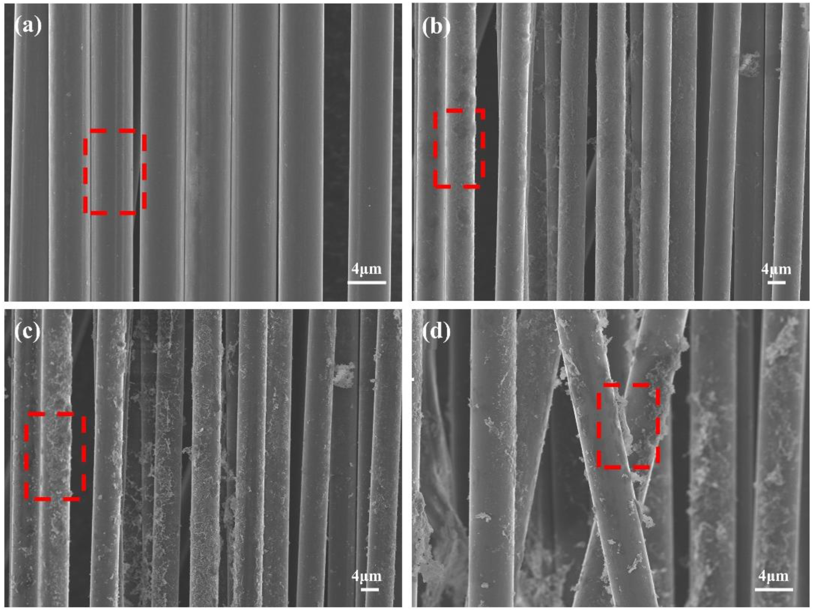
To more effectively examine the impact of the PI sizing agent on carbon fiber sizing, the surface morphology of monofilament carbon fiber was analyzed. Figure 5 illustrates the expanded surface morphology of an individual bundle of carbon fibers. After treatment with the sizing agent, the carbon fiber cross-section exhibits pronounced bumps and folds, obscuring the majority of the grooves while maintaining its irregular structure. The block structure created by the size agent in the next figure exemplifies a specific agglomeration phenomenon, resulting in visible bumps and irregularities on the surface. SEM image of a single bundle of carbon fiber after sizing treatment.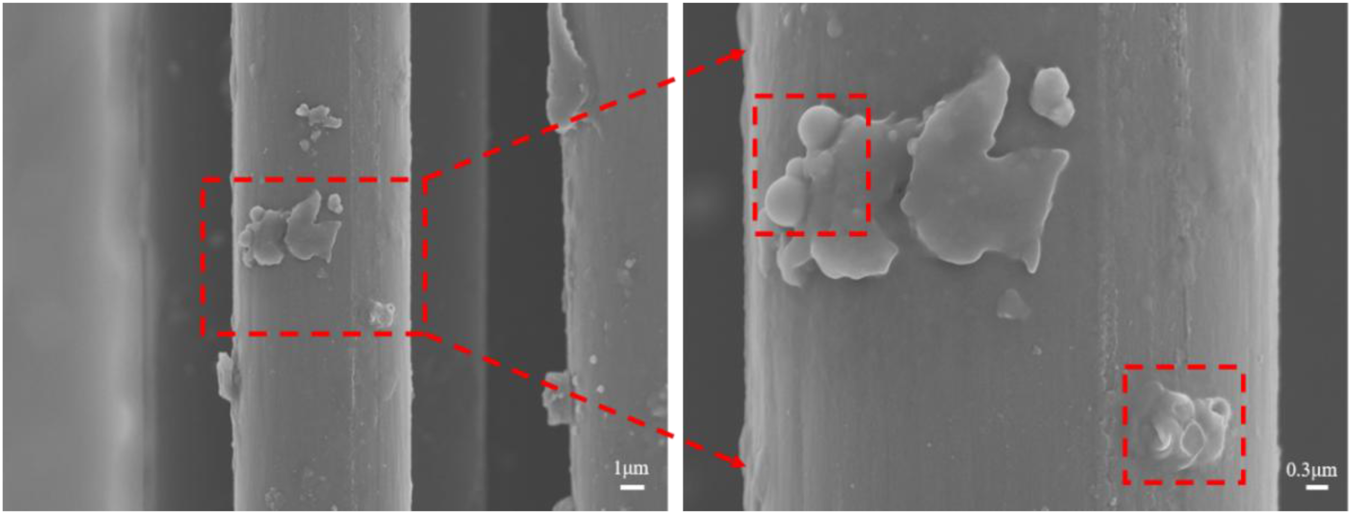
In conclusion, PI established a sizing agent layer on the surface and cross-section of A-DCF and B-DCF; nevertheless, it did not entirely obscure the surface grooves of the carbon fiber, preserving the inherent irregular structure of the carbon fiber. A significant degree of chemical substitution transpired on the original surface of the carbon fiber, leading to alterations to its surface chemistry. Nonetheless, this inclusion layer did not significantly influence the aggregation state and pliability of the carbon fibers, which were comparable to those of untreated carbon fibers (CF). The presence of PI sizing agents may influence the performance of carbon fibers in composites by modifying their surface activity, microstructure, and interfacial binding strength with the matrix.
The energy dispersive X-ray spectral picture reveals the distribution of carbon (C), nitrogen (N), and oxygen (O) atoms on the surface of the carbon fiber. Figure 6(a) illustrates the impact of layering the nitrogen and oxygen elements, revealing numerous elemental scatterings distributed across the carbon fiber surface. The structural formulae of the polyimide sizing agent suggest a synthesized agent that adheres to the carbon fiber surface. Figure 6(c) and (d) illustrate the spectrum images of nitrogen and oxygen elements, respectively. Carbon accounts for 91.42%, followed by nitrogen atoms at 4.75% and oxygen atoms at 3.83%. This distribution is attributable to the substrate being carbon fiber, with the weighted percentage of oxygen at 0.31%, significantly lower than that of the other two elements. This statistic indicates that the standard deviation of this element is reduced, the data dispersion is minimal, and the test value of elemental content is precise. The wt% Sigma of N is marginally greater than that of the other two components, potentially attributable to the solute impact during the synthesis of the PI sizing agent; nonetheless, it does not influence the overall data context. Energy dispersive X-ray spectral image of carbon fiber surface: (a) EDS scanning image, (b) C Element, (c) N Element, (d) O Element.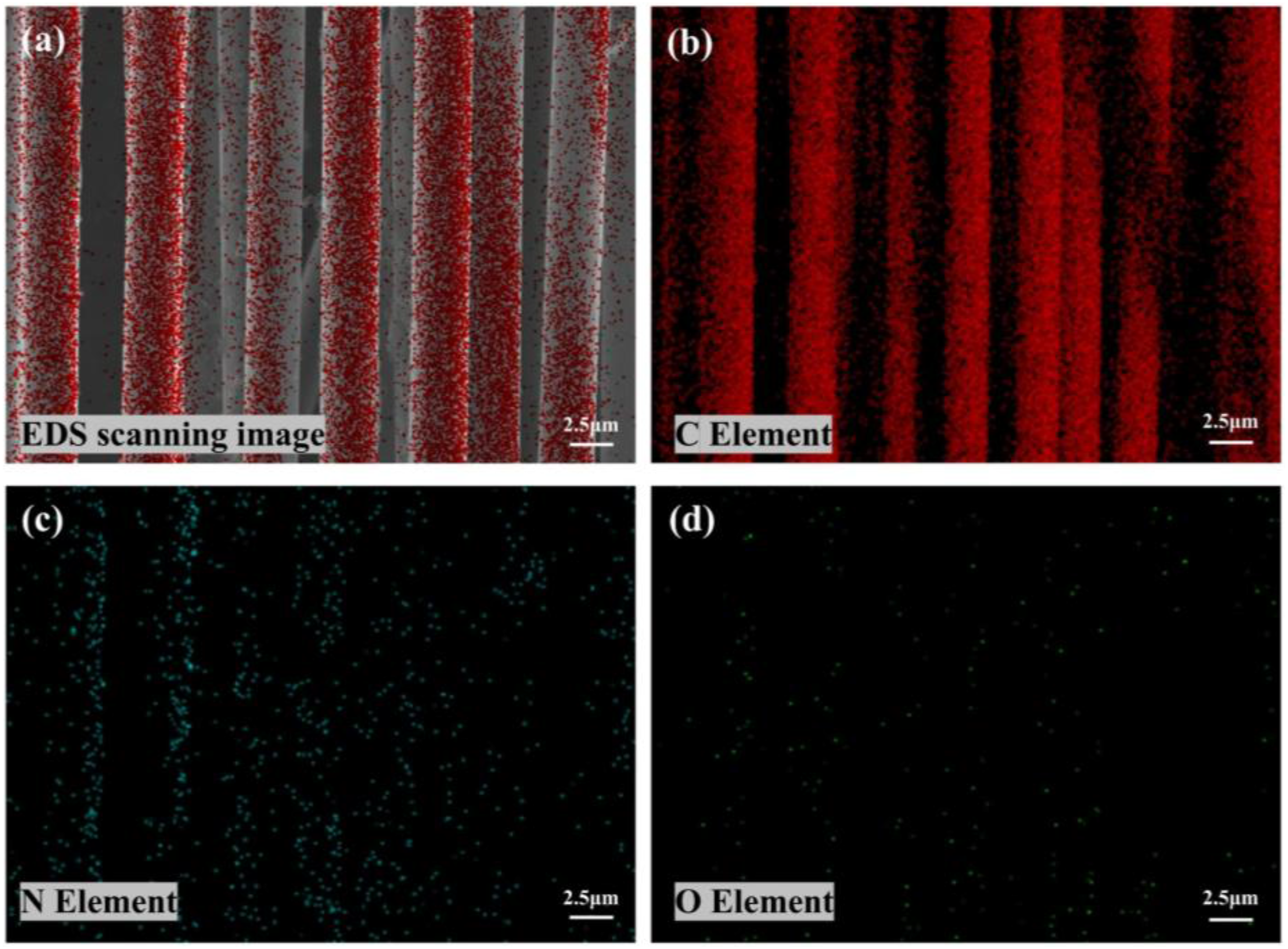
FTIR chemical structure analysis
Figure 7 illustrates that the FTIR spectra of DCF, CF, A-DCF, and B-DCF distinctly exhibit their unique absorption bands. The FTIR spectra of DCF exhibit absorption bands at 3720 cm−1, 1730 cm−1, and 1356 cm−1, which are attributed to the hydroxyl group (-OH), carbonyl group (-C = O), and carbon-nitrogen bond (-C-N),
40
respectively. The emergence of carbonyl absorption bands is intricately linked to the anodic oxidation phase of carbon fiber synthesis. In comparison to DCF, the IR spectra of CF exhibited characteristic absorption bands at 3720 cm−1, 1730 cm−1, and 1356 cm−1, with greater absorption intensities for the hydroxyl and carbonyl groups. This trend is primarily because of the application of a sizing agent on the surface of CF at the factory, which markedly enhances the quantity of polar functional groups present on its surface. FTIR spectra of different carbon fibers. PI: sizing agent.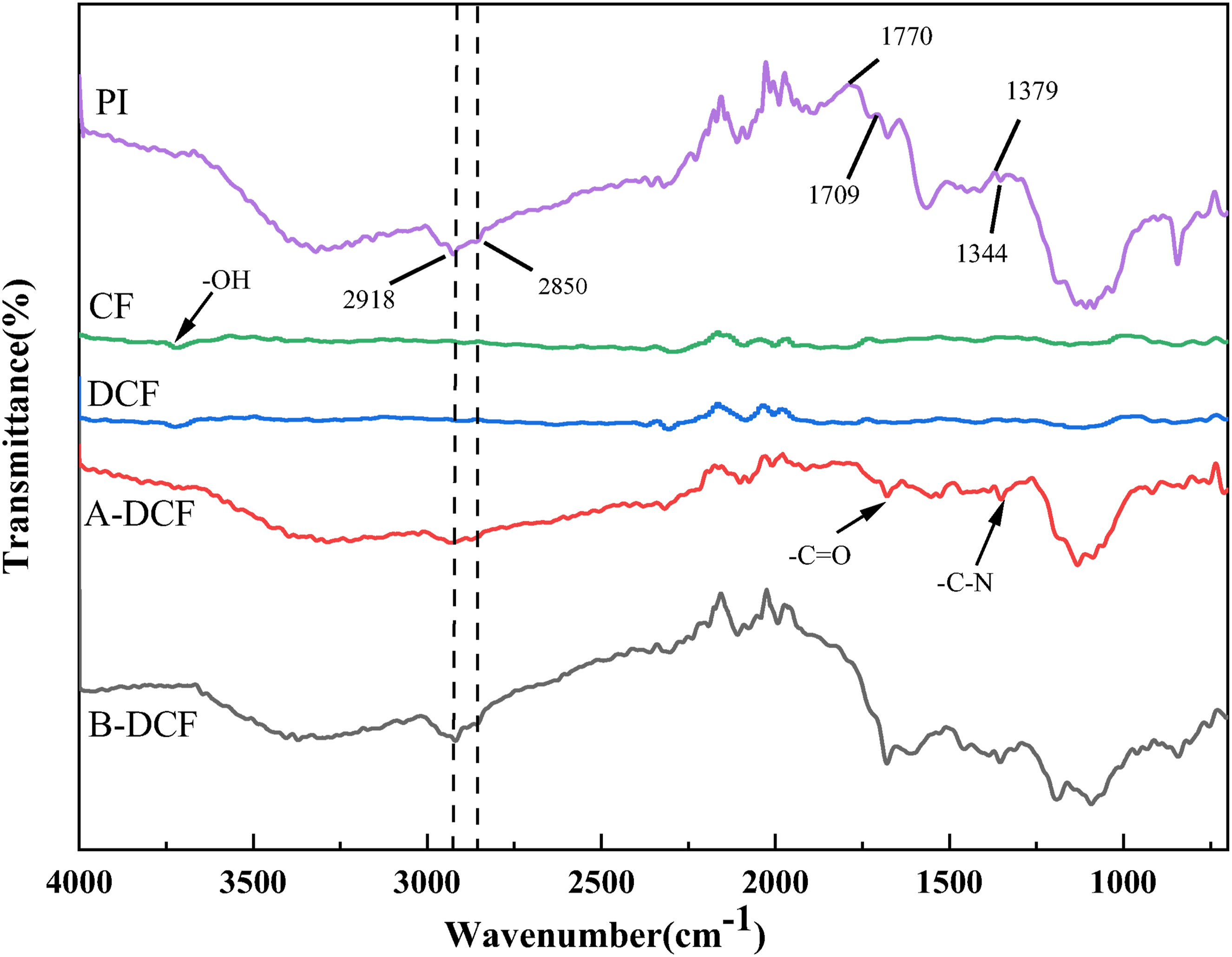
In comparison to the FTIR spectra of CF, the infrared spectra of the two sizing agent-treated carbon fibers, A-DCF and B-DCF, exhibited more pronounced typical absorption peaks of functional groups. The distinctive absorption peaks of carbon and nitrogen bonds (-C-N) and carbonyl groups (-C = O) were more prominent in the FTIR spectra of A-DCF. 41 Furthermore, two novel minor absorption peaks at 2918 cm−1 and 2858 cm−1 emerged, potentially associated with the chemical nature of the sizing agent. This finding indicates that sizing agents significantly influence the surface chemistry of carbon fibers. Sizing agents use a specific chemical reaction to add more polar functional groups to the surface of the fiber or the material matrix. This makes the absorption peaks in the FTIR spectra more pronounced and distinct.
The FTIR spectrum of polyimide (PI) reveals several characteristic absorption peaks, including carbonyl (-C = O) vibration peaks at 1770 cm−1 and 1709 cm−1, as well as C-N vibration peaks at 1379 cm−1 and 1344 cm−1. These distinctive peaks serve as crucial indicators of the molecular structure of PI, conveying information regarding its chemical composition and architecture. 41 The FTIR spectra of carbon fibers treated with sizing agents A-DCF and B-DCF exhibited vibrational peaks for carbonyl and C-N bonds that were akin to those of PI, with the intensities of these absorption peaks being more pronounced than those of untreated CF and DCF. A novel absorption peak at 2918 cm−1 was identified, owing to the -CH2 group within the MDA (methyldiamine) molecule.
The detection of -CH2 absorption peaks associated with PI in the infrared spectra of A-DCF and B-DCF provides additional confirmation of the successful synthesis of the PI sizing agent on the carbon fiber surface. The results indicate that the application of a sizing agent not only augmented the chemical activity on the fiber surface but also introduced additional polar functional groups via a unique chemical reaction pathway, leading to more noticeable, distinctive absorption peaks in the FTIR spectra.
Characterization of XPS
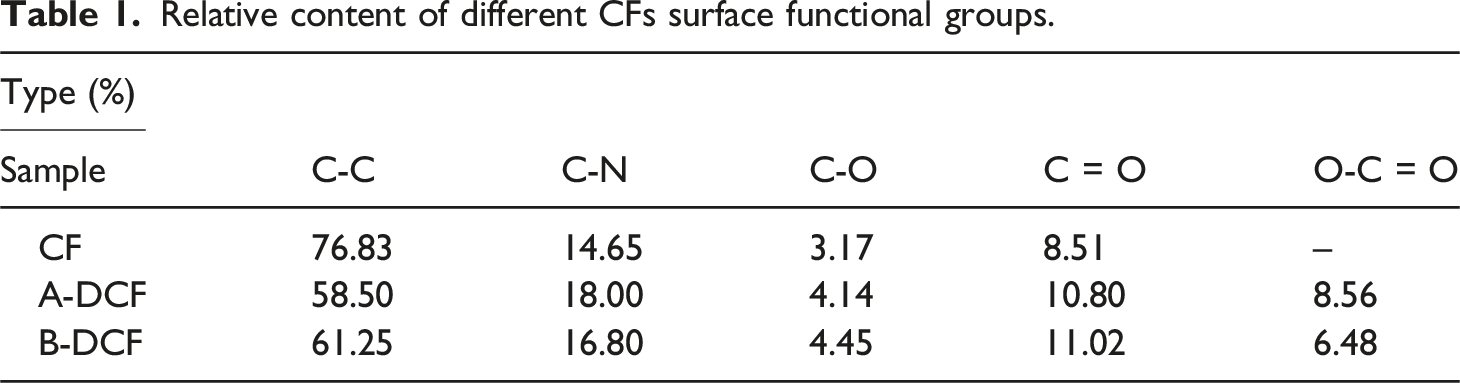
The X-ray apparatus employed a monochromator for broad-spectrum analysis of the carbon fibers, followed by a high-precision narrow-spectrum examination of the C, O, and N peaks to ascertain the surface chemical composition of the fibers. The C spectra was calibrated at a binding energy of 284.8 eV. The percentage contents of various functional groups on the fiber surface were ascertained by C1s top peak fitting. The compositions of CF, A-DCF, and B-DCF were assessed as illustrated in Figure 8. The oxygen-carbon elemental ratio of B-DCF attained 0.32, indicating the efficacy of the sizing process in enhancing the surface active groups of the otherwise inert fibers and surpassing that of CF. XPS analysis was employed to confirm the presence of the sizing agent on the CF surface by examining the elemental and bonding states. The chemical condition of the CF surface was quantitatively assessed through the narrow spectrum of C1s. Figure 8(d), (c), and (e) and Table 1 illustrate that the CF surface is inert, exhibiting a predominance of graphitic C-C structures (76.83%), alongside a little presence of C-N, C-O, and C = O structures. In the instance of B-DCF, following its sizing, the proportions of C-O (4.45%), C-N (16.80%), C = O (11.02%), and O-C = O (6.48%) groups exhibited a considerable rise (Table 1). The increase was ascribed to the presence of the sizing agent containing the imide ring and carboxyl group, signifying that the sizing agent had been effectively incorporated onto the surface. Split-peak fitting curves of C1s: (a) CF, (b) A-DCF, (c) B-DCF; XPS spectra of CFs: (d) CF, (e) A-DCF, (f) B-DCF. Relative content of different CFs surface functional groups.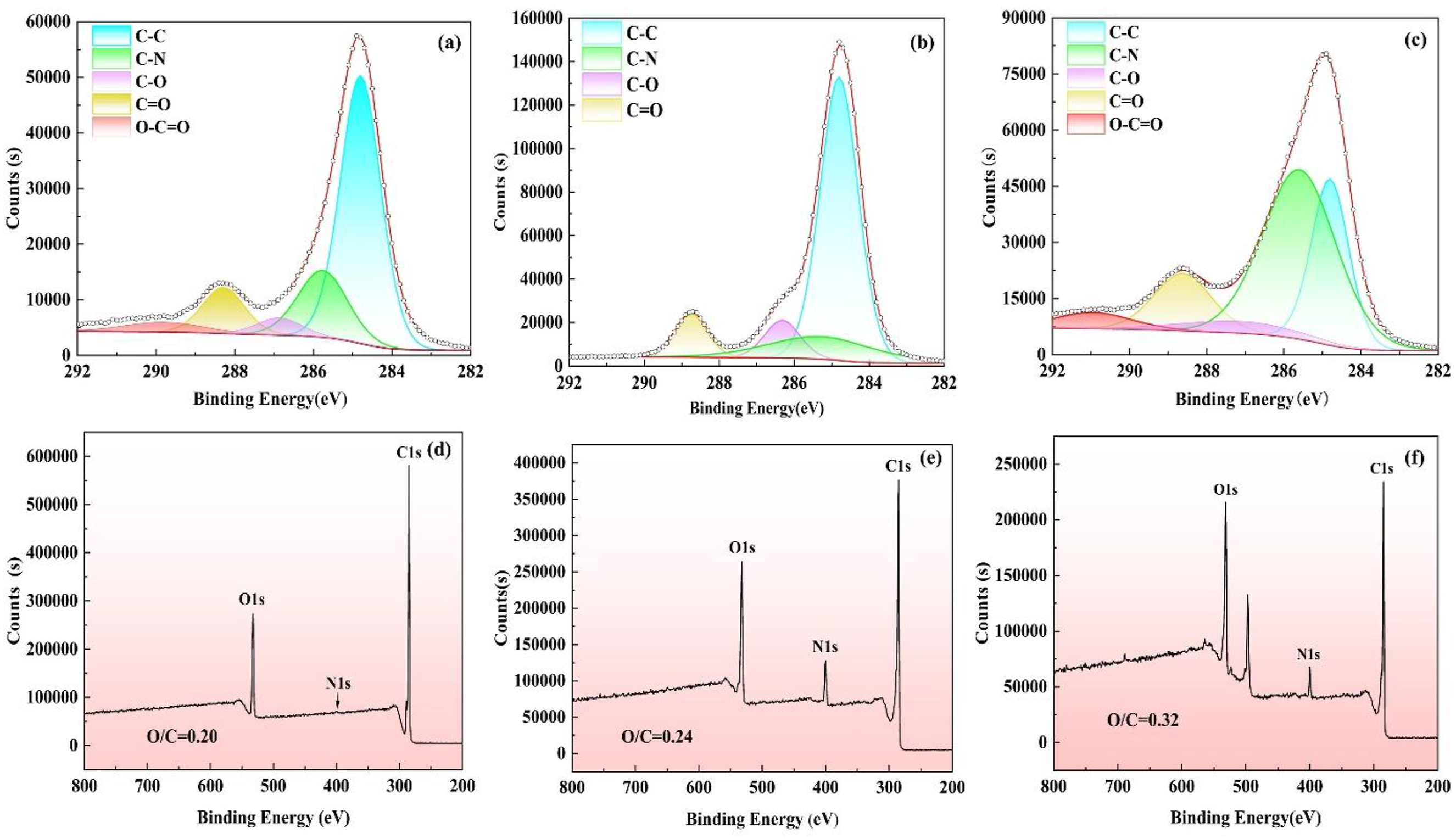
Thermal stability analysis
Figure 9 illustrates the thermogravimetric characterization of carbon fiber treated with a sizing agent in a nitrogen atmosphere. The B-DCF mass of carbon fiber reduces by about 2% at around 100°C, likely due to the volatilization of water adsorbed on the carbon fiber’s surface. With rising temperature, the mass loss of the sizing agent coating on the carbon fiber surface is gradual, totaling only 3.86% at 390°C, suggesting enhanced thermal stability of the carbon fiber post-sizing agent treatment. Conversely, the mass loss of the untreated CF occurred more rapidly within the temperature range of 200°C-400°C, exhibiting inferior thermal stability, likely attributable to the substantial decomposition of the epoxy-based sizing agent, which releases several small molecules.
42
Consequently, the interface of CF/PEEK composites was compromised during the molding process, potentially resulting in their mechanical properties being much inferior to those of other carbon fiber composites. Carbon fiber A-DCF exhibits structural similarities to B-DCF; however, it experiences a more rapid weight reduction post-500°C due to the volatilization of organic solvents. In conclusion, the thermal stability of the sizing agent coating on the B-DCF surface is superior. To examine the influence of sizing agent thermal stability on the formation of carbon fiber composites, the mechanical properties of four carbon fiber composites were subsequently evaluated. Thermogravimetric curves for different carbon fibers.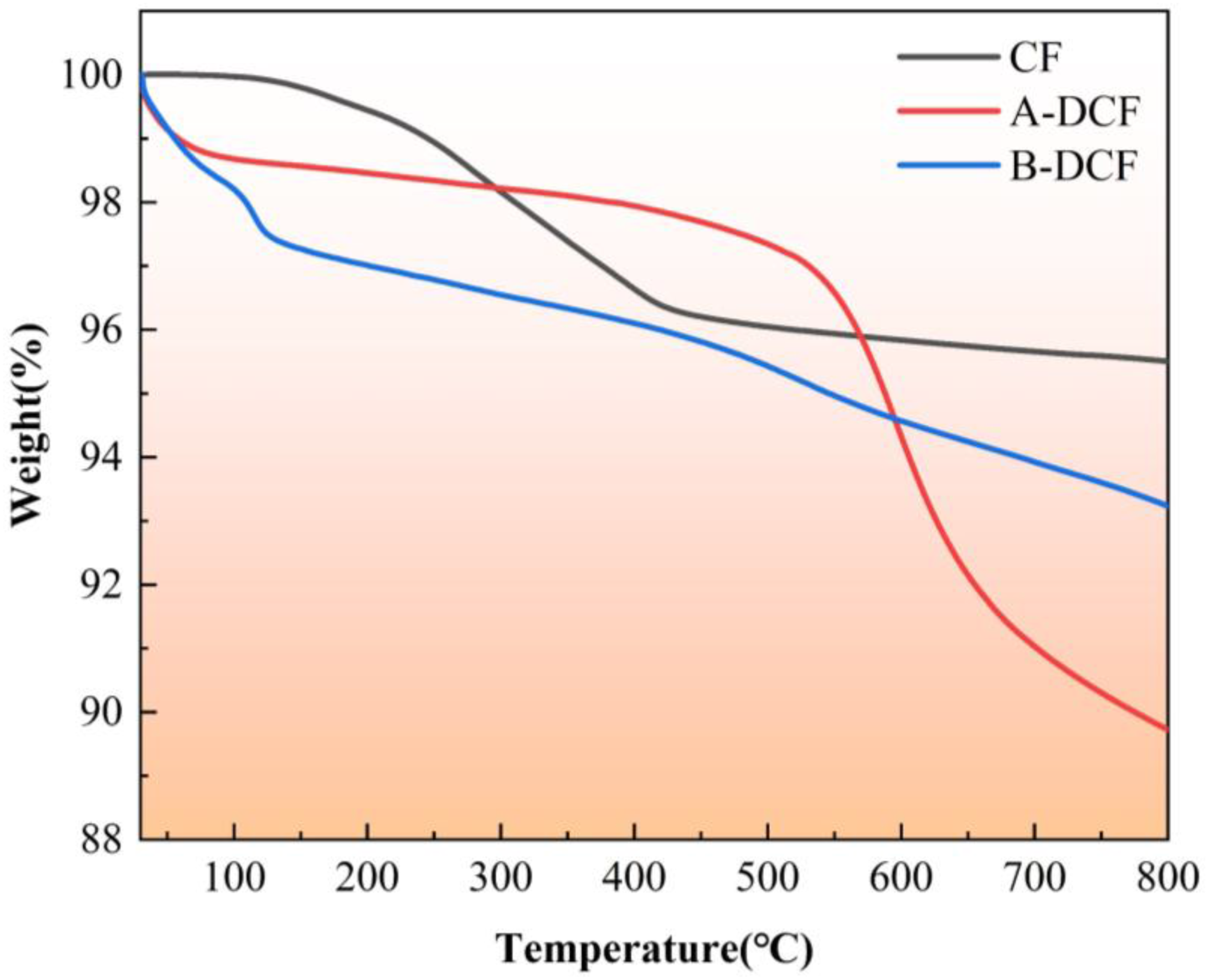
Mechanical properties of CF/PEEK composites
Figure 10(a) and (b) illustrate the flexural and interlaminar shear strengths of CF/PEEK composites subjected to various treatments, while the flexural and interlaminar shear strengths (ILSS) of the three composites, excluding CF/PEEK composites, exhibit varying degrees of enhancement. The A-DCF and B-DCF reinforced CF/PEEK composites exhibited greater enhancement. For instance, in comparison to DCF/PEEK, the flexural strength and interlaminar shear strength (ILSS) of B-DCF rose from 409.83 MPa to 24.03 MPa to 540.14 MPa and 40.45 MPa, respectively, reflecting increases of 58.62% and 40.59%. Conversely, the flexural strength and interlaminar shear strength (ILSS) of CF/PEEK diminished to 317.88 MPa and 22.97 MPa, reflecting reductions of 28.93% and 4.61%, respectively. The fracture stresses under three-point bending force are illustrated in Figure 6(c). In general, CF/PEEK composites have superior ductility, and the application of a sizing agent markedly influences the fracture strain of carbon fiber composites. The enhancement in flexural characteristics is attributed to the incorporation of a sizing agent that augments the bonding strength among the fibers, facilitating effective stress transfer between them. The sizing agent creates a superior interface on the carbon fiber surface, hence enhancing the flexural and interlaminar shear strength of the composites. Different bending test results for different carbon fiber reinforced CF/PEEK composites; (a) Bending strength, (b) Inter-ply shear strength, (c) Strain at break.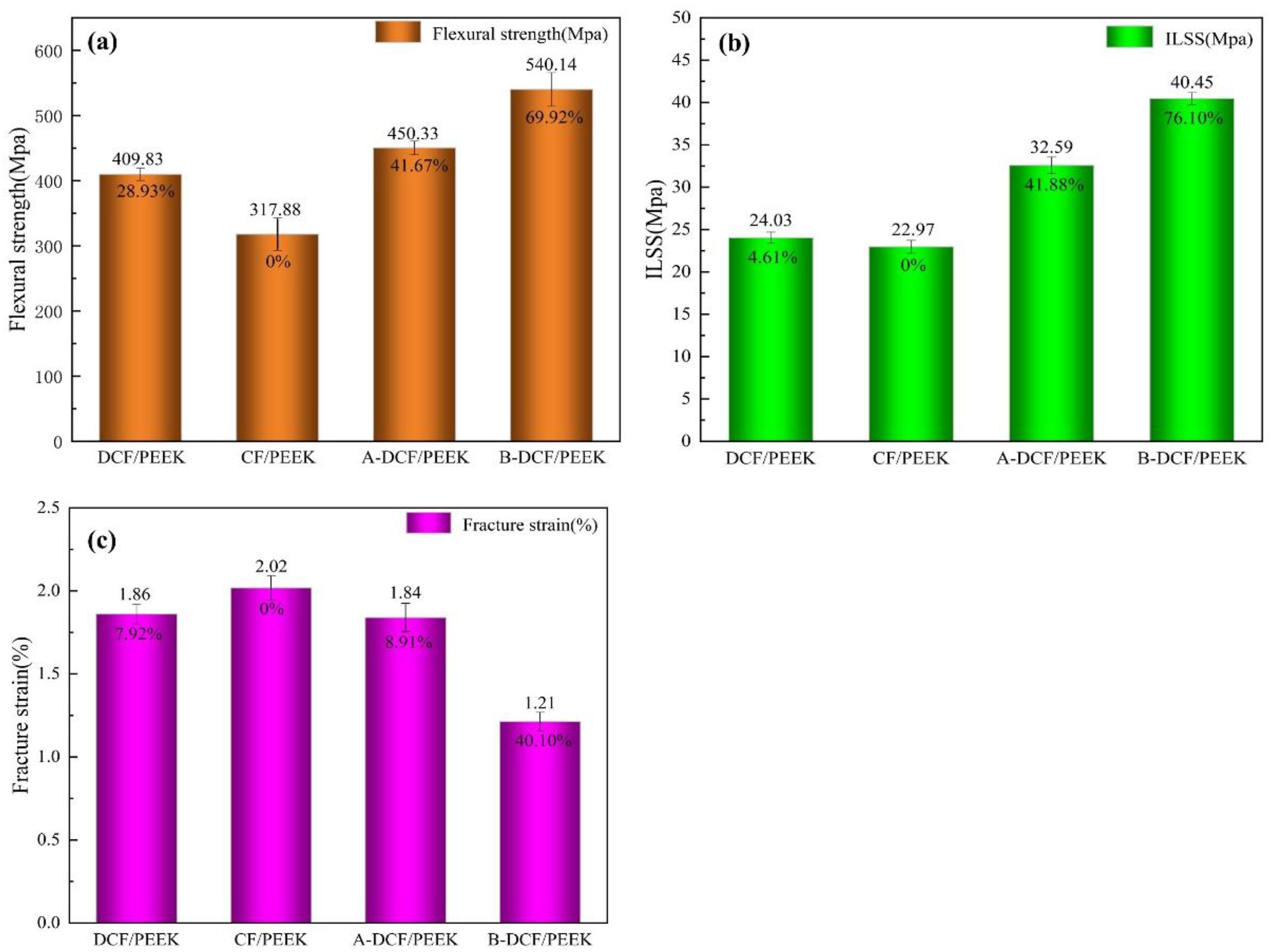
The initiation of the sizing process modifies the fiber surface characteristics via chemical and physical techniques; it augments the interaction between the fibers and the matrix and establishes effective interfacial adhesion, thereby ensuring a strong bond between the fibers and the matrix, which subsequently enhances the interlaminar shear strength and flexural strength of the composite. Nevertheless, the flexural strength and interlaminar shear strength (ILSS) of CF/PEEK composites were inferior to those of CF/PEEK composites. The issue may arise from the acquired T300 fibers being epoxy-sized and the sizing agent lacking adequate heat resistance, resulting in thermal decomposition during the molding process. The disintegration and generation of tiny molecules resulted in numerous flaws at the contact, corroborating the hypothesis derived from thermogravimetric analysis. Conversely, the B-DCF/PEEK composite demonstrated superior mechanical characteristics. The formation of a comprehensive coating structure on the carbon fibers’ surface results from the uniform dispersion of small molecules in the sizing agent, which fills the grooves on the fibers surface. This significantly enhances the interfacial bonding strength between the fibers and the matrix, thereby optimizing the composite’s overall properties.
Figure 11 illustrates the scanning electron microscope (SEM) picture morphology of several carbon fiber-reinforced PEEK composites at the point of fracture. Figure 11(a) illustrates the fracture morphology of DCF carbon fiber-reinforced PEEK composites. The image clearly illustrates that a majority of the carbon fibers are exposed over a substantial area, with only a minimal quantity of PEEK resin adhering to the surface of the carbon fibers. This phenomenon suggests a deficiency of evident interaction between the DCF carbon fibers and the PEEK resin matrix, indicating a weak interfacial connection. Conversely, a notable interaction exists between the carbon fibers (CF) and the PEEK resin matrix in Figure 11(b). This image exhibits an increased presence of PEEK resin residue on the carbon fiber surface, indicating superior interfacial bonding characteristics between the carbon fiber and the PEEK matrix.
43
The fracture morphology of A-DCF and B-DCF reinforced PEEK composites exhibited superior interfacial characteristics. The fracture of both materials reveals a substantial quantity of PEEK resin matrix adhering to the surface of the carbon fibers, indicating a notable improvement in the interaction between the A-DCF and B-DCF carbon fibers and the PEEK resin. This further demonstrates that the utilization of a sizing agent can significantly enhance the interfacial properties of carbon fiber (CF) and PEEK composites, hence improving the overall performance of the composites. Fracture SEM images of different carbon fiber reinforced composites: (a) DCF, (b) CF, (c) A-DCF, (d) B-DCF.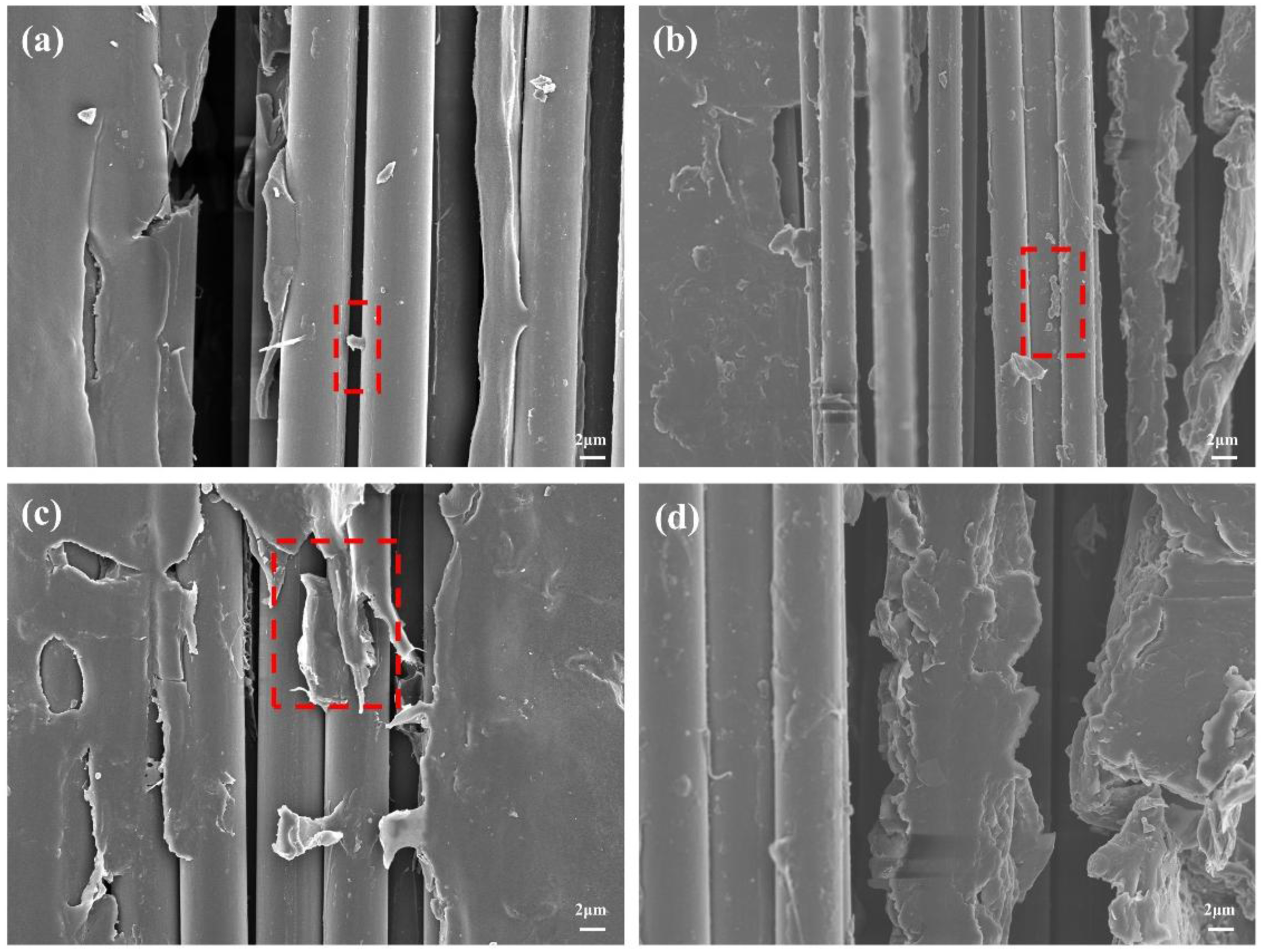
The mechanical properties of the composites and scanning electron microscopy (SEM) image analysis indicate that the interfacial properties of the B-DCF composites exhibit considerable advantages. Initially, the naked carbon fibers (D-CF) successfully established strong adhesion with the sizing agent via intermolecular forces. Secondly, the polyimide sizing agent exhibits excellent intermiscibility with the PEEK resin, resulting in molecular chain entanglement that substantially improves adhesion. Furthermore, due to the polyaromatic ring structure of the two resins, π-π stacking interactions among the molecules may occur. The application of a polyimide sizing agent as a ‘bridge’ between carbon fiber (CF) and PEEK resin can significantly enhance the interfacial characteristics of CF/PEEK composites. 44
Schematic diagram of reinforcement mechanism of CF/PEEK composites
To better understand the mechanism by which polyimide sizing agents enhance the mechanical properties of CF/PEEK composites, the potential surface structures of carbon fibers were analyzed, as shown in Figure 12. Polyimide and the PEEK matrix share similar chemical structures and exhibit excellent compatibility. They achieve strong interfacial bonding in the composite through polymer chain diffusion and entanglement. The polyimide sizing agent firmly adheres to the carbon fiber surface via π-π interactions and intermolecular forces. Furthermore, potential hydrogen bonds between the sizing agent and the PEEK matrix further enhance the interfacial bonding. Schematic diagram of PI sizing agent interface reinforcement mechanisms of CF/PEEK composites.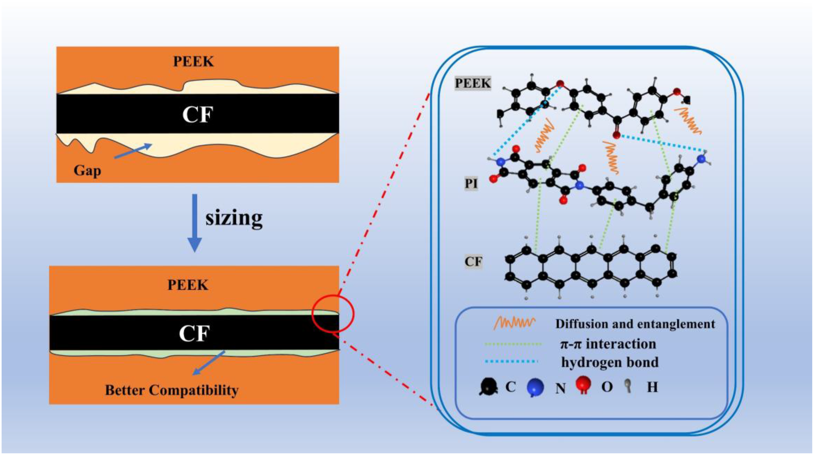
Conclusions
This study successfully increased the interfacial and mechanical properties of carbon fiber reinforced polyether ether ketone (CF/PEEK) composites through the surface modification of carbon fiber (CF) using a synthetic polyimide (PI) sizing agent. The organic solvent-free aqueous polyimide sizing agent (B-DCF) created a uniform and stable coating on the carbon fiber surface, markedly improving the interfacial bonding strength between the fibers and the PEEK matrix via physical entanglement and π-π stacking. SEM and FTIR analyses confirmed that the sizing agent effectively filled the grooves on the carbon fiber surface and introduced polar functional groups while preserving the fibers’ microroughness, thereby optimizing interfacial load transfer efficiency. The efficiency of interfacial load transfer was optimized. The mechanical property tests indicated that the bending strength and interlayer shear strength of B-DCF/PEEK composites attained values of 540.14 MPa and 40.45 MPa, respectively, representing increases of 69.92% and 76.10% compared to CF/PEEK. The solvent-free sizing procedure introduced in this work addresses the safety and environmental concerns associated with previous methods while simultaneously offering an effective solution for high-performance CF/PEEK composites. The solvent-free sizing process presented in this study addresses the safety and environmental concerns associated with traditional methods while also offering a theoretical foundation and technical assistance for the utilization of high-performance CF/PEEK composites in high-temperature and high-load applications, such as aerospace.
Footnotes
Author contributions
Sensen Han: Data curation, formal analysis, writing—original draft, writing—review & editing.
Zhanjun Liu: Conceptualization, Methodology.
Meng Cao: Methodology, Data curation.
Zhiqi Ding: Data curation, writing—review & editing.
Shuo Wang: Project administration, resources, supervision.
Xiaodong Li: Project administration, resources, supervision.
Declaration of conflicting interests
The authors declare that they have no known competing financial interests or personal relationships that could have appeared to influence the work reported in this paper.
Funding
The authors disclosed receipt of the following financial support for the research, authorship, and/or publication of this article: This work was financially supported by the Natural Science Foundation of Liaoning Province (2025-MS-129) and the Shenyang Science and Technology Plan Project (24-213-31).