
Abstract
Three-dimensional fabrics have an enormous potential for the manufacturing of semi-finished products in a direct preforming procedure for fiber-reinforced materials. The production of these three-dimensional fabrics involves the processing of coarse reinforcing yarns with high warp density. However, conventional weaving looms have not been designed for such applications, and their maximal achievable warp yarn density is therefore severely limited. Friction and clamping between warp yarns impede the shedding process, and fragments of damaged or fibrillated fibers interfere with the weaving process. Most of the solutions for these issues, which has been presented so far, are based on noncommercial technologies or require extensive modification on standard weaving machines. Hence this paper proposes a new shedding method based on double flat steel heddles, which is suitable for the use in conventional weaving looms. The paper gives a detailed description of the new shedding method including the required materials and the technological framework. Furthermore, a suitable algorithm for the fast pattern conversion under consideration of the special technological framework and requirements of the shedding is presented.
Keywords
Introduction
High performance textiles consisting of glass, carbon, and aramid fibers are used extensively for the production of fiber reinforced plastics (FRP), which are applied in the aerospace and automotive industries as well as in mechanical and civil engineering. These reinforcement textiles can be manufactured by various textile production techniques, such as weaving, weft and warp knitting, as well as braiding. Among the productivity and the achievable mechanical properties of the later fiber reinforced component, the geometrical variety of the textile preform depends largely on the used technology [1–4]. Weaving technology enables the efficient production of two-dimensional (2D) reinforcing fabrics with adjustable drapeability for sequential preforming as well as three-dimensional (3D) fabrics for direct preforming within the form of near-net-shape structures [5].
2D woven fabrics (in following: 2D fabrics) consist of a single warp and a single weft yarn layer. In consequence, orientation and reinforcing effect of the fibers run in the in-plane direction only. In contrast, 3D woven fabrics (in following: 3D fabrics) consist of several weft and warp yarn layers with additional yarns in the thickness direction (out-of or z-direction). The properties of 3D fabrics can be adjusted specifically to each individual application in the in-plane as well as out-of-plane directions by means of weave patterns, layer structures, and choice of materials [6]. Moreover, 3D fabrics can be formed according to the desired FRP component geometry even during the weaving process, e.g. in the form of spacer, shell-shaped, node, and profiled fabrics [7–11].
In comparison to conventional reinforcing materials (e.g. 2D textiles, prepregs), composites reinforced by 3D woven fabrics have a considerably improved resistance against delamination and impact load. They are suitable for a wide range of applications due to highly flexible weave patterns [12,13]. However, the production of such near net shape preforms with a high number of different layers is only possible using special weaving loom as shown by Mohamed and Zhang [14] and Khokar [15]. Although several past projects have focused on different types of these special weaving looms, their industrial use focuses on special application like the woven carbon fan blade by Albany/Safran [16,17]. However, the required weaving technology itself is not commercially available [18,19].
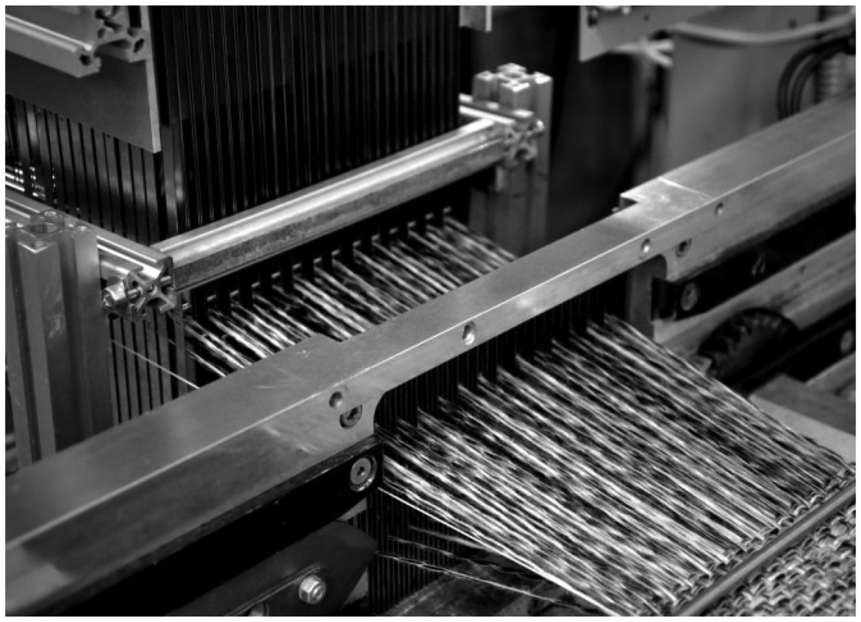
But, using standard weaving loom with conventional set up for the production of 3D weaves leads to a large number of problems. The required warp density increases extremely (24 yarns/cm and higher) with the complexity and desired wall thickness of the 3D woven fabric in connection with a high yarn count (e.g. carbon 800–3300 tex) at the same time. Consequently, the warp yarns cling together and they degrade into filaments due to intense friction at the heddles and the reed as well as friction between the warp yarns changing shed positon. Moreover, fiber fragments of the heavily stressed warp yarns accumulate on heddles and reed dents. These effects impede the weaving process and make the processing of 3D fabrics on standard looms nearly impossible. The underlying cause has been pointed out by Archer et al. [20], Lee et al. [21,22], Rudov-Clark et al. [23], and Lefebvre [24]. The results of these effects and the shedding geometry are presented in detail in Figure 1.
Yarn degradation and shedding geometry while 3D weaving on a standard loom.
These effects restrict the process efficiency of 3D fabric manufacturing. Therefore, industry and research have presented various approaches to resolve these issues. For example, manufacturers of weaving looms have developed specific types of looms, where the process of weft insertion is distributed over two or more insertion systems. Thus, warp yarns can be placed in three or more shed positions, which lower the yarn density per shed position [25–27]. Another approach has been presented by Decrette (2014) using a Stäubli Unival 100 jacquard unit with individual yarn control which is variable in position and phase. It has been proven that an offset of the shed lift of adjacent warp yarns has a positive impact on process stability [28]. Chiu and Cheng [29] have investigated the use of special heddles with several eyelets located on top of each other. Hence, warp yarns in 3D fabrics can be arranged in a staggered manner during shed formation. However, the application of these heddles either demands the use of several weft insertion levels or a shaft drive powered by a servo motor and a special jacquard machine, respectively.
Analogous to the lack of a suitable shedding unit for the production of 3D fabrics, there is also a lack of feasible methods for the derivation of weave patterns as well as the programming of shedding control for 3D fabrics. The programming of the pattern control is mainly based on the pattern plot as data input, which only contains information on warp lifting and lowering. Approaches for a software-supported derivation of pattern designs for conventional 2D fabrics apply this information and therefore represent them as a 2D matrix with the entries 0 (heddle lifting) or 1 (heddle lowering) [30,31]. The representation and description of weave patterns must therefore be extended to become applicable to 3D weaving. Potential solutions have been presented by Lomov et al. [32] (matrix notation system), Chen [33] (extended pattern plot), and Boussu et al. [34] (encoded notation). The matrix coding system of Lomov and Gusakov essentially describes the path of warp yarns within a fabric unit cell and is already in use for the engineering software WiseTex. The extended notation by Chen is compatible with machine control, but not suitable for the efficient description of complex 3D fabric structures. The method of Boussu is based on a range of previously declared terms and typologies of various 3D weave patterns. However, there are still no methods and algorithms to effectively process 3D weaving patterns for direct data input into the control systems of standard weaving looms.
Hence, in this paper, a special shedding method based on special heddles for conventional weaving looms is introduced. By means of this special new shedding system, current deficits in the production of 3D fabrics, e.g. limited warp density and high yarn damage, can be effectively eliminated. The implementation of the shedding unit is described by means of a jacquard weaving loom, and the first produced structures are presented. An essential feature of the shedding method is a significantly changed yarn draft. Therefore, this paper continues to identify the technological framework in order to prevent disturbances in the weaving process resulting from inadmissible shedding variations. The results of this analysis will be further used for the development of a new algorithm to derive weave patterns for machine control. This algorithm also allows its effective integration into the engineering workflow for the design of 3D fabrics.
Implementation of the new shedding method
Heddle position and warp yarn draft
Using standard heddles, every warp yarn runs at the same level as the heddle wire by means of weft direction (y-axis). As a result, each warp yarn needs to avoid contacting the heddle of the adjacent warp yarn. The density of the warp yarns in the shedding area can only be increased by offsetting certain heddle clusters. However, this is a limited approach since every warp yarn position still has to be offset in the weft direction. The warp yarn positions in the weaving shed can only be adjusted approximately to the yarn positions of the 3D fabric, depending on yarn count, weave pattern, and warp density (Figure 2). In addition to their staggered draft in z-direction, they also have to be separated on different frames in machine depth direction (x-direction, referring to Figure 1). The final positioning of warp yarns within the fabric depends on the beat-up of the reed and shed changes. This results in fiber damage due to fiber-to-fiber friction. Options for reducing warp yarn degradation are thus strictly limited in the case of conventional weaving heddles.
Warp position in relation to heddle position.
In contrast, double flat steel heddles form the basis of the here presented new shedding method. They are commercially available as TWINTec or double weaving heddle [35,36]. Their main feature is that they consist of two metal strips and two pins, functioning as a heald eye. By a suitable arrangement of the heddles, an arrangement of yarns can be generated exactly one above the other (Figure 2). Relating to the draft of heddles and warp, this enables the precise positioning of the yarns according to their desired position within the 3D fabric. Warp yarns no longer need to be offset in the weft direction. Instead, they run one above the other through the heddle of the adjacent warp yarn. This method of yarn arrangement enables the vertical staggering of the warp yarns in the z-direction (Figure 3). However, the premise for a minimum damage of the yarns passing the heddles is the accurate alignment of each heddle row to prevent multiple contacts.
Heddle and warp position using double flat steel heddles.
Combined with a defined height offset, it is now possible to vertically stagger the warp yarns in the z-direction (Figure 3). The schematic illustration given in the figure displays the arrangement of heddles, yarns, and the fabric in principle. The geometrical setting between these components—completed by the reed and weft insertion—allows a sequential shedding of each weft level so that complex 3D fabrics can be produced with just a single weft insertion system.
This arrangement accurately reflects the positioning of warp yarns in the 3D fabric. Subsequent shifting of warp yarns at the reed dents has become redundant. Negative effects caused by clamping and friction between warp yarns can be minimized, and warp density can be considerably increased. In addition to technological flexibility, another main advantage of this shedding system is its transferability to already existing, conventional weaving looms. Double flat steel heddles are available as part of the standard equipment for various types of weaving looms so that they can be utilized without any additional equipment. Existing devices, such as dobbies and jacquard units, can still be used. Time and efforts required for setting up and installing the heddles and few guiding elements are reduced to a minimum. As required for any weaving system—both for 2D and 3D fabrics—each warp yarn system requires a separated and appropriate equipment for warp yarn feeding, Taking that into account, the proof on the concept of the new shedding method (as shown in “New shedding method and processed samples” section) has been done with creels. However, the use of warp beams (one beam for each warp yarn system) with the new shedding method is possible as well.
New shedding method and processed samples
In order to test the developed shedding system with double flat steel heddles, a MAGEBA shuttle weaving loom with 140 mm working width was modified accordingly. The standard jacquard unit of the selected weaving loom comprises 448 heddles in total, 324 (27 columns, 12 heddle rows/warp yarn positions) of which were replaced by the new heddles (see Figures 4 and 5). Therefore, the remaining heddles serve the integration of binding warp yarns that pass through all layers. They can be placed either in front of or behind the double flat steel heddles.
Side view of the shedding method at ITM. Front view of the shedding method at ITM.
According to the layer number of the guided warp yarn, the height of each heddle has been adjusted as shown in Figure 3. Furthermore, heddle guiding elements have been installed above and below the heddle eyes. This separates the heddles rows and thus ensures process reliability. However, this is not required for the use of heddles in dobby machines.
The new shedding method was successfully tested by means of various yarn materials (filament yarns and staple fiber yarns) and subsequently put into operation.
Proof of concept has been provided by successfully weaving different multilayer 3D fabrics based on 660 tex polyester yarn with a warp density of 24 yarns per cm. That includes typical 3D fabric like the Layer-to-layer warp angle interlock and a less typical Through-the-thickness weft angle interlock with completely non crimped warp yarns. The weft has been inserted parallel to y-axis by the single shuttle system of the used MAGEBA weaving loom. Geometrical models and the produced samples, cured with epoxy resin for better visibility, are shown in Figures 6 and 7.
Sample layer to layer – warp angle interlock (left: geometrical model with six warp yarn layers; right: cured farbic sample with 12 warp layers). Sample through the thickness – weft angle interlock (left: geometrical model with six warp yarn layers; right: cured fabric sample with twelve warp yarn layers).

The sample shown in Figure 7 features a special binding structure, in which yarn layers are not locked by a binding warp yarn system. Rather, the 3D fabric is locked by the interlocking weft yarn system, and all warp yarns run mechanical advantageous without crimp through the fabric. This fabric type can be produced by the simultaneous shedding of all heddles in one warp column, especially by using the mentioned new shedding method.
In combination with a jacquard machine, the shedding method provides a high flexibility for the production of 3D fabrics with a characteristic layered structure. Even interlaced weaves such as Orthogonal bindings and Through-the-thickness warp interlock can be produced by adding wire heddles behind the shedding, which guides the binder yarns through the heddle rows. However, it has to been taken into account that the new method is not suitable for the production weaves which require the crossing of warp yarns within a heddle row.
The limitation of the warp density currently amounts 24 yarns/cm. It is possible to achieve higher warp densities by adding more heddle rows in the warp direction. Furthermore, the staggered warp yarn drawing considerably eases the insertion as well as the repair of damaged warp yarns. Therefore, each heddle row is lifted separately, and the warp yarns can be drawn in column-wise in a fast and accurate manner. Moreover, the affected heddle row can be identified easily within the shedding system, and the defect can be eliminated with minimal effort.
In contrast to conventional shedding (Figure 2), every yarn within one heddle row has to run parallel to the other, considering that their crossing is not possible and the application of the new shedding method is primarily suitable for 3D woven fabrics and their characteristic layered structure.
Technological framework and algorithm for pattern derivation
Technological framework
Definition of heddle position
In order to determine basic technological requirements of the shedding system, the heddle lift procedure within a warp yarn column needs to be considered first. Several essential terms are presented in Figure 8. Moreover, this figure shows the numbering of the heddles, referring to the standard counting method in jacquard weaving.
Numbering of heddle positions.
Provided that a warp yarn is never deflected by two heddles, every heddle position can be assigned to a certain warp yarn. Due to the coding of the weave pattern as a pattern plot, each heddle (and thus each warp yarn) can be assigned to a defined position during weft insertion. Therefore, all heddle positions per weft row are aligned in the pattern plot. As an example, the heddle numbering system is presented in Figure 9 for three heddle rows.
Warp yarn numbers referring to heddle position.
This definition enables the description of the heddle’s position in each shedding variation. The applied method can be extended to heddle rows of any size and forms the basis for all further investigations described in this paper.
Identification of the relevant shedding variations
The basic structure of the described shedding system enables the simultaneous deflection of one warp yarn by several heddles. These heddle lift positions need to be avoided for flawless procedures. Otherwise, multiple deflections will result in significantly increased friction between heddles and warp yarns as well as between warp yarns within one heddle column. Consequently, tensile forces of the warp yarns spread unevenly in the y-direction, irregular fabric structure and degraded warp yarns, as well as disruptions of the weaving procedure, occur. In particular, when using a jacquard machine for shedding, there is a plurality of possible combinations regarding the deflection of heddles. Most of them are technologically irrelevant and do not meet the criteria of single yarn deflection. Thus, the following sections will focus on the question which heddle lift sequences can be determined for any number of heddle rows per column. As an illustration, the shedding with three heddles per column is used (Figure 10).
Cross-sectional view of shedding with three heddles per column.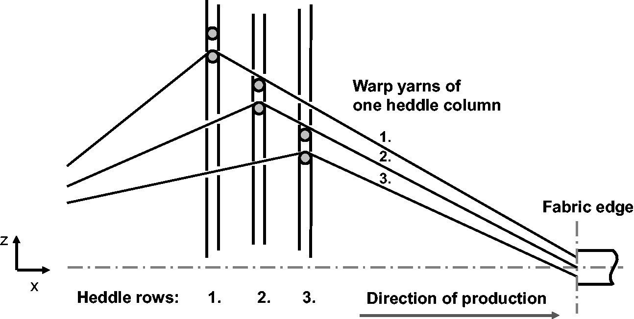
Default shedding system (jacquard machine or dobby) allows only two positions (upper or lower shed position), so the number of different combinations of deflected heddles nc results from the number of heddles nh per column using the following equation:

The resulting eight possible heddle lift combinations (in the case of three heddles per column) are presented schematically in Figure 11. It must be pointed out that the presented and described multi defection of warp yarns only occurs using the new shedding method. In contrast, the staggered draft of conventional heddles (see also Figures 1 and 2) prevents that.
Shedding variations for three heddles per column using the new shedding method.
Switching states referring to heddle position.

Truth table of the shedding variations.

The results of the truth table can be summarized using the term f to describe the switching function. As described in Table 2, f becomes the value 0 (irrelevant), if the shedding variation k includes multi deflection of warp yarns. Otherwise, it becomes the value 1 (relevant). The heddles lift combinations that appear technologically feasible deliver 1 as a result. If a part of a relevant combination contains the value 0 (lower shed position of heddle), the inverted input variable (
This form equals the canonical disjunctive normal form (products of input variables) [35]. Here, the so-called min-terms that have a switching function of 1 are linked by OR operations. They can be reduced to the following formula by means of Boolean algebraic principles [37]:

The same relation can be described using another normal form, more precisely, the canonical disjunctive normal form. In contrast to the disjunctive normal form, it contains max-terms linked with AND, which have a switching function of 0. The following formula refers to the specific example (check figure 11):

Using the principles of Boolean algebra, it can also be simplified to the following equation:

In general, the variants of a disjunctive normal form provided in equations (2) and (3) present the technically relevant heddle lift combinations. With a rising number of heddles per heddle column, complexity increases as well. This is shown by means of a shedding system with four heddles per column in the following equation for the disjunctive normal form:
Canonical disjunctive normal form
Simplified disjunctive normal form
The same applies to the canonical conjunctive normal form. Since the number of possible heddle lift combinations rises exponentially with the number of heddles per heddle column, it extends even stronger than the disjunctive normal form. However, the simplified conjunctive normal form can be expanded by only one term per additional heddle. Also, its structure indicates the general laws that determine how to execute the heddle lift, regardless of the number of heddles

Four heddles per column:

Five heddles per column:

The requirement that a warp yarn is not being deflected by several heddles is fulfilled simultaneously if the subsequent heddles are placed on the same or a lower shed position. For any number of heddles within a heddle column, the simplified conjunctive form of the switching function reads as follows

Whereas the number of heddle lift combinations rises exponentially in parallel to an increasing heddle number per column, the number of technologically relevant variants 
The example (three heddles per column) discussed so far contains four technologically relevant shedding variations (see Figure 12). The illustration next to the shedding variation represents a partial pattern plot for the heddle lift of a heddle column. This factor has been taken into consideration for the following conversion algorithm of complex 3D fabric patterns using the new shedding method.
Relevant shedding variations for three heddles per column and resulting pattern.
Algorithm for weave pattern conversion
Besides developing the methodology for the special shedding system, it is just as important to convert the input for the pattern plot of the shedding system to enable the manufacturing of the desired 3D fabric structures. The form of data input is determined by the jacquard machine and is typically based on a pattern plot. Its form corresponds to that of a weave matrix, where every interlacing point of the fabric unit cell is represented by 1 (filled-in box, warp yarn lift) or 0 (empty box, warp yarn lowering). With the example pattern in Figure 13, the interactions of eight warp and eight weft yarns are presented.
Structure of an orthogonal through-the-thickness (O-TtT) weave, warp yarn (left) and weft yarn insertion sequence (right).
The resulting weave matrix B already comprises 8 × 8 entries, even in the case of this simple 3D fabric weave pattern (Figure 14). However, it is intended to weave far more complex patterns with the new shedding method. The conversion of pattern plots therefore involves significantly increased efforts.
Conventional pattern plot and resulting weave matrix.
Thus, to achieve the intended 3D structures, an alternative method for pattern generation was developed. The basic requirement is to elaborate a simplified illustration of 3D weave patterns. Since the Lomov/Gusakov methodology can be applied more flexibly and is generally easy to manage, their matrix encoding system is selected as the foundation for the subsequent technological implementation of 3D weave patterns [32].
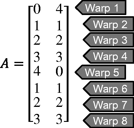
The derivation of a weave matrix according to Lomov/Gusakov is based on the definition of a reference system within the fabric unit cell. Here, the layers containing the warp yarns within a weft column are numbered from top to bottom, beginning with 0. Warp yarns are numbered as well, and their path within the fabric is listed line by line in the weave matrix. Warp yarn 1 (Figure 15) runs in layer 0 in the first weft column and switches to layer 4 in the next column, thus locking the rest of the fabric with the bottom weft yarn. By applying this system to the remaining warp yarns, the entire weave matrix is created for the pattern. A weave matrix comprising 8 × 2 entries is sufficient to define the example pattern of Figure 13 (see matrix in Figure 16).
Fabric layers and weft positions. Matrix form according to Lomov/Gusakov.
Subsequently, the pattern plot can be derived from the weave matrix. In order to transmit the data to the control software of the weaving loom, further conversions are necessary. First, the weave matrix has to be transposed, so the lines are arranged in the warp direction, analogously to the pattern plot (step 1):


Moreover, the pattern plot is read from bottom to top by the machine control system. Therefore, the order of the transposed weave matrix lines needs to be exchanged by a reversal matrix T. The size of the reversal matrix is 
A new weave matrix C appears as the interim result of the first conversion (step 2), and its data can now be read for the derivation of the pattern plot:

For this purpose, column vectors 
Resulting column vectors for different values of

Finally, the weave matrix B is generated by means of the selected data (step 4). This matrix is composed of the elements of column vectors 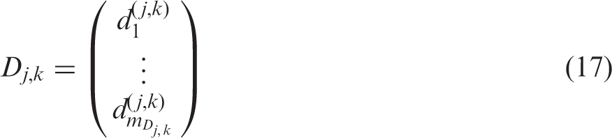
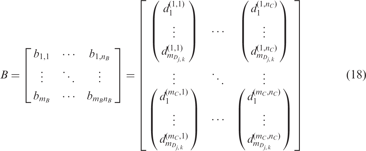
Hence, the number of rows mBof the resulting pattern plot corresponds to the product of number of weft columns and the maximum number of elements in the new weave matrix C. The number of columns of the pattern plot is equivalent to the number of coded warp yarns nC:


Applied to the example pattern, the weave matrix according to Lomov/Gusakov can be transformed into a conventional, machine-readable representation of a pattern plot. The new weave matrix C for the weave pattern presented in Figure 13 is as follows:

This matrix indicates the column vectors for the description of warp yarn lifts per weft insertion:

Finally, the matrix of the pattern plot is composed of column vectors, which corresponds to the draft in Figure 12:

The presented algorithm is applicable to arbitrarily defined complex weave patterns. Moreover, the criteria outlined in “Technological framework” section are fulfilled so that this method can be used without restrictions for the derivation of a pattern control system for the new shedding unit. Providing the proof of concept (“New shedding method and processed samples” section), the algorithm is applied to convert the sample bindings (Figures 6 and 7) into pattern plots as input for the jacquard controller. The general procedure and essential relations are summarized in Figure 17.
Algorithm for weave matrix conversion.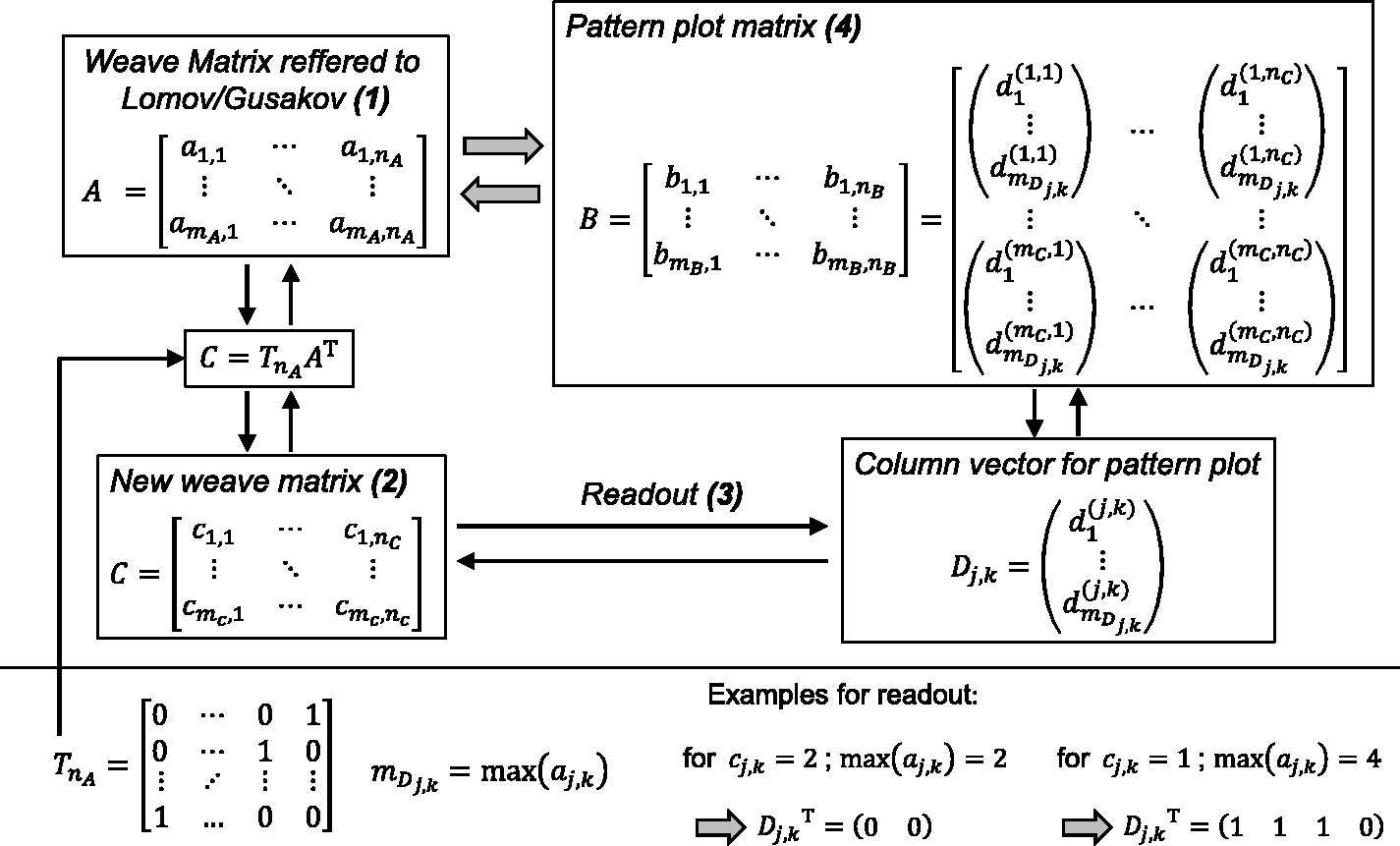
Conclusion
In this paper, a new approach to improve the weaving process of 3D multilayered woven fabric has been introduced. It bases on a novel special shedding method by using double flat steel heddles which allow an advantageous warp yarn arrangement within the shedding. Thereby the main problem of producing 3D multilayered fabrics as such as friction and clamping effects can be effectively solved which results in a high process stability and fabric quality. Furthermore, the method is suitable for the conventional weaving looms and their equipment periphery with a minimum effort of machine modification.
However, the flawless application of the new method requires the consideration of the complex interaction between the warp yarns and heddles and consequently the shedding sequence as well as the weave binding or rather the used underlying pattern plot. Initially, the interactions and requirements have been described in detail, and the basic restrictions have been formulated mathematically.
Furthermore, a suitable algorithm for weave pattern conversion is developed. The algorithm bases on matrix calculations and is completely software suitable. This enables the efficient transformation of the desired 3D woven structure into machine code. The quantitative assessment of the yarn impairment by the weaving process and comparison to conventional shedding methods will be part of a future publication.
Footnotes
Acknowledgements
This article presents selected results of the project DFG CH 174-42-1 “Pressure actuated cellular structures.”
Declaration of conflicting interests
The author(s) declared no potential conflicts of interest with respect to the research, authorship, and/or publication of this article.
Funding
The author(s) disclosed receipt of the following financial support for the research, authorship, and/or publication of this article: The authors would like to thank the Deutsche Forschungsgemeinschaft (DFG) for the financial support for the project at the Technische Universitt Dresden.