
Abstract
This paper details about the manufacturability of integrally woven ‘T’ stiffeners using orthogonal weaving technology based on the pleat formation concept. The development was carried out on a customized automatic take-up-at-will rapier weaving machine equipped with multi-beam warp let-off and electronic dobby. Bridging the gap between the base portions of the flange sections and locking the web sections together by using equally spaced intermittent extra warp yarns were the added innovations in the work apart from integral weaving of the ‘T’ stiffener. These innovations were achieved by suitably modifying the weave design. The development comprised a 5-part weave design for the ‘T’ stiffener and was carried out using 6K carbon tows. Calculations for X, Y, Z contents and overall fibre content by volume, from first principles of cloth construction approaches, for the flange and web sections of the ‘T’ profile, have also been included.
Keywords
Introduction
The most popular of the 3D reinforcement technologies for use in composites has been the noobing, also termed as the orthogonal weaving. The simplest explanation for orthogonal weaving is that non-interlaced yarns are orthogonally positioned in the X, Y and Z directions bound only at the ends. 3D orthogonal preforms and composites have been the subject of intensive research for various reasons. This is mainly due to the ease of manufacture of these preforms on the existing 2D weaving machinery (using the concept of pseudo sheds for thin preforms) as well as the relatively simpler modifications that need to be carried out on the machinery front to prevent unnecessary lifting and lowering of various warp sheets to create pseudo sheds. The technical textile industry adopts one of the above two approaches to develop orthogonal preforms, although the latter is the preferred option to prevent unnecessary warp damage. Literature reports on orthogonal preforms and composites are shear strength studies on carbon–carbon composites [1], studies of fibre architecture influence on tensile, compressive and flexural behavior [2], weaving damage studies [3], impact response [4], static and bending fatigue properties [5] and such others.
Manufacturing information in literature based on 3D orthogonal technologies include woven ‘Pi’ joint element for wind mill blade’s shear web and spar cap [6], simple noobed woven preform based on the conventional weaving approach [7], formability studies on complex moulds [8], studies of adhesive bonded joints of composites panel reinforced with non-crimp 3D orthogonal woven E glass fibre fabrics [9], design and manufacture of 3D flat woven fabric on an ordinary loom [10], effect of wire space and weaving pattern on performance of microstrip antennas [11] varied weave architectures [12], weaving of 3D orthogonal ramie fabric [13], development of UHMWPE/vinyl ester composites [14], PMR type polyimide composites using glass fibre preforms [15] and such others. Continuing on the approaches adopted for the manufacturing of the ‘T’ stiffener element in particular, attempts have been made to combine orthogonal flat preforms with stitching [16], design of a light weight ‘T’ joint [17], ‘flattening-weaving-unfurling approach [18], use of transverse stitching, z-Pinning and tufting technologies [19–23], use of PP layers [24], use of inserts [25], self-healing concepts [26] and others. With this backdrop, this paper adopts yet another approach for manufacturing the ‘T’ stiffener using orthogonal weaving approach based on the existing pleat concept [27]. As part of additional innovations in the work, to obtain structural continuity, the gap between the base portions of the flange sections has been bridged by weaving. The web sections are locked together by using equally spaced intermittent extra warp yarns which have been included in the development by making suitable changes in the weave design. The calculations for X, Y, Z contents in the web and flange portions as well as the fibre content by volume has been detailed in the paper.
Development details
Figure 1 shows the dimensions (in mm) of the ‘T’ structure that was contemplated to be woven. Figure 2 shows the step-by-step approach adopted for the integral weaving of orthogonal 3D ‘T’ stiffeners based on pleat weaving concept [28]. The base design comprised five parts as depicted in Figure 3. As shown in Figure 3, X1 is the stuffer warp used as X direction threads, X2 is portion of the binder warp in the X direction. Although this is part of the Z warp thread, in a typical ideal construction, this portion of the binder warp runs in the X direction with the possibility of contributing to the properties in that direction. Also the possibility of increasing its length over several picks exists, and hence it has been rationally decided to add on the X2 content to the X portion. Y is the weft thread in the Y direction and Z is the portion of the binder warp in Z direction. It is to be noted that Figure 2 is a pictorial step-by-step approach to develop the ‘T’ stiffener preform of Figure 3.
Dimensions of the ‘T’ preform (in mm). Concept of 3D integral ‘T’ stiffener development based on orthogonal weaving approach and the concept of pleat formation. Weft cross-section for five-part base weave design used for the development of integral 3D ‘T’ section (X1 – stuffer warp used as X direction threads, X2 – binder warp used as portions of X direction threads, Y – wefts in Y direction, Z – binder warp in Z direction).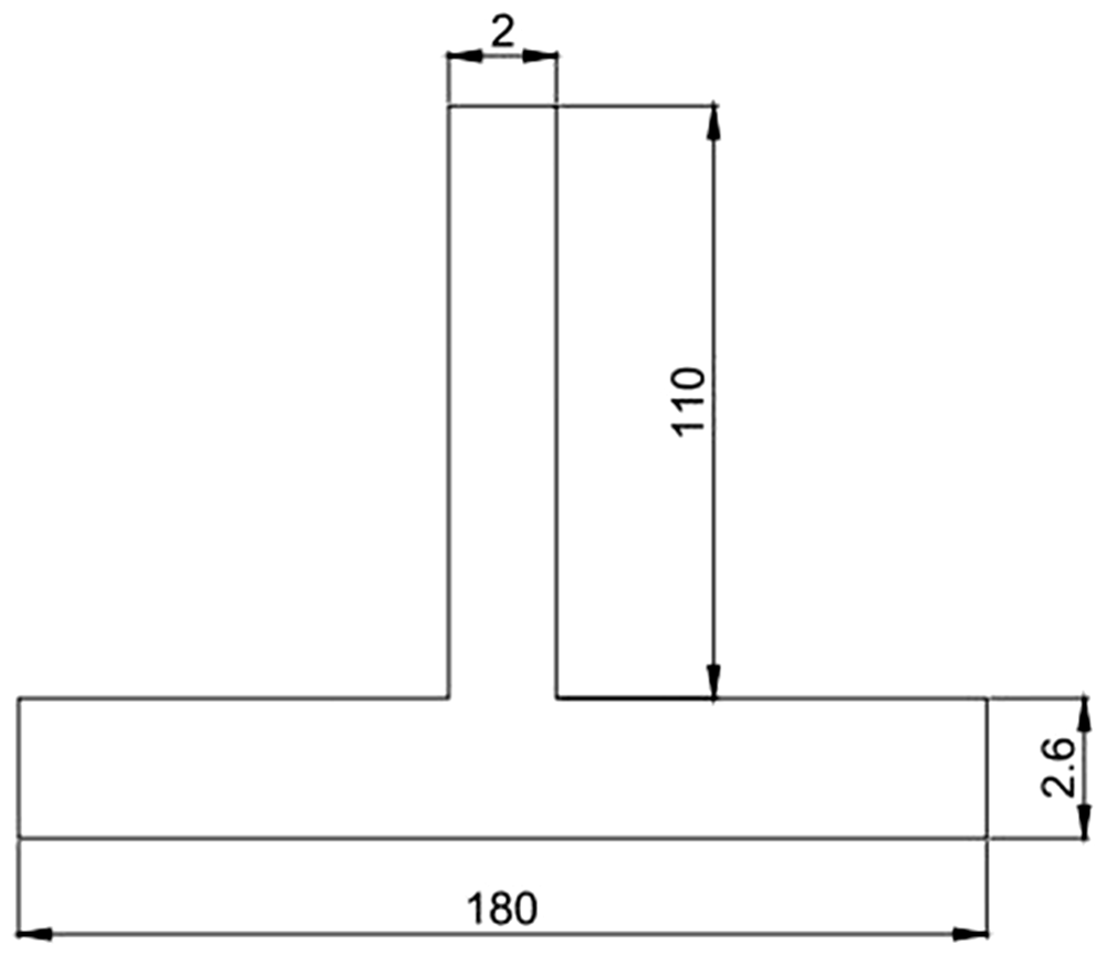


The five-part weave design was required as different sections of the ‘T’ profile had different weave architectures. Part 2 and part 4 of the weave design addressed the bridging of the flange sections.
For locking the web sections together, equally spaced intermittent extra warp yarns were introduced in the structure along the weaving width of the stiffener. These extra warp yarns were passed through separate heald shafts. The entry point, locking portion and exit point for the extra warp yarns were judiciously decided to demonstrate the proof-of-concept. Each set of extra warp yarns incorporated calls for design change of the flange and web portions and was planned prior to the development with regard to the stations and quantum. Figures 4 and 5 show the weave design for the ‘T’ profile with single and multiple extra warp yarns for bridging the gap in the web (variant 1 and variant 2). During weaving, the extra warp yarns were drawn from a separate beam due to the differing tensioning requirements. As shown in Figure 4, the changes in weave design as compared to Figure 3 has been denoted as 1a, 1b, 3a, 3b, 3c, 5a and 5b.
Weave design for integral ‘T’ with extra warp. (refer appendix 2 for detailed weave design) • Part 1a – Extra warp floating on top of the flange portion • Part 1b – Extra warp interwoven with the flange portion • Part 2 – Flange bridging portion • Part 3a – Extra warp woven with the web initial portion • Part 3b – Extra warp floating below the web portion • Part 3c – Extra warp woven with the web end portion • Part 4 – Flange bridging portion • Part 5a – Extra warp interwoven with the flange portion • Part 5b – Extra warp floating on top of the flange portion. Variant 2 – extra warp yarns to bind the web sections together with intermittent multiple extra warp yarns.

The loom used for the development was a customized automatic take-up-at-will rapier weaving machine equipped with multi-beam warp let-off and electronic dobby [24].
The material and weaving details used for the development are as below:
Material: Aerospace grade Carbon TC 33, 6K tows. Preform width: 300 mm. Details of warp layers: 4 (stuffer) + 4 (binder yarns) + extra warp layer. Reed count: 16’s Stock port. Denting order: Stuffer and binder in successive dents. Total number of beams: 5 (two for stuffer, two for binder yarns as they take different paths in the weave architecture and 1 for extra warp). Number of heald shafts used: 10 (8 for orthogonal T and 2 for extra warp yarns).
Weaving details
Preparatory process
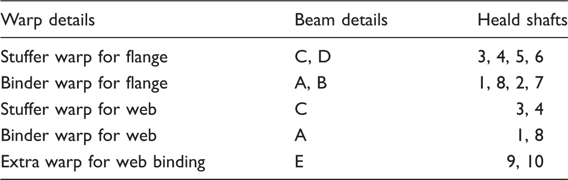
The preparatory process comprised carrying out the regular activities as required during conventional weaving. In addition to this, the distribution of warp yarns onto different beams was carried out as shown in Figure 6. It is to be noted that Figure 6 shows the arrangement of beams as provided by the manufacturer and the current weave design has utilized five beams (beams A to E). This was required to accommodate the different tensioning requirements and the yarn paths the particular set of warp would take during weaving. Table 1 shows the warp yarn distribution with respect to the beams and heald shafts. During the weaving of the web portion, few of the stuffer warps of the flange portion are woven into it, while the other stuffer warps continue unwoven under the web. Since the formation of the web calls for increased length of the stuffer warp, these are drawn from a separate beam C. The stuffer warps not woven into the web portion are drawn from the beam D. This is done to address the length variations of the stuffer warps. In such case, if the weaving is a plain 3D fabric, a single beam would suffice to carry all the stuffer warps. Similar analogy applies to the binder threads of the flange and web portions (binder threads on beam A are for the web portion).
Beam arrangement for warping (A, B faces the loom). Warp yarn distribution for weaving.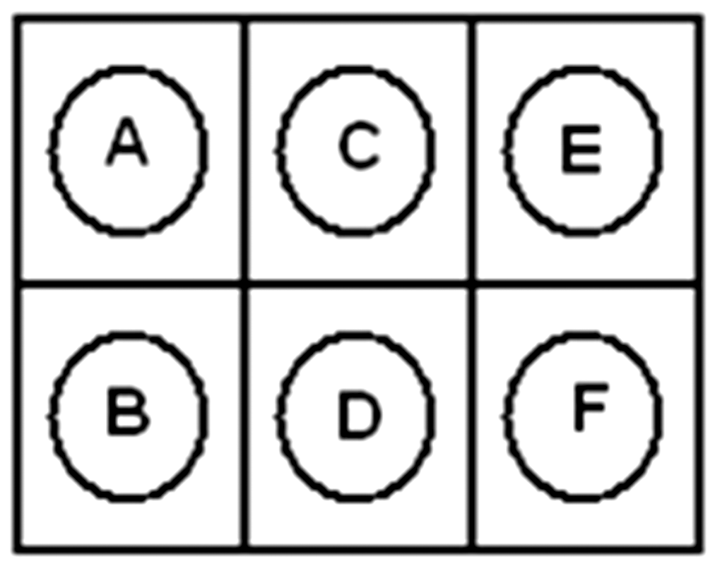
The warp beams were prepared using a single-end warping machine and leasing was provided to enable ease of drawing-in. The prepared beams were mounted on to the beam stand and drawing-in was carried out as per the regular process based on the weave design. Figure 7 shows the photograph of the beaming process.
Beaming of carbon tows on single-end warping machine.
Weaving
Based on the weave design, weaving was carried out as per normal conventions. The additional steps and the differences compared to conventional weaving were as below:
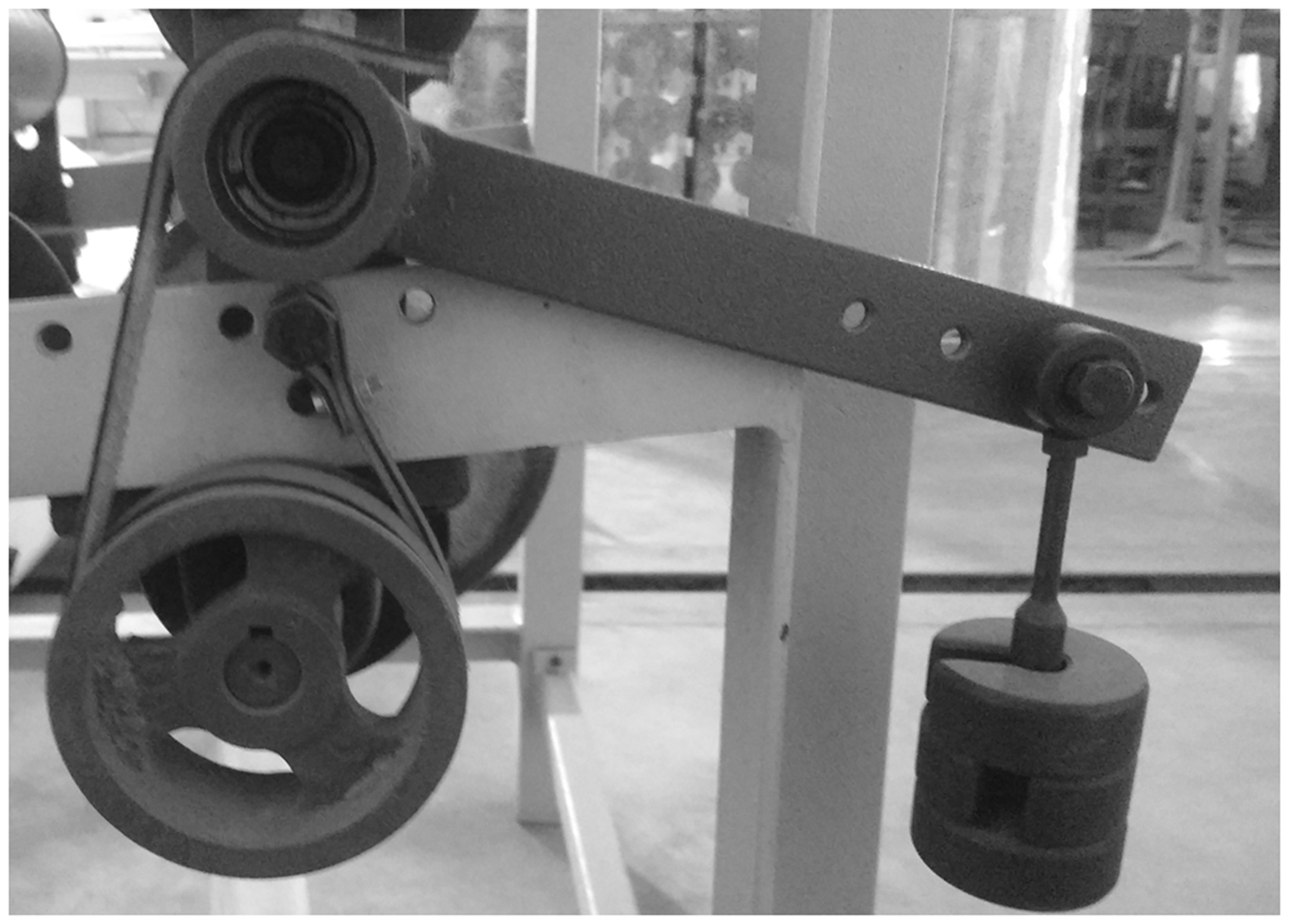
Weave design was different in different sections (part 1 to part 5) as detailed in Figure 3 Take-up-at-will was required to be carried out as per the requirements of the specific portion of the preform. For the flange portion, take-up was for every fifth pick and for the web portion take-up was for every second pick. The software on the loom provides option to define the take-up for every pick. For flange weaving, the software was fed with take up as 0 for the first four picks, where the take-up system remains stationary for these picks. For the fifth pick, the take-up was fed with a value of 1 at which point, depending on the set pick density the take-up roller would move forward to that extent. Similarly, for web portion, the take-up for first pick was fed as 0 and for second pick as 1. This concept of take-up-at-will enables continuous weaving with any variations in the preform and thus is amenable for production purposes. The weaving sequence adopted was as follows: weaving of the flange portion followed by weaving of the web portion and then terminated with weaving the flange portion again. The entry and exit of the extra warp yarns to bind the web portions of the ‘T’ stiffener was carried out at the appropriate juncture during weaving. To retain integrity of the 3D T, the entry of the extra warp need to be at least four to five picks ahead of the web forming point and woven into the structure (preferably plain). The further away from the juncture the better, so as to have a firm grip. The same analogy applies for its exit. At the termination point of weaving of the web, take-up reversal was executed in tandem with winding of the unwoven warp back onto the beam till such point as the fell of the previously woven flange abets the reed in front centre. Tension adjustments of all the beams, especially the extra warp beams were correspondingly carried out to obtain a stable integral ‘T’ preform. The loom has a negative let-off with self weighted tensioning system for the beams (Figure 8). As can be seen in Figure 8, it has provision to add weights based on the specific tension requirements. Lifting of the weighted handle enables beam reversals. The reversal of the take-up beam is software controlled and rewinding onto the beam is done by lifting the handle and rotating the beam manually and this is done inch by inch. Flange weaving was continued as per the design to the required length. During production, it is to be noted that the take-up of the preform will be linear, since the successive T formation will not allow winding or folding to preserve the architecture. Negative let-off with self-weighted tensioning system.
The flange weaving was done with the base design (part 1) till the length reached was 90 mm. Then one repeat of the first half of the bridging junction (part 2) was woven followed by web weaving (part 3). On completion of weaving web portion of 220 mm, the formation of ‘T’ was achieved by the reversal of take-up. This was done inch by inch, i.e. reversing the take-up roller by 1 in. followed by equivalent beam reversals (beams B, D and E) as explained previously. This was continued as shown in Figure 9(a) to (d). The next half of the bridging junction (part 4) was woven (one repeat). One ‘T’ formation was completed by weaving the remaining length (90 mm) of the flange (part 5). Formation of T and further weaving of flange potion are shown in Figure 9(e). Figure 10(a to e) provides the part wise weave design details for weaving the integral ‘T’ stiffener with bridged flange and web portions. Table 2 provides the preform details and Appendix 1 provides the calculation details for the X, Y and Z contents of the developed ‘T’ section derived logically from first principles of cloth construction. Appendix 2 provides the details of the weave design for the variant 1 of the T formed with extra warp yarn.
Formation of integral ‘T’ stiffener using take-up reversal approach and simultaneous winding of warp beams. Figures a–e show the incremental formation of the T loop. Weave design for integral ‘T' – refer figure 3 also (a to e represents Part I to Part V respectively). Specifications of the woven ‘T’ preforms.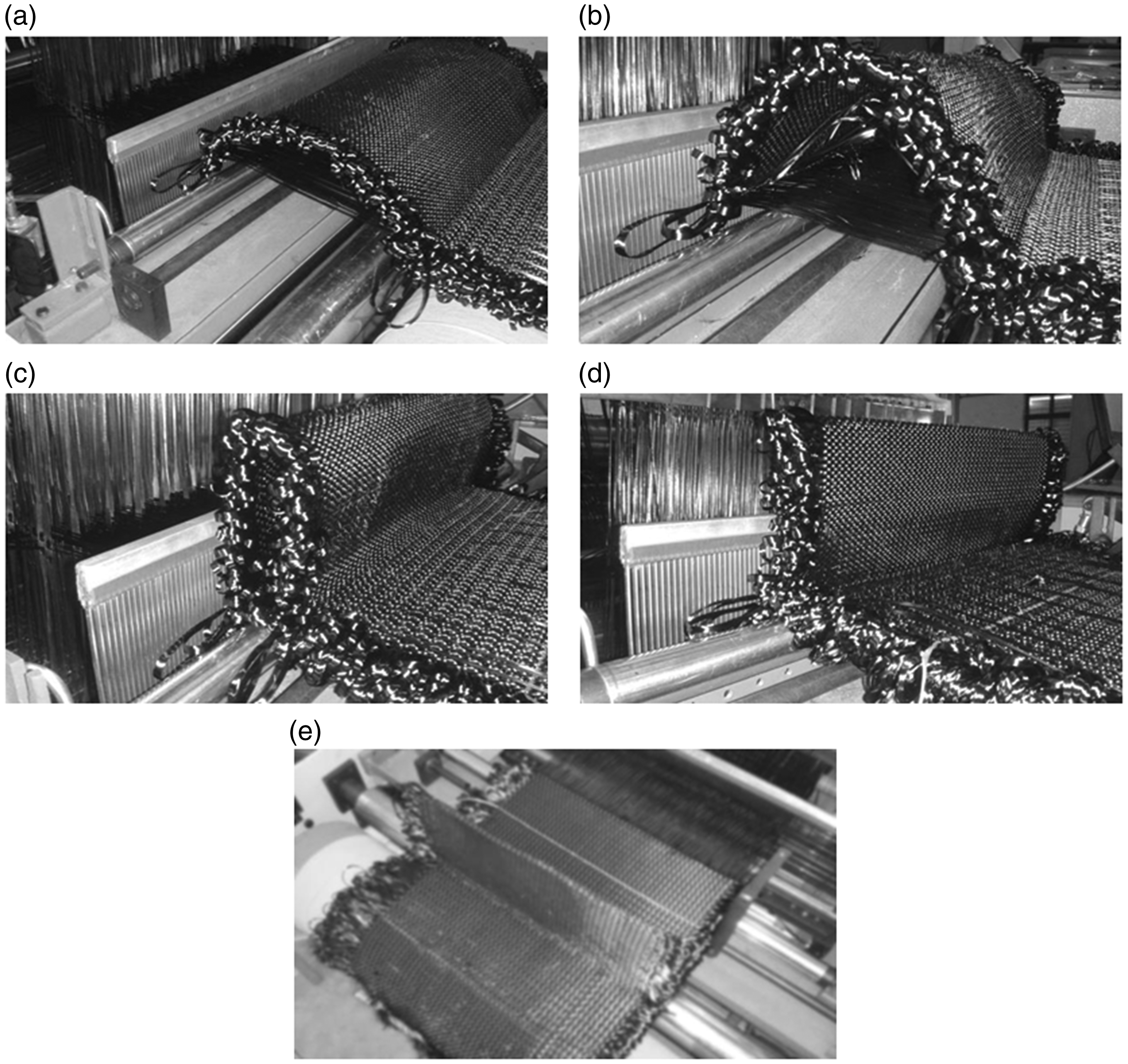


Figure 11 shows the multiple number of ‘T’ stiffener integrals developed using the pleat weaving concept as described above. It is possible that the scope for further tailoring the X, Y, Z fibre contents exists by varying the weave architecture and the use of different count yarns.
Photograph of the integral ‘T’ stiffener developed based on the pleat weaving concept.
Conclusions
3D orthogonal ‘T’ preform was developed on a customized automatic take-up-at-will rapier weaving machine equipped with multi-beam warp let-off and electronic dobby. The work involved building the flange, branching off of a portion of the flange to build the web, forming the ‘T’ loop with simultaneous reversal of flange warp yarns onto respective beams and continuing the development of flange portion to the required final dimensions of the ‘T’ preform. As part of innovations in the development bridging, the gap between the base portions of the flange sections and locking the web sections together by using equally spaced intermittent extra warp yarns was carried out. Calculations for X, Y, Z and fibre content by volume have been put forth. This work has thus demonstrated the feasibility of integral weaving of 3D ‘T’ stiffener based on orthogonal weaving technology and the pleat weaving concept.
Footnotes
Acknowledgements
The authors wish to thank the Director, NAL, Head CSMST, Mr. Ramaswamy Setty and Mr. Kamalakannan GM for their support. One of the authors, Sandeep, thanks CSIR for providing the SRF to carry out the work.
Declaration of Conflicting Interests
The author(s) declared no potential conflicts of interest with respect to the research, authorship, and/or publication of this article.
Funding
The author(s) received no financial support for the research, authorship, and/or publication of this article.