
Abstract
Mechanical, physical and electrochemical characteristics are one of the important properties of ion exchange membranes. These parameters are required for a next operation and for an application in an electrodialysis (as tightness of a stack, energy consumption, capacity of electrodialysis). The goal of this article is comparison of the influence of the different reinforcing fabric on the properties of ion exchange membranes. Six types of ion exchange membranes with the nonwoven fabric, the monofilament knit, the multifilament knit, the monofilament woven fabric, the multifilament woven fabric, and for comparison non-reinforcing ion exchange membranes were chosen. The most important properties of a fabric in this application are thickness, free area related to the warp and the weft, mechanical strength, the material (shrinkage), type of fabric (plain or twill weave, a knit, monofilament, multifilament) and of course price. Electrochemical, physical and mechanical properties of ion exchange membranes were studied. Non-reinforcing ion exchange membranes have lower mechanical strength, but the best elongation. These ion exchange membranes report big relative dimension changes after swelling in demineralized water and the lowest value of the areal resistance. The most appropriate ion exchange membrane is with woven fabric from monofilaments after comparison with other ion exchange membranes in terms of the quality of the lamination and other electrochemical, physical and mechanical parameters.
Introduction
Coated fabrics were used since the 18th century, when the fabric was soaked in the linseed oil to produce waterproof cloth. Since then coated fabrics have been extensively used for a variety of applications and created composite materials. The most widely used fabrics were coated on one or both sides of a polymer. Properties of the resulting layers are dependent on many parameters, such as the types of bonding fabric, the fibre density in the fabric sett or orientation. Other important parameters of fabrics are good mechanical properties (elongation, modulus, strength), fibre type, dimensional stability, adhesion, absorption of the polymer matrix and the fabric, temperature resistance and the homogeneity of the fabric [1, 2].
The influence of the parameters of fibres, material or a type of threads interlacing on the resulting properties of fabrics is studied by many authors [3–6]. The stability of threads interlacing means a shift of individual threads from their positions, in the case of woven fabrics it occurs, e.g. to slope towards the warp and weft threads or deformation of the mesh. For the knitted fabrics, it usually occurs in displacement of threads in a weft. In the case of the nonwoven fabric it is more of a local displacement of the threads where the threads do not have been thermally interconnected.
Heterogeneous ion exchange membranes (IEMs) are also layered systems. They contain a polymer matrix and an ion exchange resin having ion exchange function groups. IEMs can be reinforced with the reinforcing fabric. IEMs are separation membranes which separate cations and anions from the solution if electric field is applied. Thanks to the fact that the IEM contains fixed ionic functional groups, free counter ions can be transported through IEMs but transport of co-ions is limited [7–9]. Figure 1 shows the scheme and the simple principle of IEMs. The IEM can be the anion exchange membrane (AEM) or the cation exchange membrane (CEM) depending on the counter ion which can be transported through the IEM.
Scheme of structure and simple principle of IEMs. IEMs: ion exchange membranes.
IEMs can be used for electrodialysis (ED) [8, 10–15], electrodeionization (EDI) [16–19], membrane electrolysis, diffusion dialysis (DD), electrophoresis (EF) [20–22] or in power sources as fuel cells [23–25]. IEMs are the most frequently utilized in the desalination of brackish and surface water, purification of waste water, water desalination after tertiary biological treatment, purification of organic substances, stabilization of wine, demineralization of whey, separation of inorganic and organic solutions and purification of organic substances.
All commercial, competitive IEMs are laminated. Competitive company (Shchekinoazot) as well as Chinese manufacturers (Shanghai Shangua, Zhejiang Qiunqiu) commonly uses a woven fabric with the plain weave from monofilaments for lamination of the heterogeneous IEMs. Homogeneous IEMs that are produced by other techniques are usually laminated with a nonwoven fabric or a woven fabric from multifilament (Fujifilm, GE, DuPont, Ionics, Astom Co.). Non-reinforcing IEMs are brittle in the dry state, and should be handled with caution. After swelling IEMs are more flexible, but still they are much more prone to rupture and destruction than reinforcing IEMs [26–29]. A major problem is to seal the ED stack to prevent leakage of solution out of ED stack or mixing diluate and concentrate solution inside the ED stack. For this reason, non-reinforcing IEMs were laminated using the several types of fabrics.
The goal of this article is comparison of the influence of different reinforcing fabrics on the properties of IEMs. From the above, it follows that manufacturers of IEMs use different fabrics to reinforce IEMs. However, it has not yet been reported how the use of the individual reinforcing fabric will be reflected in the desirable properties of IEMs. Optimization of the reinforcing fabric is essential for manufacturers of IEMs in terms of electrochemical, mechanical and physical properties.
Experimental
Preparation of IEMs
Only CEM was chosen for better orientation in the results and to compare the influence of the reinforcing fabric. The reinforcing fabric has the same effect for both membranes (CEM, AEM). There would be unnecessary duplication of results.
Preparation of CEMs and used materials was described in the literature [30]. CEMs were prepared in several processing steps. Initially, ion exchange resin particles (Purolite C, Amberjet Dow Chemicals) were dried in an industrial dryer to a moisture content not exceeding 2% and powdered in a vibratory mill (Vibrom) at 25℃ to the desired particle size distribution (median 10–15 µm). Powdered ion exchange resin was mixed with polyethylene matrix (metallocene polyethylene, Exxonmobile Chemicals) in HAAKE PolyLab OS (Rheomex, Thermo Scientific) into the form of the granulate with size about 5 mm. Homogenizing twin screw speed was kept constant at 60 r/min, temperatures of zones were profiled from 125℃ to 140℃. Prepared granulates were extruded into membrane foil (CEM) with the same conditions (single screw speed 60 r/min, temperatures of zones profiled from 125℃ to 140℃) but a single screw extruder with the die (the opening of the slit 0.6 mm, the width of the die 10 cm) was used. For further definition of membrane thickness and defined cooling, a three-roller was used. Pictures of the extruders, extrusion heads, the granulates and membranes are shown in Supplementary materials (Supplementary Figure S1). The three-roller with screw-defined pressure is not suitable for the simultaneous extrusion and lamination of the reinforcing fabric, and it is necessary to subsequently laminate the CEMs samples by the hydraulic press. The last processing step, hot pressing and lamination (hydraulic press ZHOT, Presshydraulika, 135℃, 10 min/25 bars and cooling to 65℃), was used to ensure the homogeneity properties of CEMs. Two-sided lamination is used when pressing the samples’ CEMs, i.e. two fabrics are used for the preparation of each piece CEMs from an extruded membrane foil. So, the thickness of IEMs was taken by two fabrics and non-reinforcing IEMs. Part of the material is compressed in the hydraulic pressing; therefore, thickness of IEMs was not determined by sum of the components. Minimum thickness of the prepared IEMs is treble of the used reinforcing fabric. So, the thinner the reinforcing fabric is, the smaller the resulting IEM is [26].
Characterization and parameters of reinforcing fabrics
Properties of used reinforcing fabrics Zora, Wora, Ulester, Uzel and Novolin.

aNumber of threads of reinforcing fabric applied to 1 cm.
bShrinkage in the weft direction was determined at 160℃ for all fabrics except Novolin PP in which the temperature was only 120℃ according to EN ISO 80 0823.
cUltimate strain and force in warp/weft direction (MD/TD).
dDiameter of filament/thread for reinforcing fabric Zora, Uzel.

Tensile curves for the reinforcing fabrics (warp and weft direction, MD/TD). MD: machine direction; TD: transverse direction.

SEM for reinforcing fabric; (a) obverse side of Zora, (b) obverse and (c) reverse side of Wora, (d) nonwoven fabric Novolin, (e) Uzel and (f) Ulester 32S. SEM: scanning electron microscope.
The woven fabric Ulester and Uzel are formed by plain weave. For woven fabric Uzel the thread with 18 filaments and 800 turns was used. The nonwoven fabric Novolin is thermally bonded, spun-bond. Fabrics Zora and Wora are plain jersey fabric (warp knitwear) – type Marquisette. Zora is formed by multifilaments with 20 filaments. The scheme of the interlacing threads is shown in Figure 4.
Schemes of threads interlacing for (a) knitted fabric Wora, Zora – Marquisette, and (b) plain weave of woven fabrics Ulester, Uzel.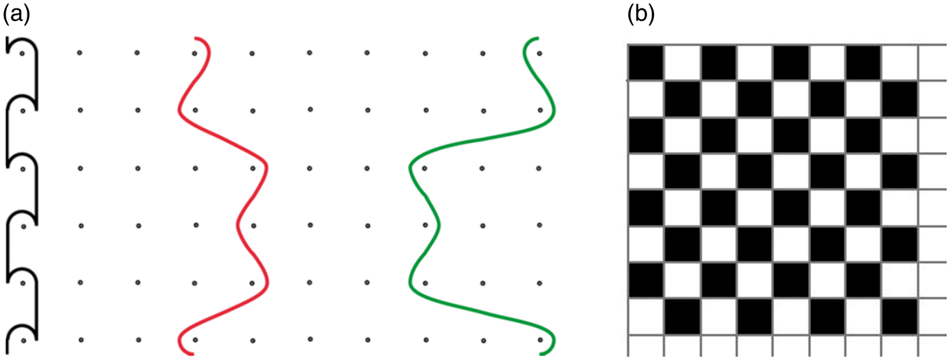
The mechanical properties of the reinforcing fabric were measured with samples of 50 mm × 200 mm dimensions (clamping length) according to the EN ISO 13934-1 standard using an H5KT (Tinius Olsen) tensile testing machine with a speed of 100 mm min−1. The direction stress was in the warp and weft direction (machine direction [MD]/transverse direction [TD]). The standard deviation of this method and individual measurements is listed in Supplementary materials.
Shrinkage in the weft direction was determined at 160℃ for all fabrics except Novolin in which the temperature was only 120℃ according to EN ISO 80 0823.
The structure of the reinforcing fabrics (and then also CEMs) was investigated using a FEI Quanta 250 FEG SEM. The conditions for measurement under SEM were 5 kV voltage, high vacuum (4.5 x 10⁻³ Pa pressure) and Everhart Thornley detector (ETD) or in low vacuum (40 Pa) with large field detector (LFD) for secondary electrons. Samples of reinforcing fabrics were sputtered by 10 nm thick layer of chromium before measurement by the Quorum Technologies Q150T S/E/ES. An optical stereoscopic digital microscope DSTM 13 (Intracomicro) was used as a second microscope.
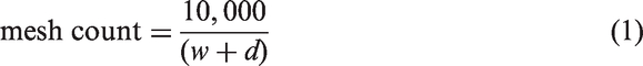
The image analysis was performed and parameters of the reinforcing fabric such as the diameter of filaments/thread (d, µm) and mesh opening (w, µm) were determined. It is possible from these parameters mesh count (warp/weft, 1 cm−1) and the open area (ao, %) are defined according to equation (1) and equation (2) [31, 32]

Schematic representation of the open area of the reinforcing fabric is shown in Figure 5.
Schematic representation of the open area (ao, %) of the reinforcing fabric; diameter of filaments/thread (d, µm), mesh opening (w, µm).
Characterization of IEMs
Electrochemical, physical and mechanical properties of IEMs compared to different reinforcing fabric were studied. Measurements of permselectivity, specific and areal resistivity, relative water content (rwc) with other physical properties (relative change of thickness, length and width after swelling in demineralized water) are published in the literature [30]. Mechanical properties are described by Stránská et al. [33].
Relative water content and other physical properties (relative change of thickness, length and width)
The rwc (%) and other physical properties (php, %) such as the relative change of thickness, length and width after swelling in demineralized water were determined in the following way. IEMs were dried in an oven (WTB Binder) at 75℃ (5 h) and 105℃ (1 h) to a constant weight and weighed in the dry form. Length, width and thickness were determined. Subsequently, the IEMs were swollen in demineralized water at 25℃ for 24 h and dabbed with filter paper to remove excess water. The weight, length, width and thickness of IEMs in the wet form were measured. Then the physical properties were determined by equation (3)

Error determination of rwc is given by the accuracy of the analytical balance, and is 0.5%.
Areal and specific resistance
IEMs for measuring resistance (areal resistance RA, Ω cm2 and specific resistance Rs, Ω cm) were swollen in demineralized water at 25℃. Then, they were conditioned in 1 mol dm−3 NaOH solution (p. a., 40 g mol−1, Penta, Czech Republic) and converted into the corresponding form using 1 mol dm−3 HCl solution (35 % p. a., 36.45 g mol−1, Penta, Czech Republic) in the subsequent step. The IEMs were equilibrated with 0.5 mol dm−3 NaCl (p. a., 58.44 g mol−1, lach:ner, Czech Republic) for 24 h. Electrochemical resistance was measured in 0.5 mol dm−3 NaCl solution at 25℃ in a special experimental cell (specially manufactured for MemBrain s.r.o.) using a compensation method. The experimental cell consisted of two parts separated from each other. The appropriate solution was mixed in an experimental cell. Electrochemical resistance was measured between reference electrodes (silver – silver chloride, RAE 111 – Ag/AgCl, Monokrystaly s.r.o.) and then constant direct current (I = 10 mA) was applied between platinum electrodes (electrodes series PPE, Monokrystaly s.r.o.). Electrochemical resistance was determined from two measurements of potential difference. The first measurement of potential was performed without the IEM (only solution, Usolution) and the second with the IEM (Usolution + IEM) between the two parts [34, 35]. The active area (S, cm2) of the IEM was 0.785 cm2. The thickness (th, cm) of the IEMs was determined using a micrometer. Specific and areal resistance were determined by equations (4) and (5). The standard deviation of this method and individual measurements is listed in Supplementary materials


Permselectivity
Permselectivity (P, %) of IEMs was determined by Henderson’s method in the same measuring cell as electrochemical resistance but with the following KCl solution (p. a., 74.56 g mol−1, Penta, Czech Republic) pair 0.1–0.5 mol dm−3 in separated parts and without applied direct current. Potential (Umeas.) was measured between reference electrodes (calomel RCE 101 – Hg/Hg2Cl2, Monokrystaly s.r.o.). The permselectivity is determined by equation (6).
The IEMs were equilibrated with 0.5 mol dm−3 KCl for 24 h before the measurement [36, 37]


Mechanical properties
The mechanical properties of IEMs were measured with samples of dimensions of 25 mm × 150 mm (clamping length) according to the EN ISO 527-3 standard using an H5KT (Tinius Olsen) tensile testing machine with a speed of 5 mm min−1. The direction stress was in the warp and weft direction (machine direction [MD]/transverse direction [TD]). The standard deviation of this method and individual measurements is listed in Supplementary materials.
Results and discussion
Dimensional changes of IEMs in water or other solution are one of important processes. The polymer matrix is stretched during the swelling. Different porous structure is created depending on the polymer matrix and its properties. More pores lead to increase the free volume in IEMs and decrease the mechanical properties. This behaviour influences all IEM properties like the resistance and the permselectivity [38]. Electrochemical resistance of IEMs strongly depends on ion mobility through the IEM. The higher the swelling changes and the higher the concentration of functional groups, the higher the ion mobility [38].
Mechanical (modulus, stress, and strain), physical (relative changes after swelling) and electrochemical (areal and specific resistance, permselectivity) properties of six types of CEMs.
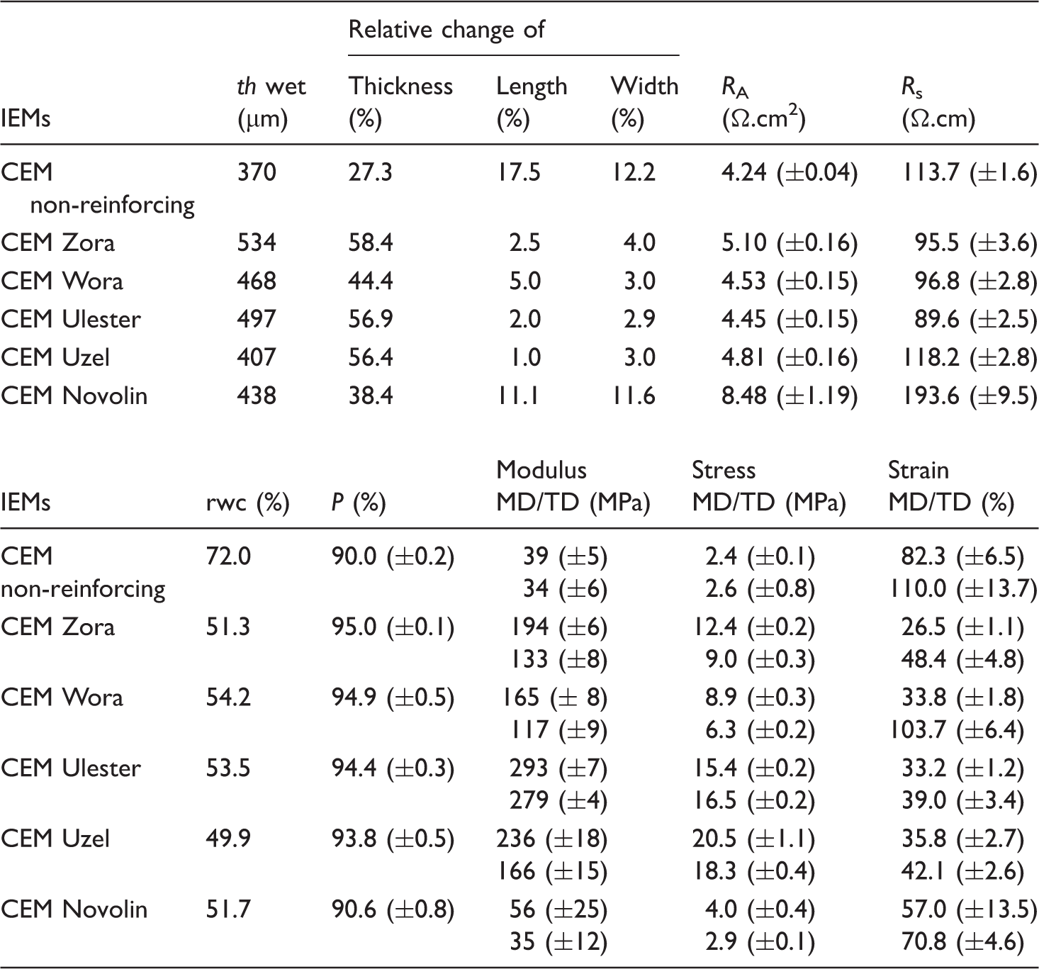
RA: areal resistance; Rs: specific resistance; th: thickness; rwc: relative water content; P: permselectivity; MD: machine direction; TD: transverse direction.
Changes of conductivity entail reductions of the performance of ED process, as the major part of the resistance in an ED stack is owed to the IEMs.
The non-reinforcing CEM and the CEM Uzel show low values of areal resistance but thickness of these CEMs is relatively small so the specific resistance which is not dependent on the thickness is higher than the other CEMs. CEM Ulester has the lowest specific resistance. Resistance of CEMs is dependent on many parameters of the reinforcing fabric. For example, it is the open area or thickness of fabric. Bigger value of open area of the reinforcing fabric ensures the lower areal resistance of the IEM [39]. The connection with the specific resistance cannot be found. But the bigger value of open area must not be at the expense of stability of threads interlacing. Stability of threads interlacing is important for the manufacture of IEM. During lamination of the reinforcing fabric to the IEM it must not lead to the deformation of the fabric, for example narrowing. The woven fabric Uzel has the smallest value of open area and in the opposite side it is the knit Wora but CEMs with these fabrics do not have significantly different electrochemical properties. If we re-focused on the relationship between the open area of the reinforcing fabric and the areal resistance of IEMs, we conclude that the non-reinforcing IEMs have the lowest the areal resistance [40]. The lamination of two reinforcing fabrics into one IEM also plays important role; it may not be a precise alignment of the individual threads in the reinforcing fabrics, and this leads to a further reduction in the open area in the IEM. This reduction is difficult to define and may cause further increase in the areal resistance in some samples.
The CEM Novolin has the biggest value of specific and areal resistance. The areal and the specific resistance of CEM are high due to the conditions of the lamination, where polypropylene is stable to about 120℃. The CEMs were laminated at 135℃. At this temperature, there is a partial degradation of the threads and in some places a continuous layer of polypropylene (foils) will be formed. The selective transport of ions across the CEMs is difficult and the CEMs exhibit the higher resistance. When the temperature of the lamination is lower, there would be no sufficient melting of the heterogeneous polymer matrix and the nonwoven fabric is not sufficiently laminated into the structure of the CEM. After swelling, there is a complete separation of the reinforcing fabric from the membrane foil.
Resistance of CEMs is dependent on the thickness of the reinforcing fabric. The specific resistance is equal to the areal resistance based on the thickness, i.e. the thinner the IEM is, the greater the intended area is for the same volume. Thanks to this, the specific resistance of the IEM increased significantly for the non-reinforcing IEM, although the areal resistance of the IEM was the lowest.
The effect of the monofilament or multifilament reinforcing fabric is only apparent from the areal resistances. CEMs with multifilament reinforcing fabric exhibit higher areal resistances. Due to different CEMs’ thicknesses, the specific resistances report comparable values. As shown below (Figure 7), reinforcing fabric with multifilament is harder to laminate into the membrane polymer matrix. Pores and microchannels should be created along the reinforcing fabrics to facilitate the transport of ions and decrease in the areal and the specific resistance. The problem is, however, that the used reinforcing fabrics have different open area and thicknesses and therefore the influence of the fibre type overlaps with other influences.
The type of the reinforcing fabric has the influence on the relative change of thickness, length, width and rwc (water uptake). rwc for reinforcing CEM is about 50–55% but non-reinforcing CEM swells by more than 70%. CEMs with woven fabrics and knits have the bigger relative change of thickness after swelling compared to relative change of length and width. For the non-reinforcing CEM and CEM Novolin the reverse trend applies. Stable physical properties of CEMs are very important for used CEMs in a specific ED application. Due to the high dimensional changes of CEMs the tightness of ED unit may be reduced; the plugged inlets of the solution which in turn may stop the ED process.
The mechanical properties of IEMs correlate to behaviour of polymers in highly filled composites. Tensile curves for CEMs are shown in Figure 6. In Supplementary material (Figure S2), the combined graph for reinforcing fabrics (Figure 2) and CEMs (Figure 6) are inserted. Due to the different methodology and used measured parameters, it is not possible to identify the results, but the same trend curves are visible. Non-reinforcing CEMs have very low mechanical strength, but protracting their structure is not a problem. This is because in the structure any reinforcing fabric is not present which causes increase of mechanical strength and it does not allow so high elongation of the polymeric structure.
Tensile curves for CEMs (warp and weft direction, MD/TD). CEMs: cation exchange membranes; MD: machine direction; TD: transverse direction. Quality of lamination of CEMs; (a) CEM Ulester, (b) CEM Novolin, (c) CEM Uzel and (d) CEM Zora. CEM: cation exchange membrane.

High value of elongation is not so important for final use of CEMs. The mechanical strength is not improved using the nonwoven fabric Novolin, moreover CEMs Novolin have a lower percentage of elongation than the non-reinforcing CEMs. The knits have distinctly bigger value of elongation and lower value of strength in the weft direction than in the warp direction that it is due to manufacture of the knit. These trends are same for the CEM Zora and the CEM Wora. The woven fabrics Ulester and Uzel have the similar value of elongation and stress in both direction and the same trend applies for CEMs. Using woven fabrics or knits improves the mechanical strength and durability. These parameters are important for next application of CEMs in ED process.
Table 2 shows that the Young modulus, which can be related to the rigidity of a material, varies when using different fabrics. Non-reinforcing CEM and CEM Novolin have the lowest values of modulus. The highest values of modulus are for CEM Ulester and CEM Uzel in the warp direction. The higher the Young’s modulus the lower the deformation of material. This finding is important for folding and sealing of ED stack to prevent leakage of processed solutions (concentrate and diluate).
The quality of the lamination incorporating the fabric into the polymer binder is so important for the application of IEMs in the ED. The quality of lamination is shown in Figure 7. The binding points are evident only on the surface of the CEM Ulester; other CEMs with Uzel, Zora or Novolin have worse quality of lamination. because the reinforcing fabrics are composed of multifilament. For the CEM Novolin it is caused by heterogeneity of fibres in the structure of non-woven fabrics. Thickness of Novolin is around 100–110 µm, which is not constant.
The quality of lamination depends on the type of the fabric used. The heterogeneous blend of polyethylene with the ion exchange particles is sufficiently viscous to fill all the multifilaments of the fabric. In case of the monofilaments opposite situation occurs. The heterogeneous blend wraps the monofilaments.
Conclusions
Two woven fabrics Ulester and Uzel, two knits Zora and Wora, and the nonwoven fabric Novolin were used as reinforcing fabric in CEMs. CEMs have different parameters which relate to parameters of the reinforcing fabric. The goal of this article was to compare the electrochemical, physical and mechanical properties of CEMs with different reinforcing fabric.
Non-reinforcing CEMs have lower mechanical strength, but the best elongation. These CEMs have big change in relative dimension after swelling in demineralized water. Areal resistance of these CEMs is the best. CEMs with woven fabrics Ulester, Uzel and knits Wora and Zora have good mechanical durability and lower changes in swelling dimension. But using the fabric, the areal resistance increases which has influence on the flow solution in the ED stack. The cheapest variant of CEMs is the CEM with nonwoven fabric Novolin; any reinforcing fabric should not be used because nonwoven fabric increases the resistance. Nonwoven fabric Novolin decreases the dimensional changes but mechanical durability of CEMs is still lower. Based on the quality of lamination and electrochemical, physical and mechanical parameters CEM is the best membrane with the woven fabric from monofilaments Ulester compared with other CEMs.
Footnotes
Declaration of Conflicting Interests
The author(s) declared no potential conflicts of interest with respect to the research, authorship, and/or publication of this article.
Funding
The author(s) disclosed receipt of the following financial support for the research, authorship, and/or publication of this article: the framework of the project No. LO1418 “Progressive development of Membrane Innovation Centre” supported by the program NPU I Ministry of Education Youth and Sports of the Czech Republic, using the infrastructure Membrane Innovation Centre.
Supplementary Material
Supplementary material is available for this article online.