
Abstract
In this study, for the first time, coating formulation based on milled carbon fibre has been applied on textile substrate to prepare flexible covering material for microwave protection. Cotton fabric with its inherent high dielectric property and finite length with close network of carbon milled fibre has synergised to generate highly conducting surface (σ = 96.22 S/m). The samples are prepared by coating of milled carbon fibre in various concentrations with polyurethane as binder on cotton fabric. Polyurethane contains hydroxyl and hexamethylene diisocynate groups which are polar under external electric field (dielectric constant 3.2–6.5) and also contribute high dielectric properties in coated fabric. Samples were evaluated for surface resistivity and microwave properties, i.e. permittivity, scattering parameters, reflection, transmission, absorption and reflection loss. Permittivity of high level (ɛ′: 21–31, ɛ″: 60–84) and attenuation of high order (α = 1971–2354 Np/m) are achieved. The sample coated with milled carbon fibre and polyurethane in ratio of 1: 1.67 on weight basis has shown 67–70% reflection, 28–30% absorption, 0.1–0.5% transmission, and EMI shielding of 28–30 dB in X (8.2–12.4 GHz) and Ku (12.4–8 GHz) frequency band. The results were further analysed theoretically and correlated with the scattering parameters and other microwave properties.
Keywords
Introduction
As the technology grows, use of miniaturised electrical and electronic systems has increased enormously in all the engineering and technology fields. The advances in electronics reduce the component size and placing more number of electrical/electronic parts in a very confined space which builds the problem of electromagnetic interference (EMI); this interferes within the system and with other systems through em wave radiation rendering malfunctioning to electronic equipments. EMI also offers navigational problem to ship and aircraft [1,2]. Domestic appliances, such as microwave ovens (2450 MHz), colour television (68 MHz–300 MHz), computer (300 MHz–450 MHz), printers and copiers (10 kHz to 10 GHz) are the other main source of em wave emitter that triggered the acute problem of EMI [3,4]. Most of commercial microwave equipments operate in the frequency range of 0.5–40 GHz. Microwave relay, telephone towers operate at 4.0 GHz, satellite television at 4–6 GHz and radar signal communication systems work in the range of 1–110 GHz. Cell phones operate at 900, 1800, 2100 and 2600 MHz frequencies, frequency modulation/amplitude modulation (FM/AM) radio broadcasts at 30–300 MHz and 300–3000 kHz, further contribute in em wave emission. These radiations are also harmful to human health. It affects human tissue creating serious health problem, viz. leukaemia, brain tumours, Alzheimer’s disease, allergies, stress, disturbed sleep and depressions [5,6]. As a preventive measure, regulations and norms have been promulgated by various international bodies for the safe use of radio frequency (RF) and microwave radiations [7,8].
Electromagnetic wave is a phenomenon related to propagation of electric and magnetic energy governed by Maxwell equation which is represented by the partial differential equations:
The evolution of radar system and its counter measures leads to the investigation of interaction of electromagnetic wave with materials at radar frequencies. Radar absorbing material absorbs the energy of incident radar waves and reduces the strength of return and transmitted signal; this is explicitly characterised by permittivity and permeability. High absorption co-efficient materials impart higher absorption and more shielding effectiveness [12]. In recent years, radar absorbing materials have been developed in the form of coatings formulations for metals, composites, fabric substrates, foams, etc. Palanisamy et al. [13] investigated electromagnetic shielding ability of electro-conductive and non-conductive fabrics of wider category in 30 MHz to 1.5 GHz and found that EMI shielding effectiveness of non-conductive textiles rated less than 0.2 dB and for electro-conductive textiles containing different content and types of conductive component ranges from 1 to 79 dB.
Researchers have studied the conductive and EMI shielding fabric based on polymeric and metal content coatings. Peng et al. [14] developed electrical conductive copper-coated polyester fabric with 6.5 W power laser treatment, surface resistivity of 0.239 Ω/□ is reported. Ali et al. [15] prepared electrically conductive cotton fabrics by in situ deposition of copper particles. Coated fabric produced by 150 dips exhibited the maximum shielding ability of 13 dB in the frequency range of 600 MHz–1.5 GHz. Afzali et al. [16] prepared coated polyester fabric with nanocomposite of carbon nanotubes/BaFe12O19 ferrite nanoparticles in silicon matrix and obtained absorption of 3.5 dB at 9.7 GHz and 2.4 dB at 17.6 GHz in thickness 1.5 mm. Tian et al. [17] developed multi-functional cotton fabrics with electrical and EMI shielding properties via layer-by-layer electrostatic self-assembly. This exhibited electromagnetic shielding of 30.04 dB in the frequency range of 30 MHz to 6 GHz with conductivity of 1667 S/m. Rubežienė et al. [18] investigated electrically conductive oven fabric (cotton 85%/polyester 15%) coated with formulation containing the conjugated polymer system – poly(3,4-ethylenedioxythiophene)-polystyrene sulphonate. With the deposit 18 g/m2, EMI shielding of 20 dB is reported within 2–12 GHz frequency bands.
In addition, besides polymeric system, carbon black-based coating formulations also possess remarkable microwave absorption and EMI shielding properties. Carbon black-filled ethylene butylacrylate copolymer has shown good dielectric properties over the frequency range of 0.1–3 GHz. Fibre-reinforced composite made by conductive carbon black in glass/epoxy resin has shown optimum reflection loss in X-band (8.2–12 GHz) frequency [19,20]. Composite containing 7 wt% carbon black and 3 wt% gas phase grown carbon fibre in polyethylene offered reflection loss of −37 dB at 9.5 GHz in 1.98 mm thickness. Polyaniline/carbon black composite material with 30% carbon black has shown reflection loss of −40 dB at 11.4 GHz and more than −10 dB from 10–13.1 GHz in thickness of 2 mm [21,22]. Chin et al. [23] fabricated a composite material using conductive carbon black with E-glass/polyester which offered absorption of more than 90% radar wave in X-band in thickness of 2.93 mm. Most of the work presented by researchers is in the form of rigid and thick sheet intended for industrial and structural applications. For efficient EMI shielding, we need highly conducting surface. Such high level surface conductivity in flexible textile-based system has not been reported so far.
Carbon fibre of finite length is also being used vigorously for EMI shielding and microwave protection. Researches have been made on EMI shielding and RAM materials based on conducting carbon fibre and carbon black composite. Silicon nitride ceramic matrix containing carbon fibre of 2.0 mm length offered good dielectric properties. Rubber composites filled with carbon short fibre and conductive carbon black filler offered EMI shielding in 8–12 GHz frequency [24,25]. Composite materials prepared by mixing of 0.05% carbon fibre of 6–12 mm length in PVC cellular plastic matrix has shown loss of 1–3 dB/cm in 3–100 GHz. Carbon fibre fabric impregnated with polyamide conducting polymer offered absorption of 87% in 8–12 GHz [26,27]. Composite containing 30 wt% Fortafil 243 PAN-based carbon fibre in nylon 6, 6 matrix showed shielding effectiveness more than 50 dB in 300–1000 MHz [3]. Mostly, the work published is in low frequency, upto X-band frequency.
In previous researches, little attention has been paid to prepare flexible coated fabric for protection of microwave hazards and radar camouflage together. Present study is focussed on preparation of flexible microwave interactive fabric by coating of milled carbon fibre (MCF) in polyurethane (PU) resin on cotton fabric. The underlying hypothesis is that cotton fabric, besides being flexible, has high dielectric constant and therefore, with incorporation of MCF it will help in generating highly conducting surface. The novelty of the work is that first time a textile substrate is used to generate flexible protective covering against microwave for protection of humans and may also be used as radar camouflage for wide frequency band (X- and Ku-frequency band, 8–18 GHz) by modulating the materials/process parameters.
Experimental methods
Materials
Four samples of coated fabric (marked as CF1 to CF4) are prepared on plain weave cotton fabric with the coating formulation containing 30, 40, 50 and 60 g of carbon milled fibre in 100 ml of PU solution. The details of fabric, chemicals and sample preparation process are described below:
Fabric details: Matt-weave cotton fabric (weight 210 gm, thickness 0.86 mm) has been used. Fabric details are: EPI-44, PPI-36, warp denier – 644.4, weft denier – 593.1, cloth cover (Kc) – 20.65, air porosity – 74.24% and air permeability – 75.0 cm3/cm2/s (Figure 1(a)). MCF: MCF (mean fibre length 150 µm, diameter 7.0–7.2 µm, density 1.81 g/cm3, purity 95%, electrical resistivity of 0.0016 Ω.cm) is used as received (Zoltek, Panex 35) (Figure 1(b) and (c)) [28]. PU resin: Two component PU is prepared using polyether polyol-8 (Ciba Geigy, India) of (density ∼1.0 g/cm3) and hexamethylene diisocyanate (HDI) (C8H12N2O2[NCO-(CH2)6 -NCO]) (purity 99.99%, molecular weight – 168.20 g/mole, density ∼1.05 g/cm3, Merck, India).
Preparation of coating formulation and samples
First, the MCF was wetted and dispersed in methyl ethyl ketone and added to 100 ml of PU solution (polyol and HDI, 50 ml each) under constant magnetic stirring for 30.0 min (600 r/min, at 40℃) followed by sonication for 2 h (40 kHz, 40℃) so that MCF are uniformly dispersed in PU solution. Viscosity of coating solution was measured in Physica, 301, Anton Paar, Viscometer and kept in the range of 1–10 Pa.s. Coating was carried out on both sides of fabric using Mathis Lab Coater, having knife-over roller coating process and equipped with doctor blades and heating arrangements. Coating parameters were: fabric pre-tension of 4–5 kgf, knife speed 2.5–5.0 m/min, curing time 5 min at 120℃, fan speed 1500 r/min followed by drying at 60–80℃ for 60–90 min. Four samples, each of size 30 cm × 30 cm, were prepared with increasing ratio of MCF to PU resin on weight basis. Any further increase of MCF rendered the coated fabric almost non-flexible and therefore discarded. The thickness of all the coated samples was maintained at 1.1 ± 0.05 mm by regulating the knife roller gap. Details of coated fabric samples are given in Table 1.
(a) Basic cotton fabric, (b) SEM micrograph of milled carbon fibre at 3.00 k× and (c) visual image of milled carbon fibre. Details of Coated fabric samples.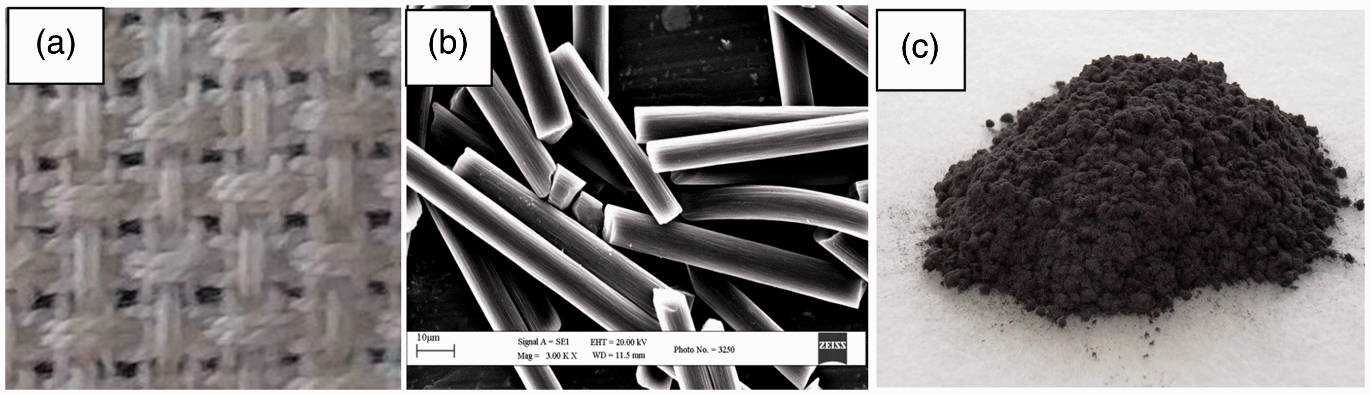

Characterisation of coated fabrics
Scanning electron microscopy
The surface properties and morphological structure of the coated fabric were examined under scanning electron microscopy (SEM) (Model No. EVO 50, CARL ZEISS, low vacuum SEM). The SEM image is formed by the back scattered electron and secondary electron; it is depicted in Figure 2(a) and (b). The darker part of image is formed by the low-energy electron and bright part by high-energy electron.
SEM micrograph of carbon milled fibre coated fabric (a) at 500×, (b) at 2.50 k× magnifications, (c) visual image of coated fabric and (d) cross-sectional image of coated fabric.
Surface resistivity measurement
Surface resistivity ρs is determined by the ratio of DC voltage U drop per unit length L to the surface current Is per unit width D, it is given as HVS free space microwave measurement system. Schematic diagram of planar sample for measurement of scattering parameters (S11 and S21) for a normal incidence of plane wave. Surface resistivity of coated fabric samples.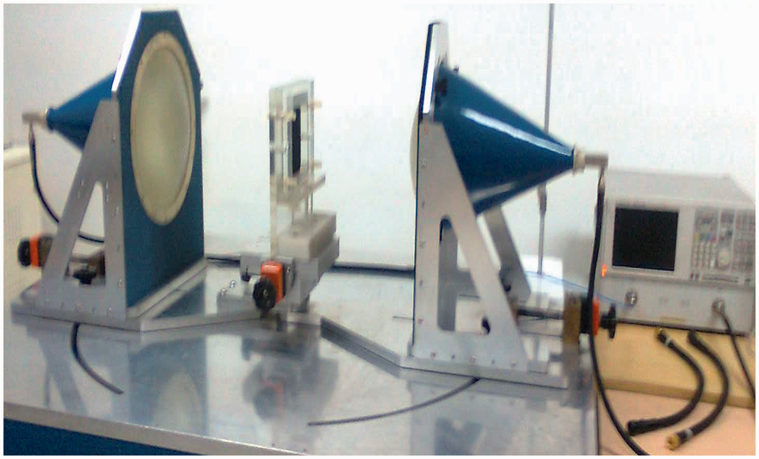

Microwave evaluation
Microwave properties of coated fabric were evaluated in HVS (HVS Technology Inc, State College, Pennsylvnia Bids, USA) free space microwave measurement system shown in Figure 3, in terms of scattering parameters, permittivity, permeability, reflection, transmission, absorption, reflection loss and EMI shielding using Vector Network Analyzer (Agilent, E8364B). Plane polarised wave is emitted from transmit antenna, E-field being in vertical direction, H-field in horizontal direction and wave incidence normal to plane of fabric. S11 and S21 parameters of a planar coated fabric samples were measured in the frequency of 8.2–12.4 GHz (X-band) and 12.4–18 GHz (Ku-band) separately [30].
Scattering parameters
Permittivity at 12.4 GHz and 18.0 GHz and conductivity of coated fabric.

Impedance and tan loss of coated fabric at 12.4 GHz and 18.0 GHz.

Scattering parameters of basic cotton fabric (control fabric).
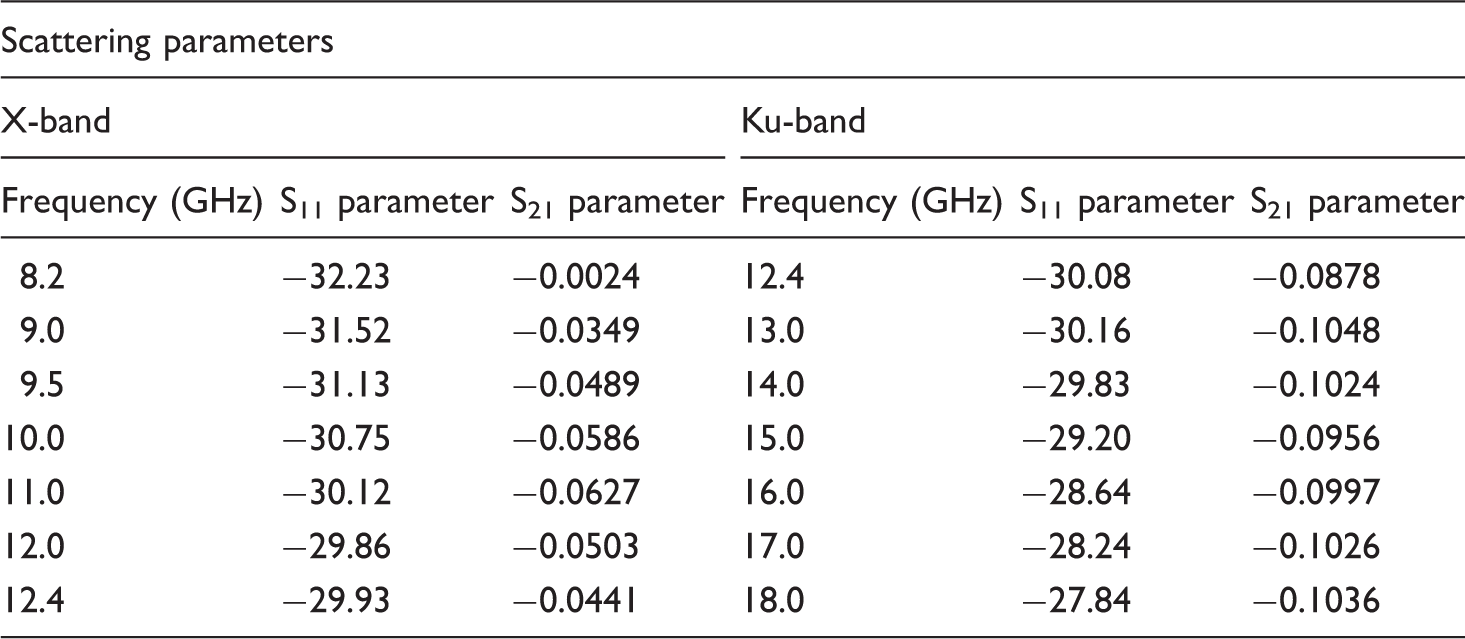
Scattering parameters in X-band.

Scattering parameters in Ku-band.

Results and discussion
Physical evaluation of coated fabrics
Samples of coated fabrics were evaluated for add on, MCF content, PU content and thickness. Details of coated fabric samples are given in Table 1.
Surface resistivity measurement
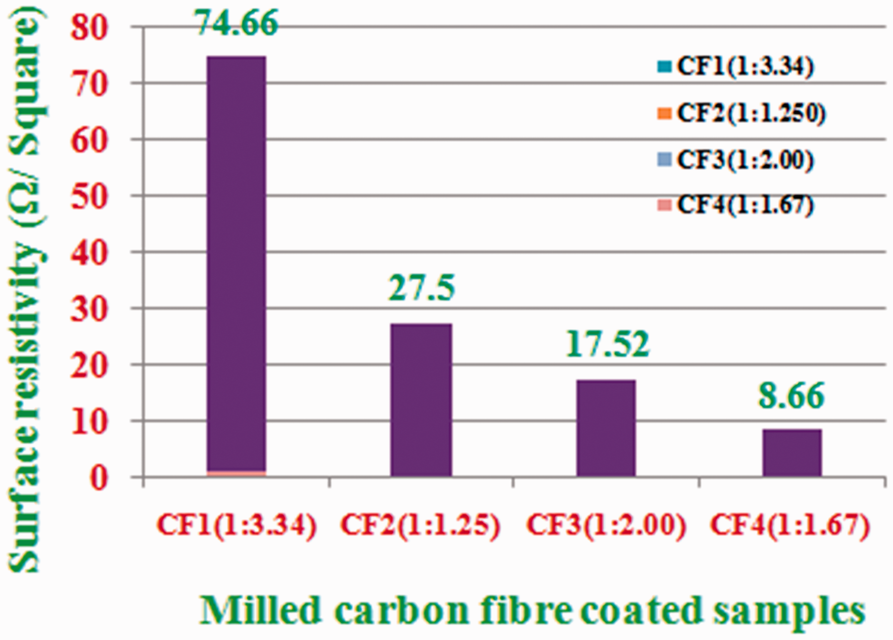
Samples of coated fabrics were evaluated for surface resistivity, the surface resistivity is illustrated in Figure 5. It is observed that as the ratio of MCF to PU increases from value of 1:3.34 to 1:1.67, carbon milled fibre content increases from 23.00% to 37.50% and surface resistivity decreases from 74.66 to 8.66 Ω/□ for samples CF1 to CF4. Low value of surface resistivity offered conductivity of high order.
Measurement of permittivity
The complex permittivity of the coated fabric was evaluated by Vector Network Analyzer (Agilent, E8364B) in the X and Ku frequency bands. The real part is energy storing capacity, whereas imaginary part represents the lossy character of materials. Theoretically, with increase of conductivity, the imaginary permittivity increases as per the equation, Permittivity of MCF coated fabric: (a,b) for X-band and (c,d) for Ku-band for real and imaginary part. Reflection, transmission and absorption of basic cotton fabric (a) in X-band and (b) in Ku-band. (a) Reflection, (b) transmission and (c) absorption of milled carbon fibre coated fabric in X-band. (a) Reflection, (b) transmission and (c) absorption of milled carbon fibre coated fabric in Ku-band.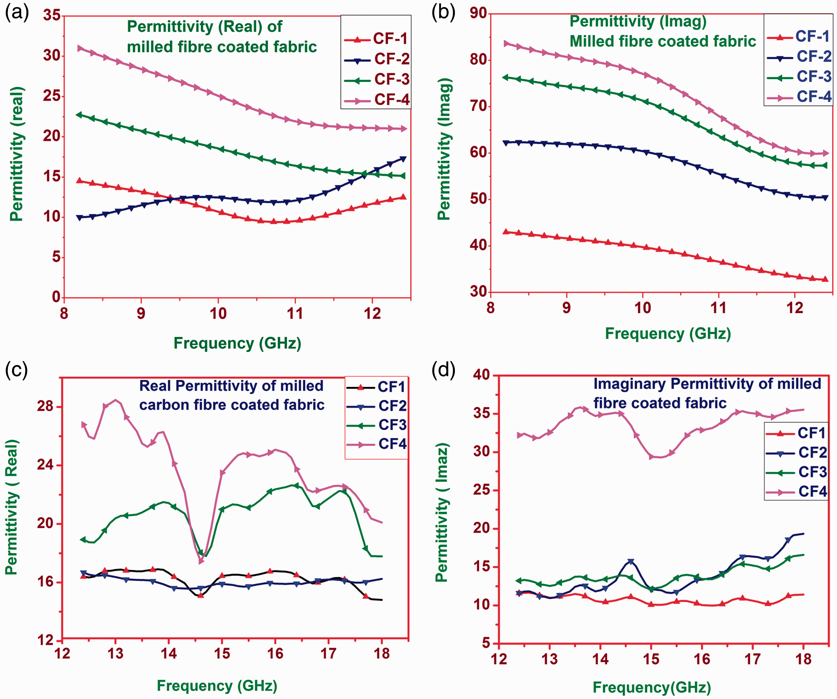


Literature discloses that various microwave absorbers are prepared based on materials with high dielectric properties. Wang et al. [33] prepared E-glass/epoxy composite laminates containing carbon black, carbon nanofibre and multiwall carbon nanotube, CNF offered big electric dipoles and inducing higher dielectric constant of composites due to its high conductivity and straightness. RAM containing carbon nanofibres as dielectric lossy materials and NiFe particles as magnetic lossy materials showed 10 dB absorbing bandwidth of 4.0 GHz in the X-band (2.00 mm thickness) and 6.0 GHz in the Ku-band (1.49 mm thickness). Jang et al. [34] prepared radar-absorbing structure with nickel-coated glass fabric for wing of aircraft. The complex permittivity of the pristine glass-fabric/epoxy composite was 4.57–j0.05 at 10 GHz. After coating the glass fabric with nickel, the complex permittivity of the nickel-coated glass fabrics was 16.31–j4.84 with return loss of −30 dB at 10 GHz at thickness of 1.88 mm. Nam et al. [35] fabricated a thin and lightweight silver-coated glass-fabric microwave absorbing structure in the thickness of 1.82–1.95 mm with good microwave-absorbing performance in X-band (8.2–12.4 G Hz) by silver-sputtering coating technique. Highest value of complex permittivity was 42.47–j26.25 at 10 GHz for 8 min coating time of glass/epoxy composite. The composites are thicker and have shown microwave absorber in mostly X-band only. In the present work, MCF coated fabric have shown good microwave properties in wide frequency band (X- and Ku-bands, 8–18 GHz).
Permittivity and conductivity of coated fabric
The electromagnetic property depends on conductivity as well as dielectric properties depicted in Maxwell’s equation
Scattering parameters of basic cotton fabric (control sample)
Microwave properties of basic cotton fabric (control sample) have been studied; its scattering parameters in X- and Ku-bands (8–18 GHz frequency band) are given in Table 4.
Reflection, transmission and absorption of basic cotton fabric (control sample)
Basic cotton fabric was evaluated for reflection, transmission and absorption. These are shown in Figure 7. From the figure it is seen that mostly the microwave is transmitting, and reflection and absorption are negligible. Thus, towards microwave, the basic cotton fabric (control sample) is almost transparent, total wave is transmitted through it.
Scattering parameters of coated fabric
The scattering parameters of coated fabrics were also measured in 8–18 GHz frequency bands, these are given in Tables 5 and 6.
Calculation of reflection, transmission and absorption of coated fabric
The reflection behaviour of surface depends on surface conductivity which in turn depends on permittivity. Increased conductivity increases the reflection behaviour. As the milled fibre content increases from CF1 to CF4, the surface resistance and impedance (η) decrease and conductivity increases. Reflection, transmission and absorption were calculated on the basis of scattering parameters using equation (1) to (3)


At higher frequency, energy of photon is more and also the penetrating power of wave is more which in turn increases transmission and reduces reflection. Reflection, transmission and absorption of coated fabric samples were evaluated in X- and Ku-bands. The results are shown in Figures 8 and 9. Here, it is observed that with increase of conductivity, reflection increases and transmission decreases for the samples CF1 to CF4. Sample CF4 is highly conductive, its surface resistivity is lowest amongst other samples (8.66 Ω/□), and hence it has offered highest reflection and least transmission. Sample CF4 has shown reflection of more than 70% and transmission less than 0.2%. Sample CF1 is less reflecting due to higher surface resistance, its transmission is higher, hence absorption of sample CF1 is also higher (35–45%) amongst other samples in both X- and Ku-bands.
Reflection coefficient, transmission coefficient and attenuation constant indirectly depend on permittivity. These properties are calculated on the basis of theoretical relations and observed that reflection and transmission coefficients correlate with reflection and transmission behaviour of coated fabric and attenuation constant corresponds to reduction in overall transmission of wave. These are described in brief in the following section.
Reflection and transmission coefficients
The ratio of the amplitude of the reflected and incident electric field is called the reflection coefficient and is designated by Γ (Gamma). The relative amplitude of the transmitted electric field intensity is found by τ (Tau).
Reflection and transmission coefficients of coated fabric samples were worked out using equations (4) and (5) at most prominent frequencies 12.4 and 18.0 GHz


From the above equation, it is seen that if η2 = η1, it means that in homogeneous medium, there is no mismatch in the impedance, reflection coefficient Γ R = 0, i.e. no reflection occurs at interface of two media and transmission coefficient τ = 1 means entire wave energy gets transmitted [36,37].
Reflection and transmission coefficients of coated fabrics at 12.4 and 18.0 GHz.

Attenuation constant (α)
Attenuation of wave means decreasing amplitude while propagating in the medium. Attenuation constant (alpha, α) depends upon tan loss, the ratio of conduction current to displacement current (σ/ωɛ); as the tan loss increases, attenuation also increases. In the lossy medium, electrical and magnetic component both gets attenuated as per the following equation [37]

Attenuation constant of coated fabric was worked out at 12.4 GHz and 18.0 GHz frequencies using the following equation

The attenuation constant is depicted in Figure 10. It is seen that attenuation constant increases from 509.27 to 1971.34 Np/m in X-band and from 555.2 to 2354.14 Np/m in Ku-band for samples CF1 to CF4. Sample CF4 has acquired highest conductivity, hence its attenuation is more and the transmitted wave gets attenuated to the tune of 90% at a depth of 1.2 mm at 12.4 GHz. This sample has shown least transmission (<0.2%). Attenuation comes from absorption; higher absorption means more attenuation or reduction in strength of wave amplitude. Attenuation constant has direct effect on EMI shielding and reflection loss.
Attenuation constant of milled carbon fibre coated fabrics at 12.4 GHz and 18.0 GHz.
Reflection loss
The ratio of power of reflected wave to the incident wave is termed as reflection loss. Reflection loss is usually calculated as a function of thickness of microwave absorption material. Electromagnetic wave cannot be reflected in a uniform material except when there is an interface. For uniform homogeneous material, there is no reflection. Longer wave travel deeper into microwave absorbing material, more the wave will be absorbed. Relative permittivity and permeability of material plays a vital role in absorption of microwave. The value of reflection loss can be adjusted by sample thickness [38].
For further validation of microwave properties of coated fabric, reflection loss was measured by single horn antenna reflectometer measurement system. The source of microwave is vector network analyzer (Agilent, E8364B) operating in the frequency range of 10 MHz–50 GHz. The instrument directly measures reflection loss in dB. Theoretically, at matching thickness and frequency[]

If characteristic impedance of material (Z1) matches with characteristic impedance of transmission line (Z0), RL = 0, there is no reflection loss. The em wave absorption (return loss) for single layer absorber is measured by placing highly conductive plate in back of materials. Material is backed with metal, it is viewed as short-circuiting the transmission line with a load ZL = 0. If there is no transmission line, air and material is the interface, then reflection loss is given as RL = 20.log[(√(µ/ɛ)−1)/(√(µ/ɛ)+1)], where µ and ɛ are the relative permeability and permittivity of material [40].
Reflection loss depends on absorption and destructive interference between incident and reflected wave. More is the absorption, higher is the reflection loss. The coated fabrics have shown high reflection and low absorption and hence reflection loss is comparatively moderate. Amongst the span of our experiment, absorption of sample CF1 is highest, its reflection loss is also higher (−2.4 to −3.0 dB) in both X- and Ku-bands (Figure 11(a) and (b)).
Reflection loss of coated fabric (a) in X-band and (b) in Ku-band.
Electromagnetic shielding effectiveness
The material which protects a body, environment or a circuit from harmful electro-magnetic radiation is called shield. Shields are used either to isolate a space (a room, an apparatus, a circuit, etc.) from outside sources of electromagnetic radiation or to prevent the unwanted emission of electromagnetic energy radiated by internal sources. Typical materials for electromagnetic shielding include sheet metal, metal screen and metal foam [41]. EMI shielding is accomplished by reflection and absorption of wave during propagation. Higher reflection and more absorption offer maximum EMI shielding. Reduction of strength of transmitted wave corresponds to overall EMI shielding effectiveness. So, less transmission means higher EMI shielding effectiveness. It is reported that as the frequency increases, EMI shielding effectiveness decreases. At lower frequency, material offers higher EMI shielding in comparison to higher frequency. Due to higher reflection and absorption, the coated fabric behaves as barrier to the microwave and hence can provide effective EMI shielding. Therefore, samples were also studied for EMI shielding effectiveness.
EMI shielding effectiveness of coated fabric
Total shielding effectiveness is the overall attenuation of transmitted em wave as a result of reflection, absorption and multiple internal reflections at the existing interfaces [42–44]. It is expressed as

The loss due to multiple reflections is ignored when SEA is more than −10 dB, as explained by the equation 

In general, MCF coated fabrics have shown highest reflection and least transmission of electromagnetic wave. Sample CF4 has shown reflection more than 70% and transmission less than 0.5%, EMI shielding is more than −28.5 dB in X-band (Figure 12(a)). In Ku-band, transmission is less than 0.2% and EMI shielding is more than −29 dB (Figure 12(b)).
EMI shielding effectiveness of coated fabric (a) in X-band and (b) in Ku-band.
Flexibility and durability
Flexibility of the coated fabric was studied by evaluating the bending length, using Shirley Stiffness Tester (BS: 3356: 1961). Bending length lies in between 3 and 4 cm, and bending modulus in the range of 34–80 kg/cm2. These values refer to adequate flexibility.
Durability of coating materials was evaluated by abrasion test and flexing test, these are mentioned below.
Abrasion test
The adhesion of coating materials on fabric against friction/rubbing action was tested by Martindale Abrasion Tester (ASTM D 4966) (Figure 13). The abrasion depends on abradant, pressure on sample holder and number of cycles to run. For coated textile materials, emery paper (Bear, fineness 600 no.) was used as abradant. Sample was run for 100 cycles under a pressure of 628 g. The coated fabric and abraded fabric are shown in Figure 13(b) and (c). It is seen that after abrasion, there is no significant change in coating layer. After 100 cycles, the loss in weight of coated fabrics is in the range of 1.75–2.36%. This is insignificant and this shows strong adhesion of coating with the fabric. The abrasion test results are given in Table 8.
(a) Martindale Abrasion Tester, (b) control coated sample and (c) tested piece. Abrasion test results of coated fabrics.

Flexing test
Durability of coated fabric was tested in Dematia Flex Tester (IS: 7016 part 4). Three-fold folded sample of size 4.5 cm × 12.5 cm was mounted between reciprocating jaws. Samples were run for 30,000 cycles. After 30,000 cycles, no mark of cracks of coating, flexing, de-lamination of coating or wrinkles was observed. The tested sample is shown in Figure 14(b). It is seen that coated fabric is adequate flexible, strong adherence of coating which can withstand frequent folding and unfolding operations. Thus, coated fabrics have sufficient flexibility and durability.
(a) Dematia Flex Tester and (b) tested sample of coated fabric.
Conclusions
MCF in PU matrix applied on cotton substrate has generated high dielectric conductive system which acquired properties to interfere with microwaves falling on it. Fabric coated with formulation containing MCF and PU in ratio of 1:1.67 offered highly conducting and flexible surface that culminated into interaction with microwave. Coated fabric exhibited 67–70% reflectance, 28–30% absorption, 0.1–0.5% transmission and EMI shielding of 28–30 dB in 8.2–18 GHz frequency band in 1.12 mm thickness. Although in the present study, microwave properties were measured in 8.2–18 GHz frequency range, but at lower frequency, i.e. in MHz range, the coated fabric would have more reflection with reduced transmission and increased EMI shielding. Therefore, the properties of coated fabric can be modulated and tuned in wide frequency band by changing types of substrate fabric material, type of PU, content of MCF for variety of applications, e.g. radar absorbing structural materials, radar camouflage, stealth materials and EMC and EMI shield material and protection from human being from hazardous microwave.
Footnotes
Acknowledgements
The authors are grateful to Dr KU Bhasker Rao, Ex Director, DMSRDE, Kanpur, and Dr N Eswara Prasad, OS/Scientist ‘H’ and present Director DMSRDE, Kanpur, for their kind permission for carrying out experimental work and characterisation of samples. The authors also express their thanks to Prof K Balasubramanium, HoD, Department of Materials Engineering, DIAT, Pune, for his guidance and technical support.
Declaration of conflicting interests
The author(s) declared no potential conflicts of interest with respect to the research, authorship, and/or publication of this article.
Funding
The author(s) received no financial support for the research, authorship, and/or publication of this article.