
Abstract
In this study, hybrid and 100% carbon woven fabrics have been investigated for their electromagnetic shielding performance in the frequencies, ranging from 700 MHz to 3 GHz. The shielding effectiveness of plain, twill, and satin woven fabrics was assessed by free space measurement technique. The experimental results showed that carbon-based woven fabrics have an optimum electromagnetic shielding efficiency at different measured frequencies. As expected, the shielding effectiveness of the structure improved with the amount of carbon yarn in the fabric structure. Analyses of the different weave types revealed that twill 2/1 fabric construction showed the best performance compared to the others due to the large number of intersection points of yarns in the fabric structure.
Keywords
Introduction
With the incredible acceleration of technological advances, people have started to use more and more technological electrical devices every day which caused them to be exposed to much more electromagnetic (EM) radiation. The most common type of electromagnetic interference (EMI) occurs in the radio frequency (RF) range of the EM spectrum, from 104 to 1012 Hz (Figure 1). This energy can be radiated by computer circuits, radio transmitters, fluorescent lamps, electric motors, overhead power lines, lightning, and many other sources. Shielding of EM is becoming more critical due to the smaller size and faster operating speeds of these components, which make it more difficult to manage the EM pollution they create [1].

The electromagnetic spectrum [2].
Certain potential health hazards, such as skin diseases, weakening of body parts like eyes and nerve cells, psychological disorders etc., of EM radiation to human body are well known and some of them are still being investigated [3]. At the same time, a great deal of effort is made for the development of shielding materials. EM shielding provides protection from EM radiation by reducing signals to levels at which they no longer affect or can be no more received. This is achieved by reflecting and/or absorbing the radiation [4]. Several methods are used for shielding the EM radiation. These methods can be classified into two groups, namely “surface treatments” and “fillers.” In the surface treatments, conductive materials are applied on the surface of the shielding material. Ionic plating, electroless plating, cathode sputtering, conductive paints, vacuum metallization, zinc paints, zinc flame spraying, zinc arc spraying are some examples of surface treatment [5]. In the second group, conductive materials such as fibers, particulates, or textile fabrics can be used as fillers. Textiles are naturally non-shielding materials, but still can be turned into an EM shielding material by using conductive fibers or yarns at the production stage. Naturally conductive fibers or metallic fibers are obtained from electrically conductive metals such as ferrous alloys, nickel, stainless steel, titanium, aluminium, copper, etc. Other naturally conductive fibers are carbon fibers and fibers made of inherently conducting polymers [6]. In recent years, conductive fabrics manufactured from conductive yarns have been highly considered for EM shielding applications in the electrical and electronic industries as well as for the production of protective garments owing to their desirable properties in terms of flexibility, versatility, low mass, and low cost [7]. Conductive fabrics can be produced by knitting, weaving, or nonwoven technology. Among all, fabrics woven with conductive yarns are being increasingly utilized in shielding of EM and for anti-electrostatic purposes in the defense, electrical, and electronic industries [8]. Researchers used various fiber types in producing shielding woven materials. Liu and Wang, used cotton and stainless steel yarns in order to obtain plain, twill, and satin fabrics with EM-shielding capabilities [5]. They observed that the yarn float was the key influencing factor without changing other parameters of fabric. They also found that shielding efficiency of the plain woven fabric was better than twill and satin woven ones. Cheng et al. used stainless steel/polyester blended yarns in the production of woven fabrics [9] and concluded that the developed conductive fabrics may be suitable in the use of home electrical and electronic appliances. Perumalraj and Dasaradan, firstly produced two-ply and three-ply cotton copper yarns then transformed them into plain and twill woven fabrics [10]. The obtained fabrics provided an attenuation of 40 dB to 74 dB at a medium frequency range of 700–5000 MHz which makes them available in the shielding of household appliance, FM/AM radio broadcasts, wireless phones, cellular phones, computers, buildings, secret rooms, and various electronic gadgets [10]. Lai et al., applied metal coating films on metal/polyethylene terephthalate (PET) woven fabrics and measured their electromagnetic shielding effectiveness (EMSE) capabilities in their study [11]. The experimental study indicated that different coating materials exhibited different EMSE values and as thickness of the coating material increased, the value of EMSE increased [11]. Cheng et al., studied the EMSE of the twill 3/1 fabrics made of copper filament with varying ends per inch, picks per inch, and diameter of copper wire. They observed that as the diameter of copper wire increased, the EMSE value decreased [12]. Also Liu et al., studied about the influence of the metal fiber content on the shielding effectiveness (SE) and they constructed an index of metal fiber content per unit area [13].
Carbon fibers have very attractive properties such as strength, electrical conductivity, stability on exposure to reactive media, low density, low-to-negative coefficient of thermal expansion, and resistance to shock heating all of which give carbon fibers a good potential in EM-shielding applications [1,6]. The electrical properties of carbon fibers are explained in terms of π-electron delocalization. It is known that percolation occurs due to tunneling or hopping of electrons from one fiber to other fiber or by actual formation of a nanofiber network [6]. In spite of carbon fibers’ attractive features, most of the studies reported on woven shielding materials were generally concentrated on metal and copper yarns. To the best of our knowledge, there is only one study available in the literature which investigated the SE of carbon fabrics in the woven form. Palanisamy et al., produced various types of shielding materials two of which were plain and satin carbon woven [14]. They compared totally 32 types of conductive materials and found that plain carbon woven showed an increasing EMSE value with the increasing frequency which embodied the EMSE around 57 dB at 1.5 GHz frequency; on the other hand, satin carbon woven fabric showed almost independent EMSE at the frequency of around 49 dB.
The primary object of this research was to compare EMSE of carbon-based woven fabrics. For this aim, 100% cotton, 100% carbon, and hybrid woven fabrics have been manufactured. Carbon yarns were used as conductive fillers in hybrid woven fabric in order to observe the difference between 100% carbon woven ones. The samples in the form of plain 1/1, twill 2/1, and satin 6 woven fabrics have been tested in a nonreflective room for observing the EMSE in the frequencies, ranging from 700 MHz to 3 GHz.
Experimental
Material
The cotton yarn used in weaving of fabrics was 180/3 tex. The carbon used in our study was AKSACA™ and it was purchased from DowAksa, Turkey. The carbon yarn was multifilament and 3 K which refers to 200 tex of fineness. The symbol “K” is used mostly for multifilament carbon yarns and corresponds to a 1000 of untwisted filaments per a tow. 1 K means 1000 filaments/tow and 3 K means 3000 filaments/tow.
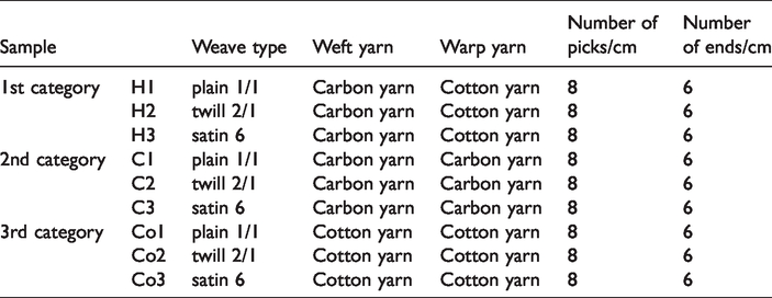
The materials assessed in this study can be classified into three categories. First category was comprised of hybrid fabrics which were woven from cotton and carbon yarns. Second category was woven from 100% carbon yarn and the third category was woven from 100% cotton yarn. Each category was consisting plain 1/1, twill 2/1, and satin 6 fabrics. Specifications samples are shown in Table 1. Schematic diagrams of these weave structures are also given in Figure 2.
Specifications of woven fabrics.

Schematic diagrams of woven structures. (a) plain 1/1 weave, (b) twill 2/1 weave, and (c) satin 6 weave.
An automatic sample loom was used in manufacturing of fabrics. The reed count was 6 and during the sleying, the warp yarns were passed through the dents of the reed one by one. While the fabric is being woven, the reed holds the fabric out to nearly its full width. But after removing the fabric from the loom, the warp yarns are drawn closer. The amount of shrinkage depends on some factors, two of which are the character of the yarn and weave pattern. As the yarn characters and weave patterns were different in the study, after removing from the loom the warp and weft densities differed from the initial state. Therefore, in Table 1, we gave the densities of the weft and warp yarns on the reed.
Measurement of EMSE
Shielding effectiveness is a term that defines the amount of shielded field for a specific frequency or frequency range [15].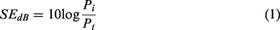
The mathematical definition of shielding effectiveness is given in equation (1) where Pi is the incident field on a planar material and Pt is the transmitted power from this material. There are some proposed methods in literature to measure this parameter [15,16]. ASTM D4935-10 is most widely used method to measure shielding effectiveness of a planar material [16]. In this method, a large coaxial specimen holder is used. But as the standard suggest, this method is valid for the frequency range of 30 MHz–1.5 GHz which does not cover 1800 MHz GSM, 2100 MHz 3 G, and 2400 Wi-Fi bands.
The free space measurement method proposed by Wieckowski and Janukiewicz [17] is widely used in the literature due to its easy setup compared to the ASTM D4935-10 standard and wide frequency band [18–22].
Until 1970s, RF measurements were used to hold in open areas. However, it is known that such a system can be affected from other sources. It is sometimes can be obligatory to separate all other sources but to investigate one specific source. RF anechoic chambers are used in such situations. An RF anechoic chamber is a box which is shielded with very good conductors to prevent outer RF sources to interfere the ongoing measurement. Interior of the chamber is covered with absorber materials which decrease the reflections inside the chamber for the desired frequency range. Simmons and Emerson [23] proposed an RF anechoic chamber with such absorbers. The dimensions of RF anechoic chambers depend on the measurements that are held in the chambers. Some of these chambers are as large as 21 m × 13.5 m × 8.5 m. Such a chamber can be used from 150 kHz up to 18 GHz [24].
It is obligatory that the RF fields inside the anechoic box to be plane waves. This can be ensured to place the antennas with a distance of at least far-field of the antennas used (Figure 3). Also, the designed or bought antennas’ radiation patterns are calculated in the far-field zone. With a distance smaller than the far-field, these anticipated radiation patterns are not accurate. The far field of the antenna is proportional to square of its largest dimension and inversely proportional to the wavelength.

The measurement setup: Anechoic chamber measurement technique.
The receiver and transmitter antennas are preferred to be directional antennas. Also, for a fast and accurate measurement, an antenna that covers the whole frequency band of interest is needed. Two log periodic antennas from Gigahertz Solutions are preferred for our system. The maximum dimension of the antenna is 17 cm. The calculated far-field for this antenna is 58 cm for 3 GHz and 14 cm for 700 MHz. In order to keep the chamber dimensions at its minimum, flat laminate absorbers are preferred. This kind of absorbers has less absorption, but they are smaller in size compared to the high-performance pyramidal absorbers. ETS-Lingdren FL-4500CL (−25 dB average absorption at 455 MHz and above), FL-2250CL series absorbers (−30 dB average absorption at 940 MHz and above) are chosen for this purpose. The outer conductor is stainless steel. The whole structure is mounted on wheels to provide mobility. The doors are sealed with conductive gaskets in order to prevent EM leakage.
In this study, the shielding effectiveness of samples was measured using free space measurement technique with an anechoic box. The frequency band is chosen as 700–3000 MHz. This band includes many important Industrial, Scientific and Medical (ISM) bands such as 900 MHz GSM, 1800 MHz GSM, 2100 MHz 3 G, and 2400 MHz Wi-Fi/Bluetooth. The practical measurement setup and measurement of samples are shown in Figures 4 and 5. A spectrum analyser, Anritsu MS2711D (Anritsu, Morgan Hill, CA, USA) with the option of transmission measurement was used for the tests. In transmission measurement option, reference level without shielding material under test was taken automatically with normalization process and the signal level with the material was compared in logarithmic scale in terms of RF power which automatically takes the effects of losses such as cable, connection, instrumentation, and free space into consideration. In this manner, the chamber is calibrated before every measurement.

Practical measurement setup. (a) Closed view of the anechoic box. (b) Open view of the anechoic box.

Measurement of woven samples.
Results and discussion
The cotton fabric samples woven without conductive yarns have SE below 1 dB. Therefore, the EMSE figures of these samples were ignored in this paper.
The hybrid plain 1/1, twill 2/1, and satin 6 fabrics were woven by using cotton warp yarns and carbon weft yarns. The SE figures of these hybrid fabrics were presented in Figures 6 to 8, respectively. Vertical measurements of these fabrics gave comparable curves and since they are all lower than 5 dB it can be concluded that, in this direction, the fabrics have almost no shielding effect due to the cotton warp yarns which have no conductivity; only exception to this was observed in the 2235 MHz with the twill fabric having a shielding effect of 6 dB. When the vertical measurements are carried out; the sample fabric was hanged in the anechoic chamber as shown in Figure 6(a). Since warps of the hybrid fabrics are made of cotton which do not possess electrical conductivity, the hybrid fabrics did not effectively shield the EM field.

(a) Vertical measurement setup and (b) horizontal measurement setup [25].
Comparing SE figures of plain 1/1 and twill 2/1samples in horizontal direction, it could be observed that the plain woven fabrics have lower shielding properties than twill fabric between 1000 and 1263 MHz interval (Figures 7(a) and 8(a)). This situation contradicts with the literature which claims plain woven fabrics’ shielding efficiency better than twill fabric [5]. This difference between two studies may be due to the fact that the raw materials used in the fabrics are not same. Furthermore, between 1723 and 2160 MHz interval, plain and twill woven fabrics showed comparable shielding effect with the SE values. However, after 2281 MHz the plain 1/1 weave showed higher shielding properties compared to the twill 2/1 fabric.

The EMSE of plain 1/1 fabric H1. (a) Horizontal measurement and (b) vertical measurement.

The EMSE of twill 2/1 fabric H2. (a) Horizontal measurement and (b) vertical measurement
The SE values of plain 1/1 knitted fabrics are higher than 10 dB between the ranges of 1220–1385 MHz, 1735–2109 MHz, 2219–2638 MHz, and 2840–3000 MHz (Figure 7(a)). Meanwhile, the SE values of twill 2/1 fabric are higher than 10 dB between 1000–1419 dB, 1735–2109 MHz, and 2206–2551 MHz (Figure 8(a)).
When the satin fabric is examined in horizontal direction, it is observed that the satin fabrics shielded less than the twill and plain woven fabrics (Figures 7(a), 8(a), and 9(a)). Especially in the middle- and high-frequency ranges, the measured SE values of satin fabrics are lower than twill and plain woven fabrics. The satin fabrics have lower intersection points of weft and warp yarns. The intersection points lead to more dense microstructure which causes higher EM-shielding performance. Furthermore, some previous studies reported lower shielding effect of the satin weave compared to the other weave types due to the long floats [5]. The SE of satin weave is higher than 10 dB only in two intervals, namely 18 dB between 912 and 1073 MHz and approximately 15 dB, between 1689 and 2005 MHz.

The EMSE of satin 6 fabric H3. (a) Horizontal measurement and (b) vertical measurement.
The horizontal and the vertical measurements of the SE of plain 1/1, twill 2/1, and satin 6 fabrics which are woven using 100% carbon yarns are presented in Figures 10, 11, and 12. Apart from the first group of the samples, it can be observed that both the horizontal and the vertical SE measurement results of the second sample groups have shielding effects in certain frequency ranges. Nevertheless, each group has some differences in terms of shielding efficiency.

The EMSE of plain 1/1 fabric C1. (a) Horizontal measurement and (b) vertical measurement.

The EMSE of twill 2/1 fabric C2. (a) Horizontal measurement and (b) vertical measurement.

The EMSE of satin 6 fabric C3. (a) Horizontal measurement and (b) vertical measurement.
If the vertical and horizontal measurements of the plain fabric (C1) are examined (Figure 10) between 1022 and 1344 MHz, it can be concluded that the vertical measurements have a peak at 1230 MHz with a shielding effect of 27 dB. On the other hand, the horizontal measurements showed a more widespread shielding effect above 10 dB on the same frequency band. Between 1585 and 2229 MHz, both directions have almost the same shielding effect. Only a slight difference has been observed at around 2000 MHz range. While the shielding effect tends to decline in horizontal measurement between 2632 and 2750 MHz, the vertical results have shown an increase trend up to 25 dB in the opposite way.
When the EMSE results of twill 2/1 fabric (C2) investigated both in the horizontal and vertical direction, it can be concluded that both directions have a shielding effect above 5 dB almost in all frequency ranges. As seen on Figure 11, it performed below this value only in a very small range (before 1102 MHz and around 1585 MHz). Between 1102 and 1585 MHz, the vertical direction shielded better than the horizontal one. However, between 1666 and 2149 MHz intervals, horizontal direction showed better results. This opposite performance behavior was also observed between 2149–2390 MHz, 2471–2793 MHz, and after 2873 MHz range. It can be thought that these differences, in this sample containing 100% carbon yarn, are due to the fact that the fabric structure in the horizontal and vertical direction is different from each other. So this case resulted in approximately periodic repetitive increases and decreases.
When it comes to the results of satin fabric samples (C3), between 941.5 and 1585 MHz, it can be said that the vertical and horizontal measurement results have similar curves, only the peak values are different. The horizontal measurements reach above 15 dB at 1022 MHz, while the vertical ones have a shielding efficiency above 30 dB at around 1183 MHz. Between 1666 and 2149 MHz interval, both directions have a performance above 35 dB. The measurement at horizontal direction results in a better performance after 2390 MHz.
When it comes to compare the SE performances of C1–C2–C3 sample groups for horizontal direction; it can be said that below 1585 MHz, the twill fabric (C2) has better results according to the others. For this range, the satin fabric (C3) has the lowest performances. Although the peak values are higher for C1 and C3 in some certain frequencies, C2 performs better in general for 1585 MHz and 2310 MHz interval. Finally, after 2310 MHz, C2 and C3 have very similar results while C1 have lower performance.
As for vertical direction results of C1–C2–C3, it can be concluded that; up to 1585 MHz, all samples have comparable curves with slight differences. Between 1585 and 2310 MHz, C1 have shielded better but around 1827 MHz C3 have the highest peak values. After 2310 MHz, C1 have the better results comparing the other two samples. C3 have the lowest values for this range.
Conclusion
The EM-shielding performances of hybrid and 100% carbon woven fabrics with various fabric constructions have been investigated in the study. For this purpose, sample materials have been woven by using carbon and/or cotton yarns with various fabric structures in the first phase of the study. Furthermore, the shielding effectiveness of plain, twill, and satin woven fabrics have been tested in a non-reflective room in order to determine the EMSE in the frequencies, ranging from 700 MHz to 3 GHz.
As a result of the investigations, Vertical measurements of hybrid (warp cotton, weft carbon) plain woven, twill, and satin fabrics, displayed curves lower than 5 dB which means that in this direction, the fabrics have almost no shielding effect due to the cotton warp yarns that have no conductivity The horizontal EM shielding values of the hybrid samples provided better results because of the type of weft yarns (carbon) and their arrangement in the fabric construction. Apart from the hybrid samples, both the horizontal and the vertical SE measurement results of the 100% carbon samples have shielding effects in certain frequency ranges. When hybrid woven fabric types compared to each other, twill fabrics displayed better shielding between 1000 and 1263 MHz interval. However, after 2281 MHz, the plain weave showed higher shielding properties compared to the twill fabric. Since textile materials are essentially in fiber-based construction, homogeneous distribution of conductivity like other rigid materials may not be possible. Therefore, even if the amount of conductive material in the unit area/surface is considered as equal, the experimental performance of the samples can be observed differently due to the variations in the distribution of conductive materials in terms of microstructure. The cotton fiber is in a characteristic twisted structure in its natural form, while carbon fiber has a structure of multifilament fibers. These variations may lead to differences in EM-shielding performance. The hybrid satin fabrics shielded less than the twill and plain-woven fabrics especially in the middle- and high-frequency ranges. The satin fabrics have lower intersection points of weft and warp yarns. Less intersection points lead to less dense microstructure which causes lower EM-shielding performance. Apart from the hybrid samples, both the horizontal and the vertical SE measurement results of the 100% carbon woven fabrics had shielding effects in certain frequency ranges. Nevertheless, each group had some differences in terms of shielding efficiency. According to the SE performances of 100% carbon fabrics in horizontal direction, the twill fabric generally showed better results comparing to the others and the satin fabric had the lowest performances. As for vertical direction results of 100% carbon fabrics, it can be concluded that; up to 1585 MHz, all samples had comparable curves with slight differences. Between 1585 and 2310 MHz, plain weave shielded better but around 1827 MHz satin weave had the highest peak values. After 2310 MHz plain had better results comparing the other two samples. These variations may probably due to the unstable structure of textile fibers.
Footnotes
Declaration of conflicting interests
The author(s) declared no potential conflicts of interest with respect to the research, authorship, and/or publication of this article.
Funding
The author(s) received no financial support for the research, authorship, and/or publication of this article.