
Abstract
With increased utilisation of simple fabrics in technical engineering and manufacturing environments the need for suitable, easy to implement material representations in simulation software has increased. A simple implementation of plain woven polypropylene fabric for inflation simulation of dunnage bags is developed. Only standard finite element software packages and a simple material calibration protocol based on numerical optimisation were used to generate a homogenised material representation for the in-plane properties of plain woven polypropylene undergoing both loading and unloading. This is achieved by performing a simple material test that represents the in situ loading state of the material, measuring the applied load and material deformation in response to that load, and mapping that response to a simulation of the same test by means of an inverse problem statement. Following the proposed method, a material response model for plain wove polypropylene was developed that captures the major responses of a measured woven test specimen.
Introduction
With the drive towards more effective, low-cost, structural solutions, there has been a resurgence of interest in inflatable tensile structures due to their efficient use of material. Inflatable tensile structures use a contained gas volume to pretension load bearing material. These structures have several advantages over conventional solid structures, including lightweight, a high stowed to deployed volume ratio and more evenly distributed loads [1]. In addition to these advantages making inflatable products popular in the aerospace industry, inflatable products have gained popularity as commodity products, because they can be manufactured from inexpensive commodity grade, recyclable materials [2]. As interest in inflatable technology grows, for both high and low technology applications, there is a growing need for simulation tools capable of capturing the complex load cases often associated with these structures to simultaneously provide insight into the characteristics of new structures and predict their performance.
The example used in this article is a dunnage bag, which is an inflatable pillow-shaped tensile structure used to secure goods in transit. Typical loading for a dunnage bag include inflation into position, which represents a continuously applied tensile load, after which the bag will be subjected to cyclic loading and infrequent overloading.
Here the manufacturer is interested in evaluating critical areas in existing designs as well as investigating changes that will allow for faster product development. Previous research into simulating dunnage bags found that most of the technology is in place to successfully simulate new inflatable products. However, a method of effectively representing the types of materials involved needs to be found [3].
Dunnage bags are manufactured from plain woven polypropylene, which is known to have a complex nonlinear material response. Woven polypropylene has a nonlinear response that is a combination of the nonlinear responses of both the underlying polypropylene substrate and the textile architecture [4]. Furthermore, to minimise the material used in each dunnage bag, the bag is designed such that the material is loaded well into its plastic response.
Several approaches are available to model this class of material. The most common methods are kinematic and analytical material models [5–7], and macro-, micro-, and meso-scale modelling of the weave architecture [8–10]. Each of these methods are either computationally expensive, require significant material testing, user defined subroutines or consider the complex fibre interactions of the woven material.
This research aims to propose a simple method of generating a material representation for plain woven polypropylene fabric, with the following objectives:
The material representation should already be implemented in a commercial finite element software package and not require any user defined subroutines. Calibration of the material representation should only require testing of the material in a manner similar to the expected load case. Only the overall response of the material should be represented. The material representation should respond to in-plane loading in the same way as a material specimen over a predetermined strain range. Both the load and unload characteristics of the material should be captured.
Material and methods
Woven textiles and fabrics are non-continuous materials with anisotropic mechanical properties. The material response of the woven textiles is only partly based on the material properties of the base material. In addition to the material properties of the constituent fibres, the material response of a woven textile is dependent on the mechanics and geometry of the weave architecture. The polypropylene tows used in dunnage bags are pre-stretched to increase their stiffness and reduce their elongation to break. This operation makes each tow highly orthotropic. The properties of the warp and weft tows in the weave also differ in their feedstock, geometry and the amount with which they are pre-stretched giving them material properties that generally do not match.
Polypropylene itself has a complex and uncommon load–unload relationship, which is further complicated when the material is subjected to multi-cycle loading [11]. It is noted that the load response for polypropylene changes with each load application. The varying cyclic-response and complex load–unload curves for polypropylene will permeate into the properties of the woven polypropylene textile fabric.
Woven materials can have significantly different properties from those of their constituent fibres, most notably that the shear and elastic moduli are dependent on the weave architecture. The nonlinear shear response is caused by the fibre trellis interaction and the coupled tensile response between the warp and weft material directions is caused by the crimp de-crimp behaviour of the material [12]. Woven fabrics are non-homogeneous, non-continuous materials, which are often modelled as a continuous orthotropic material. However, the orthotropic assumption is only applicable when the loading is predominantly in-plane in the fibre directions of plain woven materials. In these cases, the warp and weft provide the material strength in the primary directions [13].
The material shear and biaxial load response are dependent on the biaxial tension ratio and shear state, making these co-dependent characteristics [14,15]. In many cases, such as out-of-plane loading or draping, the primary material directions are no longer the only load directions [16]. Here, the shear characteristics of the woven material become a prominent factor, because the shear strength of a plain woven fabric is not related to the elastic modulus in the primary material directions. This means that a woven fabric cannot be simulated as a continuum. For practical reasons, the material cannot feasibly be modelled on a large scale on a fibre by fibre basis.
The material mechanics of woven textiles can be investigated at various levels depending on the area of interest. Textile modelling strategies are provided at the fibre, yarn, weave and fabric levels [17]. Different assumptions are made on each level. For the purposes of this research, only the response of the material as a whole is of interest and the properties will be determined at the fabric level. In this case, a property homogenisation technique is required to produce an equivalent continuum property that closely resembles the properties of the actual woven material over the domain of interest for an analysis.
Material homogenisation
In this research, the micro mechanical interaction of the fibres are not of interest and the computational load of simulations at that level on the scale of a dunnage bag is too large to be practical. Several techniques are found in literature that reproduce the response of the mechanical fibre interactions and constituent material properties as an average over an area. The material properties of a representative material section is homogenised and applied to the entire structure. Three general approaches are evident in literature for modelling woven textiles: meso-scale modelling, parameter identification using unit cells and material response matching. Each of these is briefly discussed below.
Meso-scale modelling of woven textiles take into account the mechanics and interactions of individual fibres and tows as well as the material properties of the fibres themselves. This form of modelling is capable of capturing the contact friction, crimp, bending and shear behaviour of a woven fabric, but the computational demand is high [18].
The purpose of homogenisation is to reduce the number of elements required for a numerical model while still representing the overall mechanics of the system. Numerical unit cells make use of a small repeating, representative area of material where the inter-fibre mechanics can be reasonably accounted for or modelled. The load response of the unit cell is averaged and used to represent the response of the entire area. Two classes of unit cells exist, analytical unit cells and numerical unit cells. Analytical unit cells attempt to account for the micro-mechanical properties of a representative area of material by some analytical means. These models are typically implemented as user-defined materials in commercial software. Numerical unit cells attempt to account for the micro-mechanical properties of a representative area of material by means of a numerical model.
Early efforts to find the effective properties of composite materials used an analytical approach. These were later adapted to be analytical models based on some recurring unit cell, and lately adapted to include numerical simulations on a unit cell geometry [19]. In each case, the main problem is that, although the geometry of the unit cell can be chosen to be repetitive, it is difficult to generate boundary conditions that abide by the symmetry conditions required by a unit cell. Despite these limitations, the unit cell method of homogenisation is a commonly used and effective technique used on woven textile fabrics.
The response matching method of material homogenisation does not attempt to account for any micro or meso-scale characteristics, either through direct modelling of the weave or through analogous unit cells. That is, only the response of a larger scale material test is considered. The overall properties of the material are simply transposed on a single representative finite element. This method was used to develop a continuum model for woven material for use in ballistic simulations [20].
It is noted that from a practical point of view, most material models available for the simulation of woven textile fabrics are too complex for effective use in large simulations [21]. Most sources recommend that the material be homogenised in an attempt to match the response of the material as a whole to typical loads without being encumbered by the material detail. For many applications, it has been found that the response of a standard linear elastic orthotropic material model can be used to represent the material properties of fabrics over the region of interest of the simulation. A trial and error approach has been used to match the response of a fabric measured in physical testing to a simulation of the same test. This article will later show that this trial and error approach can be improved using optimisation.
For the purpose of this article, material property homogenisation is the process of describing the average response of the woven fabric to a mechanical load. Furthermore, this average response will be described in terms of a standard material model available in a commercial finite element package.
As a result of homogenisation, model detail is lost. It is therefore important to decide what detail is required. In most cases, the homogenised material model will focus only on the in-plane material response. For dunnage bags, there is a very large difference in dimensions between the bag's overall length and width, and the material thickness, leading to the assumption that the material can be considered a membrane. This eliminates any requirement for out-of-plane material response from the homogenised material. Using a homogenised material property has several drawbacks caused by the fact that the homogenised material does not match the mechanics of the true material. As an example, the stress in the body being simulated is not representative of the stress in the physical material, meaning that the homogenised material model will make use of a surrogate stress–strain relationship not related to the physical material. Different homogenised material models can also be used to represent the response of the same material, each matching different parts of the material response. The errors inherent in the use of a surrogate material can be limited by a clear statement of the desired responses and the range over which those responses are of interest.
The operating environment for dunnage bags has them frequently loaded and unloaded, thus the load–unload response of the woven material in the warp and weft directions are of interest. Material shear response is not evaluated because there is very little shear in the failure regions of the bag and there is no standard material model with the ability to account for the complex nonlinear shear characteristic. The decision was made to subject the material to a load similar to that experienced by the material in situ, as measured during preliminary testing.
The material parameterisation procedure presented here selects a viable material model and formulates an inverse problem that maps the response of a numerical simulation of a material test with the results of the physical specimen tests. The result of the inverse problem is a set of parameter values for the selected material models that best replicates the response of the physical specimen tests.
Inverse problems for material parameterisation
The use of inverse problems to parameterize materials is not uncommon. Frostier et al. [22] describe the estimation of constitutive parameters of a nonlinear material using an inverse method. The response of a nonlinear finite element analysis is mapped to the measured results of a physical test. A similar inverse problem has been used to match the response of a finite element model to test data to determine constitutive tensile behaviour of materials from a simple experiment [23]. This method is then extended to the characterisation of a hyperelastic material model for a textile reinforced thermoplastic, making use of a simple biased uniaxial tensile test [24]. The inverse method was also used to successfully characterise a material subjected to large strain using in-plane displacement fields [25], where the displacement fields are generated using digital speckle photography, a similar technology to digital image correlation (DIC) though less accurate. A finite element software package was then coupled to a general numerical optimiser to identify constitutive parameters of aluminium oxide at high temperatures [26]. An inverse analysis was also used to calibrate an orthotropic elastic–plastic constitutive model for thin foils using a biaxial test device. Surface strain measurements were taken using DIC [27]. In this case, the inverse problem was solved using a neural network.
Specimen testing
A biaxial tensile test was chosen as the base material test for the current research because the biaxial loading is most representative of the loading seen by the material in a loaded dunnage bag. The purpose of the biaxial test is to simultaneously load a cruciform specimen in two orthogonal directions. This biaxial device will impose a known displacement in each of the two material directions.
A custom test device was manufactured which couples directly to a standard tensile test device (a MTS criterion tensile test device was used), which provides a one to one displacement in both the warp and weft directions. The device is gauged so that the load applied to each orthogonal material direction of the specimen is measured.
The biaxial test requires cruciform specimens to be cut directly from dunnage bags. The specimens are cut so that a 100 × 100 mm2 region is kept intact. The first two fibres in each arm, adjacent to the central region of interest are removed. This is done to improve data collection. It was found that removing the tows closest to the 100 × 100 mm2 region produced more consistent results (Figure 1).
Geometry of the cruciform specimens of woven polypropylene showing central area of interest and the positioning of the grips.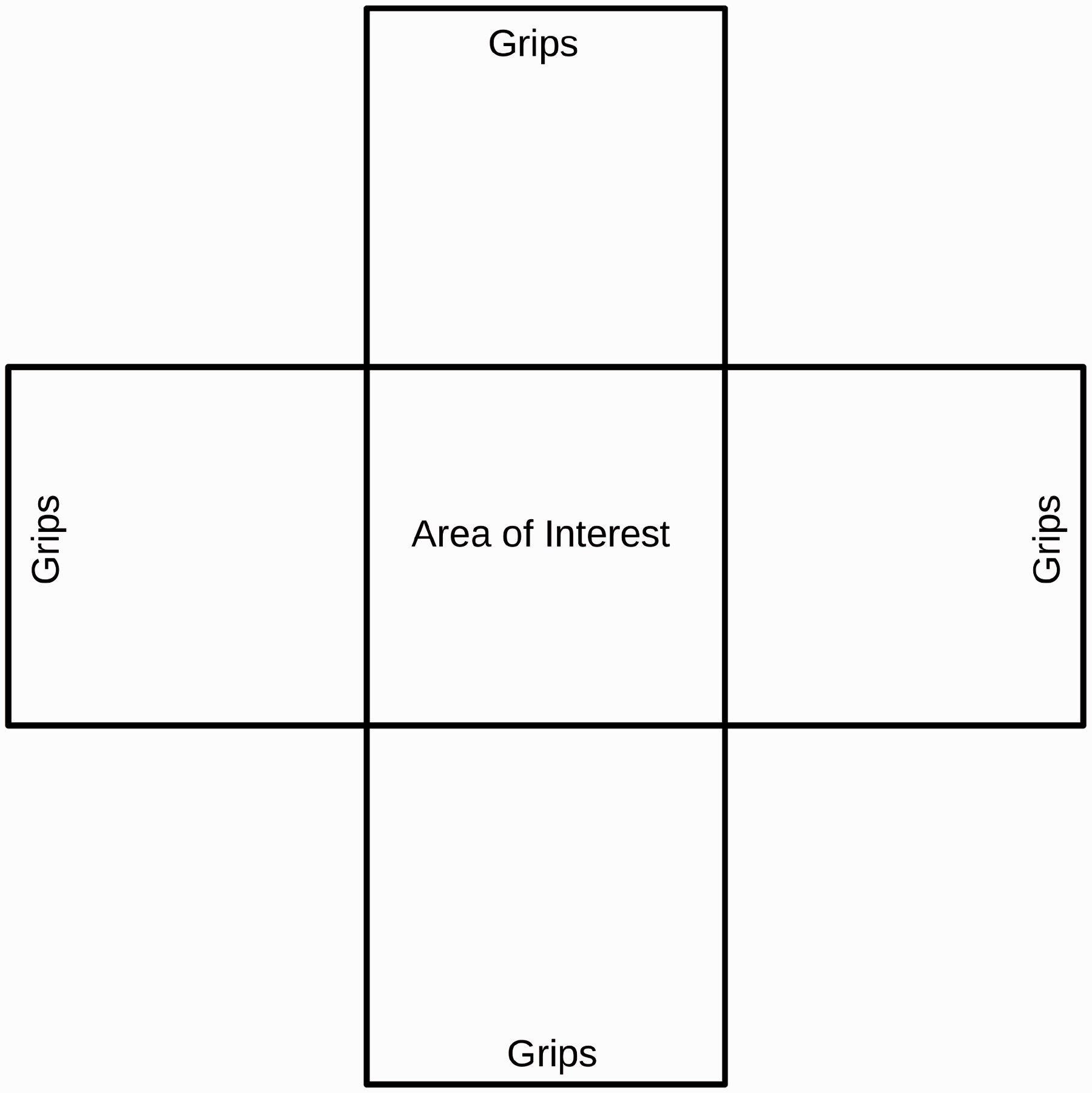
The specimens are lightly preconditioned by shearing the fibres. This frees the tows from each other and is more representative of the material under average use [4]. The specimen is then sprayed with a speckle pattern to provide contrast for the DIC system used to measure the surface strain of the material. DIC was used to capture the full strain field for the 100 × 100 mm2 specimen. To limit the influence of edge effects, only the data from the central 50 × 50 mm2 region of the sample was used in the analysis. The region of interest was chosen to be much larger than the individual fibre tows, so that the detail of individual fibre deformation would not be captured. All DIC measurements were taken using a two camera 3D StrainMaster system supplied by LaVision running DaVis Software [28]. Figure 2 shows a representative specimen mounted in the test frame with an overlay of the material deformation under load.
A representative cruciform specimen mounted to the biaxial tensile test fixture. Specimens are clamped between two plates to prevent slip and two tows are removed to improve the consistency of the results. An overlay is provided showing the magnitude of displacement at each point during a single test measured using DIC. Hot colours represent positive displacements while cool colours represent negative displacements in the measurement coordinate system.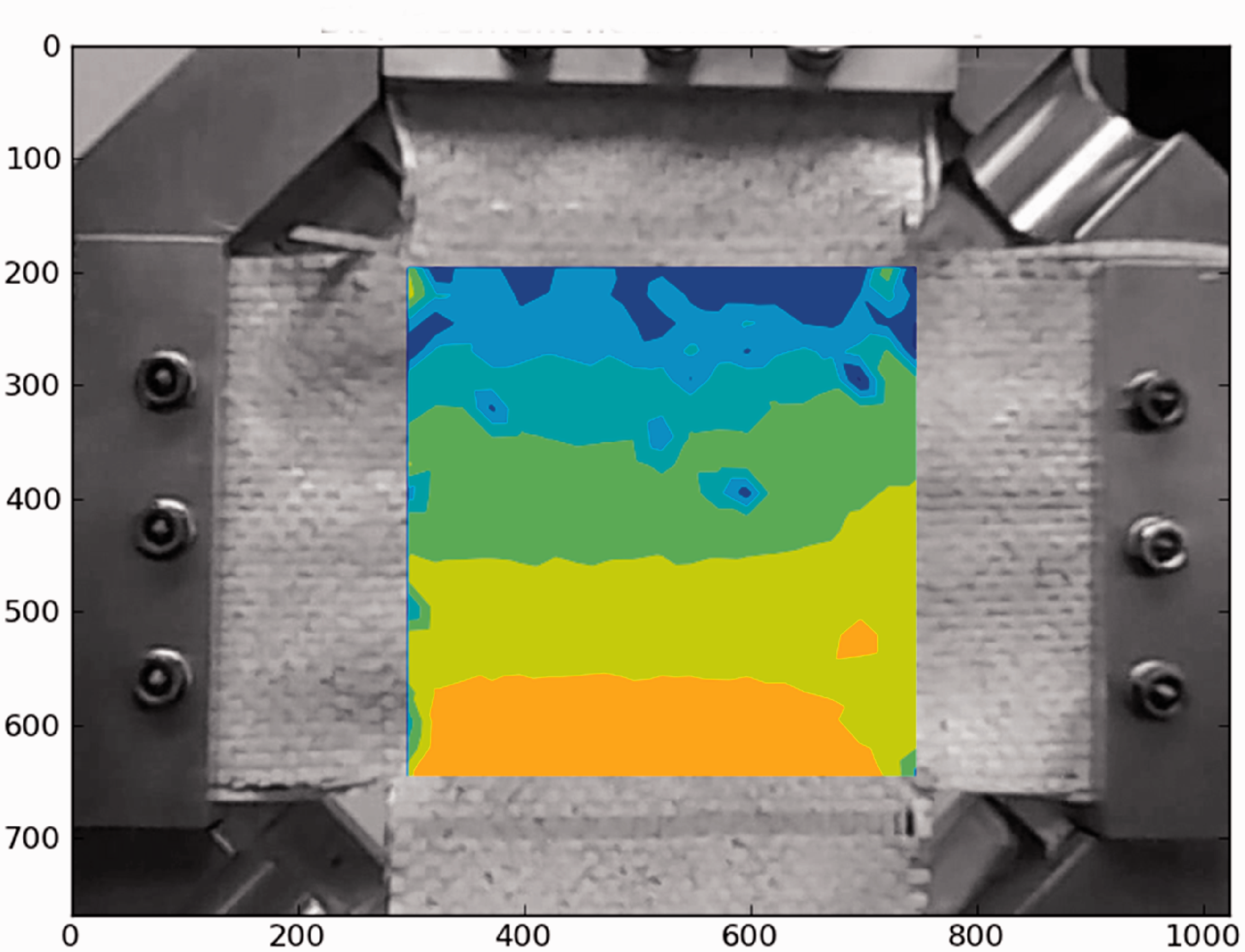
It is the objective of this research to find a suitable representation for a woven textile based on a predefined operational range. The operational range is used to dictate the performance envelope for the material representation that is produced. With this in mind, a predefined material test standard was not used in favour of producing a simple test similar to the load experienced by the material of interest in situ.
Modelling
The literature presented above shows that inverse methods are suitable for homogenisation of materials subject to complex interactions of material and geometric properties. DIC systems can be used to generate displacement field data sets to be matched by a numerical optimiser. A cruciform specimen was subjected to a known boundary displacement and the resulting surface strain was measured using DIC. Representative material models were selected and a replica for the physical test was created as a finite element model. The measured strain in physical testing was enforced in the numerical model as a moving boundary condition. The load–elongation curve from physical testing was then mapped to the numerical model by manipulation of the parameterized material models and minimizing the difference between the two sets of results.
Two material models were selected as likely candidates for investigation from the LS-DYNA material library [29]. An orthotropic elastic plastic model (MAT_108) and a hybrid of existing nonlinear spring and linear elastic membrane models (MAT_S06 and MAT_001). A simple single element model was created for each material model with loads and boundary conditions representative of the centre 50 × 50 mm2 region of the physical test specimen. The results of the simulation are plotted as load-displacement curves in the two material directions. Each of the two models are then parameterized and a numerical optimiser, LS-OPT [30], is used to match the output curves from the numerical model to the resultant curve from the physical test by changing the parameterized values.
Operational strain ranges
The proposed material representations and their calibration rely on the generation of models based on interpolation, it is thus necessary to clearly define the range over which the material will be simulated. Dunnage bags are tested by inflation between two flat parallel plates on a large hydraulic press, constituting a parallel operational void. The prescribed test case requires a bag to be inflated to working pressure and cycled in a parallel void from 305 to 200 mm. Figure 3 shows a dunnage bag loaded into the hydraulic press in preparation for cycled loading. DIC was used to measure the average strain in a region of the bag with a consistent strain gradient that is subjected to high strain. Figure 4 shows the region used for the strain extraction and the full field strain results. The image is taken such that the parallel plates of the hydraulic press are parallel to the top and bottom edges of the image. The left side of the image captures the corner of the bag while the right edge captures the mid-span of the bag. The strain closer to the corner of the bag (left hand edge) is lower than at the mid-span (right hand edge), but the overlay shows higher strains in the left hand region. This region of the bag undergoes large rigid displacements during the test that degrade the fidelity of the results in this area. The hydraulic press inhibits measurement directly at the mid-span.
A representative dunnage bag mounted in the centre of a hydraulic press used for cycled loading. A dunnage bag loaded into the hydraulic press at the apex of a cycled load with first principle engineering strain measured using DIC as an overlay. The left hand edge of the figure shows the vicinity of the stitched seam of the bag while the right hand side shows the mid-span of the bag. A region of consistent strain gradient was chosen near the mid-span of the bag to be representative of the high strain region of the bag this region is indicated by a red box. Hot colours represent high strains while cold colours represent lower strains.

Maximum strain in material warp and weft directions.

Equivalent numerical specimen tests
The equivalent numerical model is a simple four-node unit cell representing a 50 × 50 mm2 patch of material. The assumption is made that there are two perpendicular symmetry planes at the centre of the physical specimen allowing the numerical specimen to be split in four along those two lines. The model for a single shell element is shown in Figure 5, where node 1 is fully constrained and the motions of nodes 2 and 4 are inhibited in the y and x directions, respectively. The numerical specimen is subjected to a forced displacement in the x and y directions matching the maximum weft and warp elongations recorded during the testing of the cruciform specimens, which in turn were based on the elongations measured during the preliminary test of a loaded dunnage bag. A nonlinear analysis is used so in each case the displacement starts at 0 and is increased linearly to the desired maximum value, held for a short time, then returned to the point where the material is no longer loaded avoiding the portion of the simulation that would include wrinkling. For each of the two material representations, the material thickness is taken to be 0.24 mm, which is the average measured thickness of the fabric.
Simple single element model representing a biaxial tensile test. Machine and cross direction load directions are indicated, MD and CD. Node numbers are given as 1 through 4 and the orientation in the simulation coordinate system are given as x and y. Nodes 1, 2 and 4 are pinned: node 1 is unable to translate in either x or y, node 2 may only translate in x and node 4 may only translate in y. Forced displacements are applied to the edges between nodes 2 and 3 and 3 and 4.
The two candidate material models selected make use of different parameters. An orthotropic elastic–plastic material property (MAT_108) is suitable for use with shell elements. In this case, the numerical equivalent model discussed above makes use of only one fully integrated membrane element.
The hybrid spring-shell element equivalent model is similar to that of the orthotropic model, but material stiffness is provided as a series of four nonlinear springs referencing a nonlinear spring property (MAT_S06). The properties of the shell element are selected such that it is compliant relative to the springs, providing little stiffness, but are required for the inflation models used later in full bag simulations. Normally, the combination of stiff and compliant materials would lead to numerical instability; however, since there are no nodes whose displacement depends only on the compliant material, this problem does not arise. The nonlinear springs allow the software user to define separate load and unload curves for each spring. Two springs are calibrated to the warp response, joining nodes 1–4 and 2–3, and two springs are calibrated to match the weft response joining nodes 1–2 and 3–4.
Once the materials have been calibrated, these models are checked for robustness through mesh refinement. A convergence study was performed evaluating the response in terms of reaction force and element stress.
Parameterized orthotropic elastic–plastic material
The orthotropic elastic–plastic material available in LS-DYNA makes use of an anisotropic yield criterion. The model requires two orthotropic elastic moduli to describe the material response before yield and a nominal effective stress versus effective plastic strain curve is required for the post-yield characteristics of the material. Since the two material directions can have slightly different responses, the nominal stress–strain curve is adapted for each material direction by the yield criteria parameters.
The decision was made to use a simple bilinear curve for the nominal effective stress–strain. This was done because the material model calculates stress–strain curves for the weft and warp material directions that are scaled versions of the nominal stress–strain curve. The difference between the two curves is that the onset of plasticity occurs at different points for each direction. Essentially this material model requires that the response curves for both the warp and weft directions must share the same shape profile, which is not the case for this material. If a more complex curve is fitted, the response in one direction can be improved, but the response in the other direction becomes less representative. The warp elongation is much lower than the weft elongation and has a far simpler response over the strain range under investigation. Computational effort was therefore focused on the weft response, which exhibits a more prominent nonlinear plastic response over the operational range of the material.
Material parameters for orthotropic elastic–plastic material model.

Parameterized hybrid spring shell
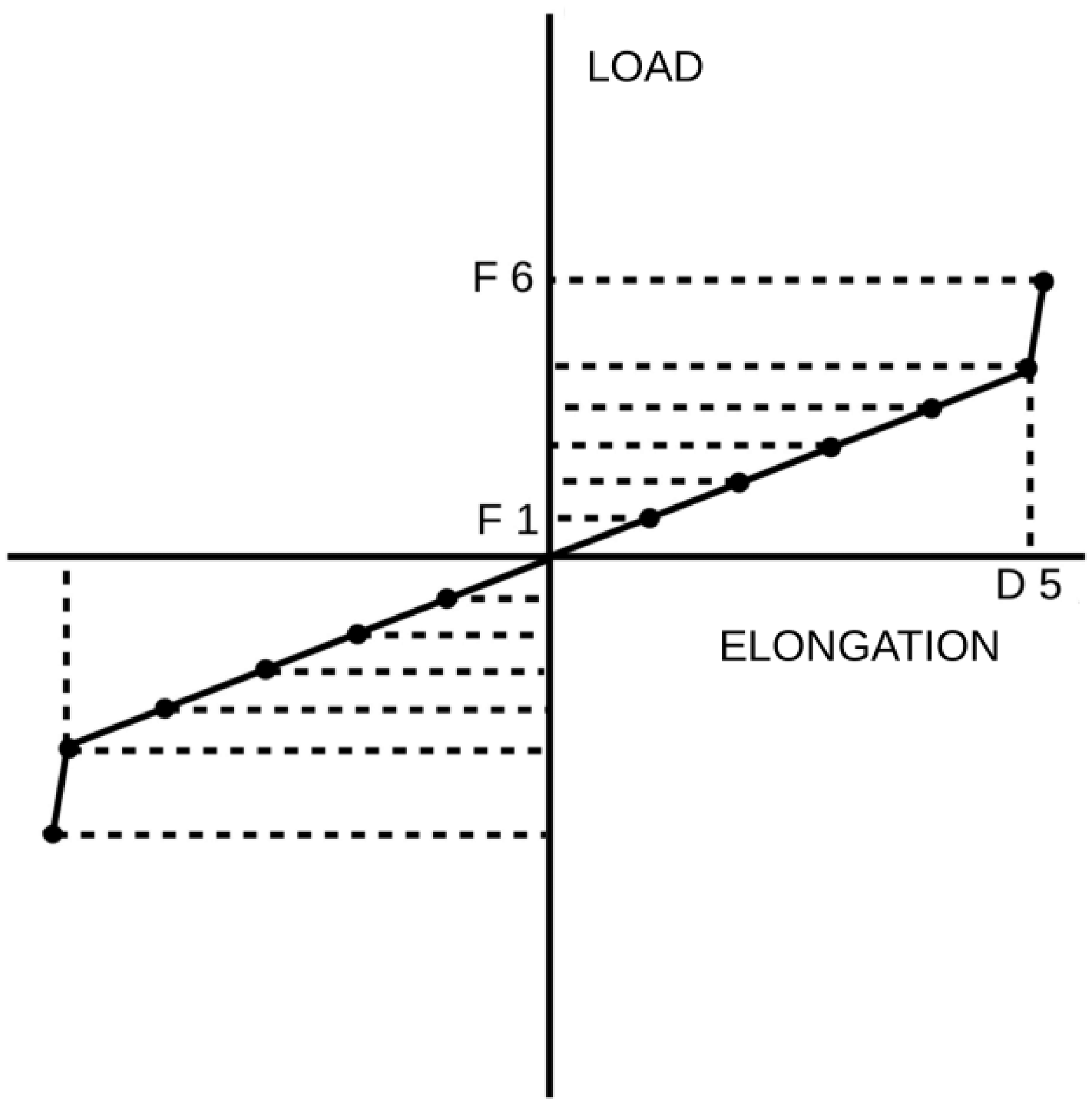
The nonlinear spring in LS-DYNA requires two curves as input, separate load–elongation curves for the loading and unloading of the spring. Since arbitrary load–elongation curves are allowed as input to the spring model, arbitrary load and unload curves can be set for the material warp and weft directions. Figures 6 and 7 show how the load and unload curves for a representative spring have been parameterized.
Generalised load–elongation curve used to define the load characteristic of the general nonlinear spring element (MAT_S06). Eight equally spaced load values (F1–8) and one elongation value (D1) are defined. Generalised unload-elongation curve used to define the unload characteristic of the general nonlinear spring element (MAT_S06). Six equally spaced load values (F1–6) and one elongation value (D5) are defined.
The curve for loading makes use of 10 parameters that define a load–elongation curve, eight force parameters, one elongation parameter and one scale factor for elongation. This is a similar scheme as the one applied to the nominal stress–strain curve of the orthotropic elastic–plastic material model. The load–elongation curve comprises of seven points at fixed elongation intervals and one point where both load and elongation components must be set. This is because the observed material response appears to be somewhat bilinear and there is an advantage to having a point directly at the point of change. The first nine parameters are used to change the shape of the curve and the tenth, the elongation scale factor, is used to stretch the curve to its best fit.
Material parameters for hybrid element material model.

Optimisation of material parameters
An inverse method is used to match the load response of a physical specimen with the response of an equivalent numerical test. This method produces a homogenised equivalent material representation within the bounds of the desired strain range (Figure 8). Specimen tests and simulations are performed, and load–elongation curves are generated.
The flow diagram for the inverse method conducted for material parameter calibration. Preliminary values are provided through a preliminary test, cruciform swatch specimens are tested with load and elongation measured using DIC. These two data sets are used to generate load–elongation (L-E) curves for each test. The measured displacement is used as input for the numerical model boundary conditions. A numerical model using the current material parameter values is run and a load-elongation curve is generated for the simulation. An optimiser then compares the measured and simulated curves and updates the material parameters.
A series of tests were performed on plain woven polypropylene specimens over the strain ranges obtained from the preliminary test. Load and elongation are measured for each specimen in both the warp and weft directions. A load–elongation curve is then generated for the specimens in the warp and weft directions. The measured elongations are then passed as a prescribed displacement boundary condition to a numerical model of the cruciform sample with comparable geometry. The reaction forces required to enforce the defined displacement boundary condition are recorded and summed to generate a load–elongation curve in the warp and weft directions for the simulated test. LS-OPT is then used to minimise the difference between the two load–elongation curves by manipulating the homogenised material parameters.
The inverse problem is stated as minimizing a curve matching metric describing the difference between the load–elongation measured and simulated by changing a vector of design variables that describe the parameterized variables for each material model. The curve matching metric described by Witowski et al. [31] was used to quantify the difference between the two load–elongation curves. This metric was found to be more effective than a conventional sum of squared residuals method, because it is capable of assigning a quantitative difference between two curves that double back on each other. The genetic algorithm available in LS-OPT was used to minimise the difference between the two load–elongation curves.
Results and discussion
A series of cruciform specimens were subjected to a single load–unload cycle with strain ranges defined by the preliminary test. The maximum strain in the bag hoop and longitudinal directions are translated to material weft and warp displacements, respectively. The biaxial tensile test device is set, so that the strain ranges determined during preliminary testing are achieved for the 100 × 100 mm2 area of interest at the centre of the cruciform specimen. Separate load–unload curves are required for the warp and weft directions over only the strain range for that material direction. The tensile test device available can only apply a 1:1 displacement ratio, so two tests were required. Figure 9 shows the load–unload curve for the woven material loaded to the maximum warp strain. Figure 10 shows the load–unload curves for the material loaded to the maximum weft strain.
Measured load–elongation curve for the warp and weft material directions showing a load–unload cycle where the material was elongated to the maximum strain expected for the material warp direction. Measured load–elongation curve for the warp and weft material directions showing a load–unload cycle where the material was elongated to the maximum strain expected for the material weft direction.

The most notable trend observed in the data is that the material weft dominates under low strains while the material warp dominates under higher strains. This trend is not seen with conventional, continuous, homogeneous engineering materials. The transition point, however, occurs outside the expected loading range of the material and thus may not affect the development of numerical material models because the strain ranges in the weft and warp directions are not the same.
It is also observed that even though the test fixture provides a 1:1 displacement control the maximum elongation in the warp and weft direction do not match. For small elongations, the warp tows undergo larger elongations than the weft tows and the reverse is true for large elongations. This is by virtue of the test fixture and cruciform sample. The test fixture provides a 1:1 displacement between its clamps, but measurements are only taken for the 100 × 100 mm2 area of interest in the centre. For each of the arms either only the warp or weft tows provide stiffness. Since the warp and weft tows have significantly different properties the displacement condition applied to the centre 100 × 100 mm2 region will not be the same for the warp and weft directions. This however is not problematic for the proposed method since we simply enforce whatever displacement condition is measured onto the numerical model.
Because of the different strain ranges in the warp and weft directions, the load curve used as the basis for the material parameterisation is a hybrid case using portions of the material load–unload curves from the two single-cycle tests. The warp response will be taken from the maximum warp strain test and the weft response will be taken from the maximum weft strain test. Figure 11 shows the material response curves that will be mapped during the material parameterisation. The curves are scaled to represent a 50 × 50 mm2 specimen.
Measured load–elongation curve for the warp and weft material directions showing a load–unload cycle where the material was elongated to the maximum strain expected for the material warp direction in the warp direction and the maximum strain expected for the material weft direction in the weft direction. The curves here are an assembly of Figures 8 and 9.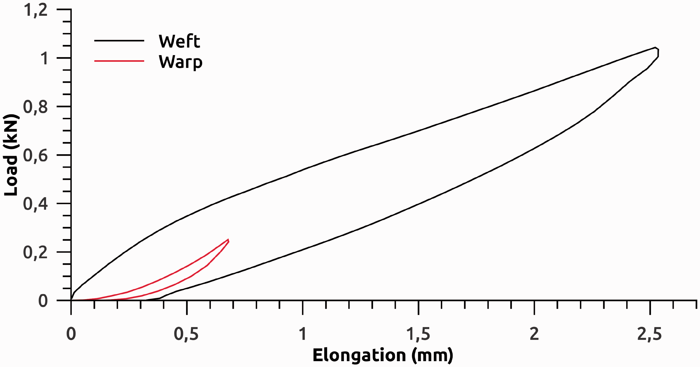
For each of the two material models proposed, the inverse homogenisation described was applied. Figure 12 shows the material response of the 50 × 50 mm2 representative numerical specimen model using the orthotropic elastic–plastic material model to the same displacement profile applied to the physical specimens. The numerical response and the physically tested response differ greatly along the material unload curve, but the numerical material model still largely captures the response of the physical specimen. This model is seen to significantly over-predict plastic strain.
Comparison of the measured and simulated load–elongation curves in the warp and weft material directions for the orthotropic elastic–plastic material.
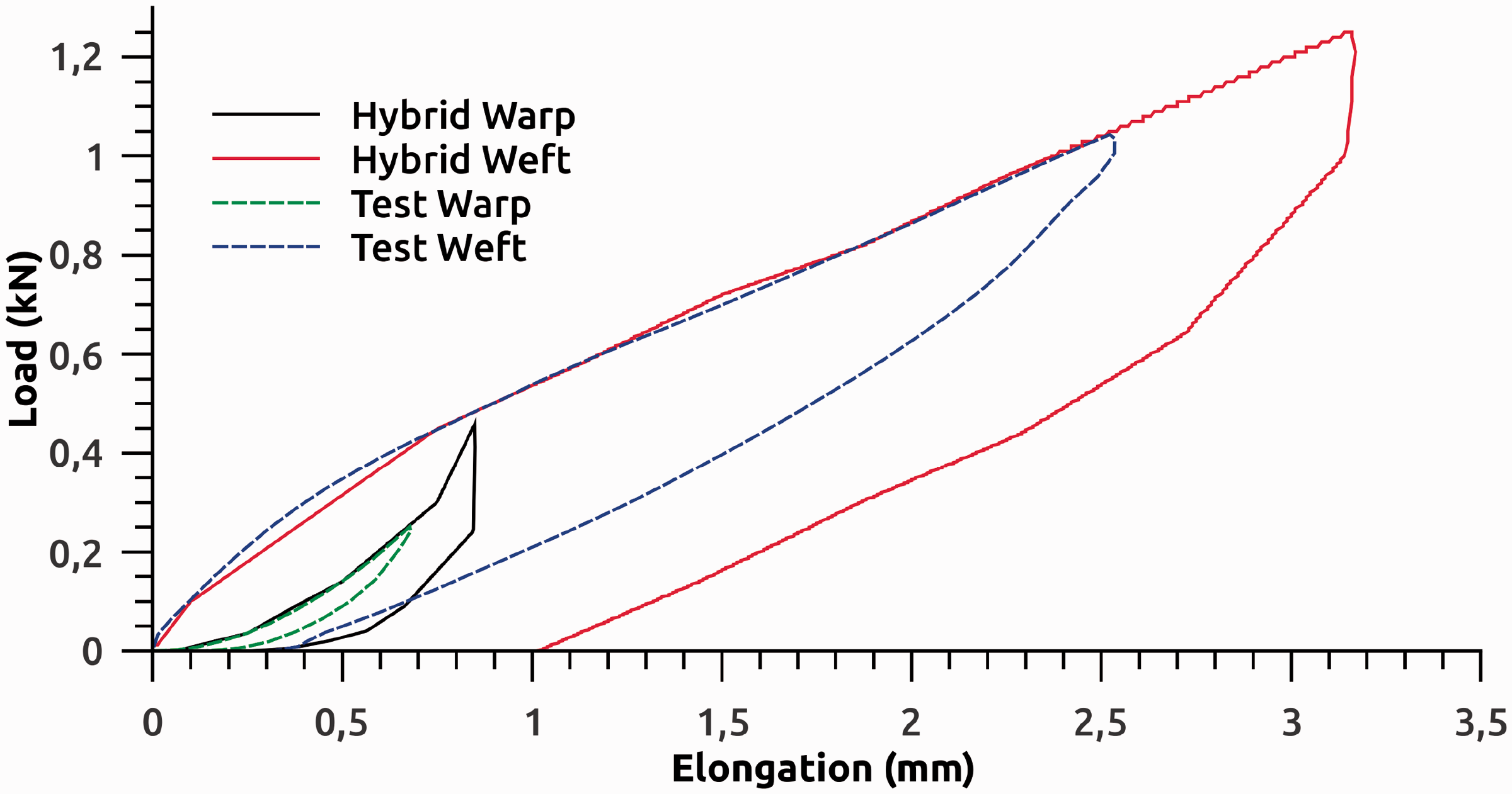
The results generated for the hybrid element material are shown in Figure 13. The material representation captures all key components of the load–elongation curve generated in the biaxial tensile test. Both the load and unload curves have been matched. The model is capable of capturing the different warp and weft trends and the degree of plastic deformation is well captured.
Comparison of the measured and simulated load–elongation curves in the warp and weft material directions for the hybrid spring shell element.
A concern with this type of material representation is that it may only be representative for this single case it was calibrated for. With this in mind, the performance of each model was subjected to a strain 25% larger and smaller that the nominal case used for model calibration. Figures 14 through 17 show the results of these two cases for each material representation. In each case, the behaviour of the model is similar to that of the nominal case and appear to be well behaved. It is further assumed that this meets the requirements of capturing the homogenised response of this material in a full scale simulation.
Comparison of the measured and simulated load–elongation curves in the warp and weft material directions for the orthotropic elastic–plastic material. When the simulated material is subjected to an elongation 25% greater than that at the design point. Comparison of the measured and simulated load–elongation curves in the warp and weft material directions for the orthotropic elastic–plastic material. When the simulated material is subjected to an elongation 25% less than that at the design point. Comparison of the measured and simulated load–elongation curves in the warp and weft material directions for the hybrid spring shell element. When the simulated material is subjected to an elongation 25% greater than that at the design point. Comparison of the measured and simulated load–elongation curves in the warp and weft material directions for the hybrid spring shell element. When the simulated material is subjected to an elongation 25% less than that at the design point.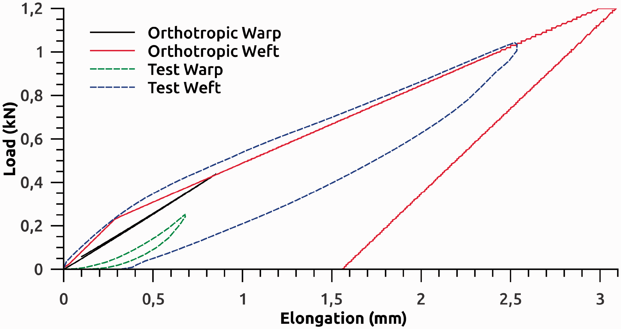


When considering which material model to proceed with, four main items are considered: the accuracy of the material response, the computational requirements of the model, the computational requirement of the model calibration and the robustness of the model.
In terms of accurately replicating the material response, the hybrid element model is superior to that of orthotropic model. The hybrid element model accurately captures both the loading and unloading characteristic of the woven polypropylene material. The orthotropic elastic–plastic model can be adapted in such a way that a more accurate material response can be obtained under loading. For some materials, the material response under loading can be comparably accurate with that of the hybrid element model. The orthotropic elastic–plastic model is however restrictive in its unloading response, and is only capable of a constant slope unload curve, not representative of the curve measured during materials testing.
With regards to both computational requirements and robustness, the orthotropic elastic–plastic model is superior. For a comparable number of elements, a model constructed using the hybrid element material will require on average 10–15 times more time to solve. In terms of robustness, the orthotropic elastic–plastic model has the advantage that the material is the same irrespective of the size and shape of the elements used to construct a bag model. The hybrid element model requires a different load–elongation curve for each element of a different length. In a simple bag model, this can be easily implemented, but if more complex geometries are investigated, or if shape optimisation is attempted, the number of load curves required to define each individual spring will become impractical.
With the accuracy, computational requirement and robustness of the material models in mind, both options should be selected for use depending on the requirement of the final full model. If an accurate unload characteristic is required, then the hybrid element model is required, though the accuracy of the orthotropic elastic–plastic model is reasonable under loading-only cases.
Conclusion
This research has shown that material response of plain woven polypropylene can be accounted for using simple experiments and matching these results to the response of a representative numerical model.
Two material representations were evaluated, a conventional orthotropic material model and a hybrid combination of spring and membrane elements. Both of these representations were implemented in LS-DYNA using only standard material definitions.
Both material representations were parameterized to suitably interface with LS-OPT for parameter calibration. An inverse method was used to map the load response results from a simple biaxial tensile test to the two parameterized material representations.
The method proposed does not consider the fibre level interactions and does not attempt to define a generic material model for this class of material, instead a method is proposed that produces an equivalent homogenised material that responds in the same manner as the woven fabric over a predetermined range. The material was also investigated for its response at loads around its design envelope and found to reasonably represent the material.
It was found that the calibrated orthotropic elastic–plastic material model was suitable for capturing the response of plain woven polypropylene under continuous loading but failed to capture the unloading of the same material sample. The model was also not well suited to capturing the vastly different load responses of the warp and weft fibres.
The hybrid spring shell material captured the loading phase of the material at least as well as the orthotropic model but goes further in its ability to capture the warp and weft responses simultaneously. In addition, this model was able to capture the unloading response of woven polypropylene in both the warp and weft directions.
This research shows that reasonable simulations can be performed of woven fabrics with complex material responses without the need for computationally intensive material models or testing if the scope and range of material responses is well defined.
Footnotes
Declaration of Conflicting Interests
The author(s) declared no potential conflicts of interest with respect to the research, authorship, and/or publication of this article.
Funding
The author(s) received no financial support for the research, authorship, and/or publication of this article.