
Abstract
The principal component of any non-invasive blood pressure measurement system is an inflatable cuff. Different types of fabrics are used for inflatable cuffs construction. In this study, sphygmomanometric blood pressure measurement using inflatable cuffs was simulated in Abaqus and validated through experimental results. The purpose of the simulation is to study the effect of variation in cuff fabric geometric and mechanical properties on pressure distribution and pressure transmission during blood pressure measurement by predicting the pressure at the interface of the blood pressure cuffs and a metal cylinder. Geometric and mechanical properties of the fabrics of four different cuff types were found experimentally. Interface pressure at the cuffs and metal cylinder surface was also found experimentally using Tekscan pressure sensing system for models validation. The results of the simulation showed that the interface pressure underneath the cuffs vary with variation in geometric and mechanical properties of their fabrics. The results of the simulation were found to be in good agreement with experimental findings. This research demonstrates that the pressure distribution under the cuffs is related to the cuffs' fabric geometric and mechanical properties. This means that variation in cuffs' fabric properties could ultimately incur variations in the blood pressure values of human subjects.
Keywords
Introduction
After body temperature, pulse rate and blood pressure (BP) are the physiological parameters most frequently measured in clinical practice. Non-invasive BP measurement using an occluding cuff is one of the most frequently undertaken medical tests, especially because it avoids direct arterial cannulation. Indirect assessment of the BP was introduced by Karl Vierordt in 1854 with the invention of the sphygmograph. Scipione Riva-Rocci invented inflatable rubber cuff in 1896 for non-invasive BP measurement [1]. The main condition is the complete occlusion of blood flow in an artery of a limb under a pressurized cuff. A sphygmomanometer cuff is inflated above systolic BP after wrapping around the limb and then deflated. Manometric pressure at which blood flow resumes during the cuff deflation is considered same as arterial systolic BP. The first stage of the pressure transmission is its propagations from surface of the cuff to the surface of the arm, i.e. at the interface of cuff and arm during BP measurement. However, the pressure registered by the manometer is a pressure in the inflated cuff, which is enclosed between the cuff's layers. This is only known pressure in this system. The pressure exerts by the BP cuff on the arm surface i.e. the interface pressure (IP) which tranmits to the arterial wall (arterial pressure) is unknown during BP measurement using non-invasive techniques.
A wide range of cuffs are used all over the world every day. Cuffs available worldwide differ in terms of types, construction material and closure mechanism. BP cuffs can be classified in different manners as those with or without an inner bladder (bladdered or bladderless), or with the number of bladders inside the sleeve i.e. single cuffs, double cuffs and the TriCuff® [2–4].
BP cuffs are generally constructed from coated (air impermeable) woven or non-woven fabrics. The coated fabrics are also termed as the flexible composite which comprise textile base and polymeric coating. The physical properties of the coated fabric depend on the substrate properties, coating formulation and coating technique [5].
Types of Blood Pressure cuffs
1a. Single cuff with bladder
Single cuff with bladder have been widely used for more than a century. It is an assembly of an external sleeve containing an inflatable bladder as shown in Figure 1(a and b). It comprises of:
(a) Single cuff with fabric bladder (b) Single cuff with rubber bladder.

To construct the cuff sleeve and the bladder, the fabric is usually stitched or fused by employing 100% radio frequency welding. A conduit for the supply of pressurized air is attached to the inflatable bladder. In majority of the BP cuffs a strip of the Velcro is either stitched or pasted over the outer surface of the sleeve to fasten the cuff securely during BP measurement. Mostly nylon-coated with urethane or polyester fabric is used to manufacture BP cuff sleeve and bladder to make it air impermeable [3].
1b. Single cuff without bladder
In bladderless cuffs, one portion of the sleeve is made inflatable whilst the same sleeve also facilitates closure once is wrapped around the limb as shown in Figure 2. These cuffs could be reusable or disposable. Bladderless cuffs, reusable and disposable are manufactured using the coated, woven and non-woven fabrics, respectively.
Single cuff bladderless.
It is important to know the effect of different types of construction material on measurement of BP which could be directly related to the accuracy of BP measurement. Accurate classification of a person's BP level requires the measurement to be independent of type of cuffs used. This study covers the cuffs used to measure BP by the auscultatory method. In the types of the cuffs outlined above, four single cuff without bladder are selected for this investigation. The effect of the varying cuff fabric construction on sub-cuff pressure has not been studied in detail in previous investigations [7–9]. In this study, variation in cuff construction is investigated by determining the mechanical and geometric properties of cuff fabric by standard test methods so that pressure distribution underneath the cuffs, over the rigid metal cylinder could be predicted accurately.
The importance of the IP measurement has been recognized in the studies related to the decubitus ulcer, pressure ulcer / sores formation, pressure garments and burn garment, human and animal comfort, pressure ulcer development and its treatment [10–14]. IP was measured for the pressure ulcers treatment, footwear fitting, burns treatment, venous ulcers and orthotic diseases to anticipate the susceptibility of the ulcer development and its management. The measurement of the IP for the wheelchair users has become an essential activity with increase in litigation [14].
Direct arterial pressure cannot be determined using inflatable cuffs. Measurement of the pressure at the interface of BP cuffs and arm may play an important role for the estimation of the correct BP.
Pressure measurement at the interface of human upper arm and different cuff types could not be easily carried out because of the degree of discomfort entailed in obtaining numerous repetitive readings requirements, need for proper training and ethical approval. It is imperative to find whether the IP variations under the different cuff types can be predicted through simulation. In this study, 3D finite element (FE) modelling was done in Abaqus 6.10-1 [15] to predict pressure at the interface of different types of BP cuffs of identical size and a bare metal cylinder. Size of the cuffs was selected according to the circumference of the metal cylinder following standard guidelines of British Hypertension Society [6].
Four FE models were developed in Abaqus for the prediction of pressure at the interface of the BP cuffs and the metal cylinder. Pressure of 18.665 kPa (140 mmHg) was applied inside the cuffs and then removed completely, same as that of standard guidelines of BP measurement [6]. The IPs predicted in all models were recorded for visual and numerical analysis. It helped identifying the variation in pressure underneath different cuffs types. For numerical models validation, IP was measured using an in-vitro system by employing TekScan Interface pressure sensing system [10].
Material and method
Material properties
Specifications of the bladderless cuffs.

The metal cylinder is a rigid object that is made from steel. Material linearity and geometric non-linearity were selected in the proposed FE models. The mechanical characteristics of the metal cylinder were kept fixed under each cuff type in order to predict the effect of the variations in cuff's geometric and mechanical properties solely on the pressure distribution underneath them.
Development of models for Finite Element Analysis
BP cuffs and metal cylinder
The 3D bladderless cuffs were developed in Abaqus. Dimensions of the cuffs were kept as per original cuffs. All bladderless cuffs were comprised of two walls same as that of bladderless BP measurement cuffs. The cuff walls were developed in such a way so that length of the cuffs covered 80% arm circumference as per standard recommendations of British Hypertension Society [6]. The loaded and unloaded surfaces are shown in Figure 3. The pressure was only applied in loaded surface to follow 80% rule as mentioned above.
Bladderless cuff walls (a) Innerwall (b) Outerwall.
A circular solid homogenous steel cylinder was developed to have a length and circumference of 40 cm and 42 cm, respectively. Due to the higher degree of rigidity, there was no deformation in the steel cylinder upon applying pressure of 140 mmHg.
Properties were assigned to cuffs and metal cylinder. The cuff and the metal cylinder were assembled then. Surface-to-surface contact and tie constrain were applied between the surfaces of the cuffs and metal cylinder. In all models, a small sliding was applied with the help of penalty method in order to allow sliding friction between the contact surfaces. Auto-stabilization was implemented for the contact control during the analysis.
Pressure was applied inside the cuffs in all FE models with amplitude to account for the cuff inflation followed by the deflation. Pressure was increased from zero mmHg to 140 mmHg (18.665 kPa) and then descended back to zero mmHg.
A metal cylinder showed no deformation and maintained constant dimensions throughout the simulation so the displacement was fully constrained. The horizontal displacement of the cuff's walls was constrained only to allow the translational motion in the rest of the directions.
Cuffs were meshed with hexahedral, 3D stress configuration, while metal cylinder was meshed with tetrahedral, 3D stress approximation as shown in Figure 4. After meshing, non-linear static general analysis was performed.
Cuff-metal model after meshing.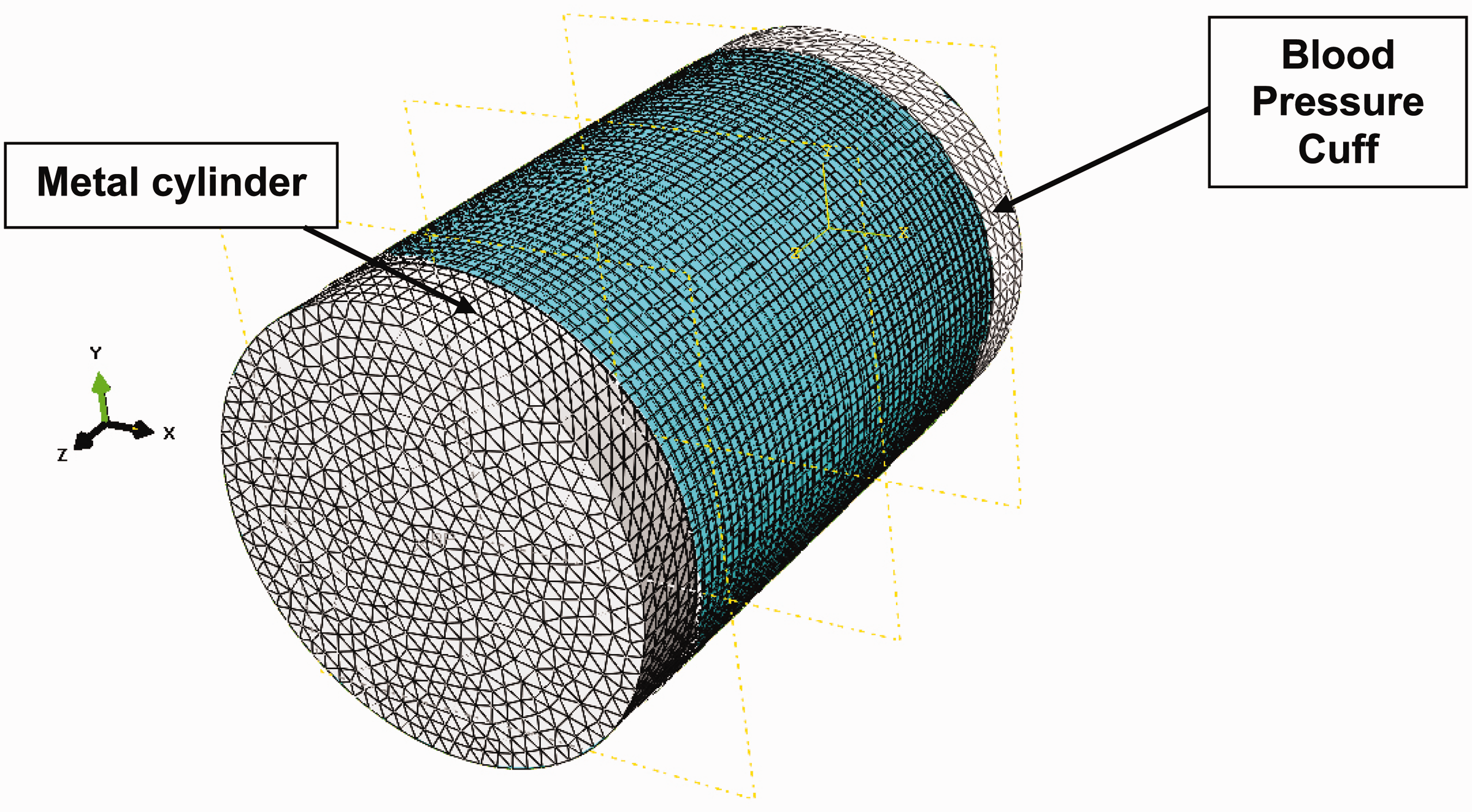
Experimental work to validate models for Finite Element Analysis
Experimental setup for the validation of models is shown in Figure 5. Tekscan Industrial sensing system (I-Scan) is an advanced pressure distribution measurement system employed to map the pressure at the interface of the BP cuffs and the metal cylinder. Tekscan sensor consists of sensils that are arranged in an array of 16 × 6, as shown in Figure 5. The selected steel cylinder was of the same size as that of steel cylinder built in the Abaqus for FEA. Cuffs of size adult arm (following standard guidelines of 80% rule) were wrapped around metal cylinder so that the centre of each cuff remained over the centre of Tekscan sensor as shown in Figure 5. The IP was measured in real time against the pressure inside the cuff by inflating it directly to 140 mmHg followed by stepwise deflation. IP was recorded at a regular interval of 20 mmHg during deflation from 140 mmHg to zero mmHg. All the measurements were repeated five times under each cuff.
Experimental setup to measure pressure at the interface of BP cuff and metal cylinder.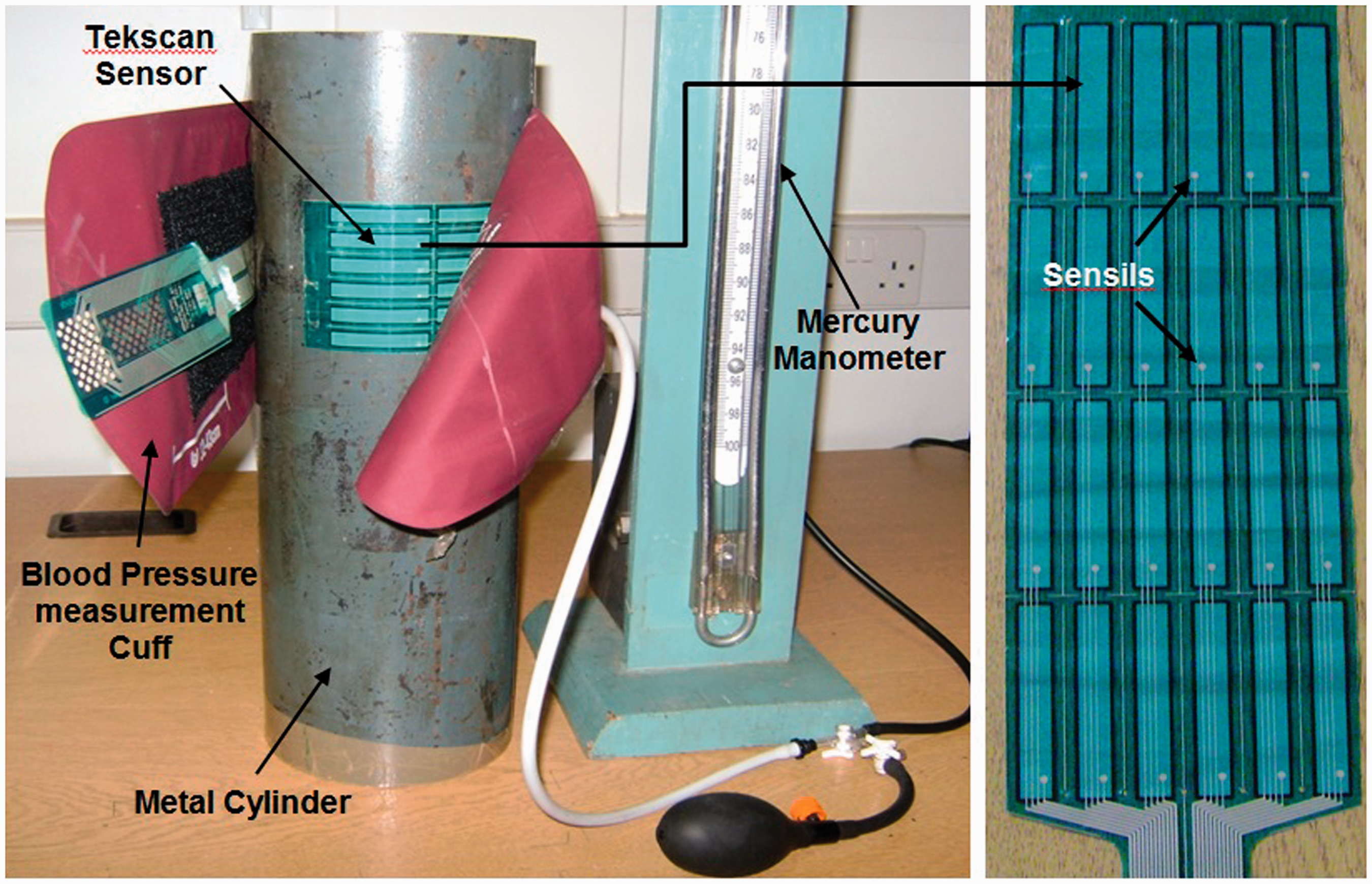
Results
The IP distribution over the metal cylinder surface, resulted after post-processing of the FE models, is shown in Figure 6.
Interface pressure distribution on the surface of metal cylinder against 140 mmHg 
The results showed that the IP under the selected cuffs is not identical. It can be seen that the pressure under Cuffs A, B and D is uniformly distributed. These BP cuffs are made of woven fabrics and the values of their elastic modulus are higher than Cuff C which is constructed from non-woven fabric and has the lowest value of elastic modulus. It indicates that the cuff with higher modulus of elasticity and constructed from woven fabrics may distribute uniform pressure around the arm. The pressure distribution under Cuff C is non-uniform. The cuff fabric is non-woven and has the highest value of thickness and the lowest value of elastic modulus. It shows that there may be also an impact of fabric thickness on the deformation of the cuff walls and ultimately on the pressure distribution underneath.
For the validation of the models, the IP was averaged at four nodes, selected over the metal cylinder surface at three different positions (designated as positions X, Y and Z), see Figure 7. The results were plotted during cuff deflation only because mostly in auscultation, the BP is estimated during cuff deflation. From the experimental investigation, the IP values were taken from the sensils at the corresponding positions X, Y and Z on the metal cylinder and then averaged. For the validation of models, measured and predicted IP are provided for the position Y (centre) only, of all the cuffs selected for this study. For the positions (X and Z), measured and predicted IPs are plotted only for Cuff C (see Figure 8).
Nodes selection over metal cylinder surface. Interface pressure during cuff deflation.

% Error for numerical and experimental data for Cuff A model.
% Error for numerical and experimental data for Cuff B model.

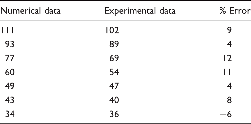
% Error between numerical and experimental data for Cuff C.

% Error for numerical and experimental data for Cuff D model.

Discussion
The detailed models of the different types of bladderless cuffs are presented while simulating the phenomena of BP measurement using a bare metal cylinder. Models with such details have not been developed before. The construction of the cuffs in the models was kept same as that of the original cuffs. The properties of the cuffs' fabrics were determined without considering the characteristics of the underlying material to avoid the impact of the specific object density with respect to the properties of cuffs' fabrics so that the models would be able to predict pressure distribution accurately.
The models aided in identifying the areas of high and low pressure under a particular cuff through visualization which is difficult to identify during the experimental investigation. One of the most important finding was that the region where a cuff should apply the maximum pressure was not at the middle of the cuff, i.e. artery index. The Brachial artery is located underneath this region and BP cuffs are supposed to apply higher pressure at this region instead of the other points for complete occulation of brachial artery. It indicates one of the design faults associated to the commercially available BP cuffs. It is also important to know the impact of sub-cuff pressure variations on the arterial pressure as it is the main area of interest during BP measurement.
As indicated in the results, the pressure distribution under a cuff depends on the types of fabric employed for its construction (woven or non-woven) and associated properties (see Table 1).
It is important to note that there is no deformation in the metal cylinder during IP measurement and results only depicted the variation in the results due to the variations in the cuff's fabric properties. The difference among pressure distribution under cuffs of different types may be related to the difference in their deformation which is due to the variations in the thickness and elastic modulus. It is reported that the biomechanical functional performance of devices depends on the fabric's mechanical properties, which can be determined by the constituting yarns and internal structural features [16]. During the inflation and deflation, the cuff walls deform, which depends on its properties. Considering the IP found experimentally against 120 mmHg cuff pressure, Results show that the cuff C whose fabric have the lowest value of elastic modulus and the highest value of thickness amongst; applied 102 mmHg pressure over metal cylinder. While Cuff B constructed from a fabric having the highest value of elastic modulus and the thickness is lower than Cuff C fabric thickness; applied 98 mmHg over the metal cylinder surface. The highest value of IP is found under Cuff D and the lowest value is under Cuff A. It depicts that pressure applied by cuffs over the metal cylinder varied with variation in the elastic modulus and the thickness of their construction material (see Figure 8).
The validation of the models from the experimental data (Figure 8 and Tables 2 to 5) showed that it is possible to predict the pressure transmission under the cuffs of different types over the metal cylinder. It is shown in Figure 6 that the pressure distribution under the cuffs over the metal cylinder surface varied under the BP cuffs with change of their mechanical and geometric properties. The variations will be more in the pressure transmission to the brachial artery if measured on the human subjects underneath the different types of BP cuffs. Tissues of human arm are more compliant compared to the metal cylinder and deform during BP measurement which may show more variation in IP values and hence the BP values measured using BP cuffs of different types.
Measurement of IP could be a good predictor of the value of the pressure occludes artery i.e. arterial pressure and may eliminate the inaccuracies associated to the indirect measurement of BP using cuffs [17–22]. As a result, a study has been carried out as a subsequent research on artificial human arm having same mechanical and geometric properties as that of real human arm to find effects of variation in cuff mechanical and geometric properties on BP measurement.
If the pressure at the interface of the cuff and the arm is known, then there could be a possibility of the estimation of accurate BP measurement through indirect techniques with the help of simulation.
The values of the interface pressure between the arm surface and BP cuff can be predicted through FEA. If the IP is either higher or lower than the value of pressure inside the BP cuff, so it may also indicate the value of the pressure transmits to the artery during BP measurement. The higher value of pressure at the interface by a particular cuff might stop blood flow through the artery earlier than the cuff applied the lower pressure over the surface of the arm. It may lead to the variation in BP values if measured by cuffs of different types.
This study demonstrates that it is now possible to predict pressure transfer underneath a particular cuff prior to the construction. It may also aid in identifying the appropriate geometric and mechanical properties of the cuffs' fabrics for desired pressure transfer for arterial occlusion during BP measurement. Therefore, it will be imperative to evaluate the effect of IP variations on the blood pressure on the human subjects in future studies. It can be inferred from the results that variation in the geometrical and mechanical properties of BP cuffs fabric could affect the accuracy of BP measurement using indirect techniques involving inflatable cuffs.
Conclusion
This study demonstrates that the different types of blood pressure cuffs are unable to deliver identical value of pressure underneath owing to the fact that interface pressure under a particular cuff depends on the geometric and mechanical properties of the fabric, used for its construction. Results also showed that the variations in the interface pressure under different types of cuffs depend on the fabric types i.e. woven or non-woven techniques. Validation of the models from the experimental data shows that it is possible to predict the interface pressure distribution under blood pressure cuffs of different types through a detailed Finite Element Analysis. It would also be possible to predict the blood pressure of human subjects through Finite Element Analysis under a cuff of any type.
In order to remove inaccuracies in the currently available blood pressure measurement cuffs, it is important to standardize mechanical and geometric properties of the fabrics used for blood pressure cuffs construction. This study asserts that a new blood pressure cuff needs to be designed which applies known value of pressure over the arm and then onto the artery for accurate estimation of blood pressure.
Footnotes
Declaration of Conflicting Interests
The author(s) declared no potential conflicts of interest with respect to the research, authorship, and/or publication of this article.
Funding
The author(s) disclosed receipt of the following financial support for the research, authorship, and/or publication of this article:The authors would like to acknowledge the funding provided by the NED University of Engineering & Technology Pakistan, through the Higher Education Commission of Pakistan, to carry out this study at the School of Materials, The University of Manchester, UK.