
Abstract
Composites with different arrangements of continuous carbon fibers, with the poly(ethylene terephthalate)-spunbond nonwoven fabrics as substrates, were fabricated for optimization of electromagnetic interference shielding performance. Effects of these structural parameters, including array spacing, the number of layers, and overlap angle, were investigated within the frequency band of 30 MHz–1.5 GHz, which includes the major electromagnetic wave frequency from daily electronic device or apparatus. Within 30 MHz–750 MHz, shielding effectiveness was fortified with the decrease of array spacing and the increase of the number of layers owning to the increase of the continuous carbon fiber content. Whereas, within the frequency band of 750 MHz–1.5 GHz, the number of layers presented little effect on the shielding performance reasoning that the impact of continuous carbon fiber orientation was more significant than that of continuous carbon fiber content. While the array spacing was 8 mm and the maximum value of shielding effectiveness for the two-layer composites was 46.8 decibel at frequency of 1000 MHz. For multilayer composites, shielding performance was improved by synergistic effects of overlap angle and array spacing. Hence, composite with three layers, array spacing of 12 mm and overlap angle of 0°–0°–45° achieved the highest electromagnetic interference shielding properties of 60.49 decibel, corresponding frequency of 1.0 GHz. The results of this work demonstrated a potentially efficient and economical way to fabricate the electromagnetic interference shielding composites with less content of continuous carbon fiber and to simultaneously achieve superb shielding performance. This work will be significant for further study in the electromagnetic interference shielding composite industry in the near future.
Keywords
Introduction
Electromagnetic interference (EMI) is a conducted and/or radiated electromagnetic signal. The source of the electromagnetic signal comes from any device or apparatus that transmits, distributes, processes, or utilizes any form of electrical energy. The EMI may react with any electronic devices to degrade the performance of other equipment, or systems in the same environment [1]. In the last 50 years, man-made electromagnetic energy leaking into the environment has grown exponentially. Although this leaked electromagnetic energy is not intentional, it still causes a series of serious interferences to the environment and human body. EMI shielding materials have gained a great importance due to their practical application in electronic, aerospace, medical, and military devices to shield electromagnetic radiations emitted from nearby devices. EMI shielding is needed for protecting electronics, avoiding unauthorized surveillance and deterring electromagnetic forms of spying in this modern society, as the commercial, military, and scientific electronic devices and communication instruments are used more and more widely.
Originally, various types of metal and their compound exhibiting high conductivity and dielectric constant were widely used to shield electrical circuits by reflection since the Faraday cage effect was found more than two centuries ago [2]. However, there are some limitations associated with metallic sheets due to their high density, high stiffness, expensive processing, and prone to oxidation [3]. Compared to conventional metal-based EMI shielding materials, conductive polymer composites have been extensively investigated in an attempt to overcome the drawbacks of metal-based EMI shielding materials [4,5]. In particular, polymer composites containing carbon-based fillers (e.g., graphite (G) [6,7], carbon black [8], carbon fibers [9,10], carbon nanotubes [11,12] have been extensively investigated for use as EMI shielding owing to their unique combination of electrical conduction, polymeric flexibility, and lightweight [13–15]. Especially, due to the excellent properties of low density, high strength, high modulus, corrosion resisting and great flexibility, carbon fibers have obtained more interest as fillers to fabricate EMI shielding composites in recent decades [16–18]. Due to the high electrical conductivity provided by the continuous carbon fiber (CCF), high shielding effectiveness (SE) is exhibited by CCF polymer-matrix and carbon-matrix composites [19]. The effectiveness is higher for carbon-matrix composites than the corresponding polymer-matrix composites, due to the conductivity of the carbon-matrix [20].
Composites filled with short discontinuous carbon fibers can form a three-dimensional efficiently conductive network by internally overlapping the polymer-matrix composites, with the prerequisite of ideal dispersion for excellent EMI shielding performance. However, it is rather difficult to achieve perfect dispersion with this kind of fillers [21]. Jou [14] has used the woven CCF to fabricate a predesigned conductive CCF network, which achieved great dispersion and reduced the content of the CCF obviously. The EMI shielding performance of this composite was remarkably improved. Since the orientation patterns influence the transmission and reflection properties of the composite materials greatly, the CCF composites are woven in predesigned patterns to provide a continuously conductive network before being laminated into composites [22]. Nevertheless, further study of the effects of arrangement of CCF in composites on the EMI shielding performance is still needed.
In this study, the CCF was arranged on the poly(ethylene terephthalate) (PET)-spunbond nonwoven fabric substrates with different orientations and array spacings using the measure tools and position tools to ensure the accuracy in spacing and angle. There is specific spacing between the CCF filament bundles for the certain EMI shielding performance. It will be economical process of the preparation of the composites. The CCF was arranged directly on the PET-spunbond nonwoven substrates without any interweave up and down. It can theoretically increase the strength utilization of the carbon fibers. Meanwhile, the abrasion of CCF during weaving has been avoided. Then the impacts of different arrangements of the CCF in composites on the EMI shielding performance, such as array spacing, the number of layers, overlap angle between layers, are investigated, respectively, for the preparation of the CCF composites with excellent EMI shielding performance. This can be the potential advantage to apply the CCF to the EMI shielding composites industry economically.
Experimental
Materials
The CCF filament bundles with specification of 12K and linear density of 115 tex were kindly provided by Yixing Hongyu carbon fiber composite materials technology co., Ltd. PET-spunbond nonwoven fabric with surface density for 42.98 g/m2 was from Hangzhou golden lily nonwovens co., Ltd. Acrylic adhesive was provided by Wuxi LanChen adhesive products co., Ltd.
Preparation of samples
The polymer-matrix composites of the CCF were prepared by the specific processes as follow:
Step 1: The CCF filament bundles were laid parallel along the warp direction at equal intervals (i.e., 2 mm, 4 mm, 6 mm, 8 mm, 10 mm, 12 mm, 14 mm, 16 mm, 18 mm, and 20 mm, respectively) on PET-spunbond nonwovens using the measuring tools and positioning tools, then cemented by the acrylic adhesive. Step 2: On the basis of step 1, carbon filament bundles were laid parallel along weft direction at equal intervals just as that in step 1. Then, another piece of PET-spunbond nonwovens was added to the upper of the carbon fibers laid. Then the single-layer composites based on grid-type carbon fibers were completed. And the thickness of the single layer was around 0.67 mm, with an error of ±0.005 mm. Step 3: The two-layer and three-layer samples were prepared by combination of the single-layer samples in step 2 at the same interval among different layers. The specific parameters of the samples with different patterns were shown in Table 1. Step 4: In order to facilitate subsequent performance tests, the samples should be tailored to circular samples with a diameter of 115 mm finally. Permutation and combination between the two-layer and three-layer samples.

As shown in Figure 1, all the prepared samples are smooth and uniform for the one-, two-, or three layers. The adhesion of the CCF on the PET-spunbond nonwoven substrates was assessed qualitatively by shaking and dropping the samples several times and followed by bending the samples. The CCF still adhered to the substrate because of the flexible nonwoven substrate even after bending process.
The images of the fabricated composite samples.
Permutation and combination way between layers
The influences of different arrangements of CCF in polymer-matrix composites on EMI shielding performance were observed according to standard, “SJ20524-1995 the shielding effectiveness measurement for materials” [22,23]. Table 1 presented the permutation and combination way between two-layer and three-layer samples. The data in Table 1 represented rotation angles of the single layer of samples. Those data from top to bottom were corresponding to those of first-layer, second-layer and third-layer ones, respectively. The arrangements of CCF for three-layer samples only use (a) 0°–0°–0°; (b) 45°–0°–0°; (c) 0°–45°–0°; (d) 0°–0°–45, and not use 90° as the basis to evaluate EMI shielding performance, for the reason that samples using 90° is same as that using 0°–0°–0° due to the vertical relationship between the CCF on the weft direction and those on the warp direction in each single layer.
Overlap angle between layers of carbon fibers in two-layer samples was shown in Figure 2. And Figure 3 showed the overlap angle between layers of carbon fibers in three-layer samples.
The schematic diagram of arrangements of CCF for two-layer samples: the samples with the overlap angle 0° (a) and 45° (b) between the first layer and second layer. The schematic diagram of arrangements of CCF for three-layer samples: (a) 0°–0°–0°; (b) 45°–0°–0°; (c) 0°–45°–0°; (d) 0°–0°–45. These data from top to bottom were corresponding to those of first-layer, second-layer, and third-layer ones, respectively.

Testing and characterization
Measurement of EMI SE
The EMI shielding performance of samples was measured by a Vector Network Analyzer (E5061A, Agilent Technologies) coupled with a coaxial test device (DN1015 A, EMC Lab of Dongnan University) for material far-field SE within the frequency range of 30 MHz–1.5 GHz, which includes the major electromagnetic wave frequency from any daily electronic device or apparatus such as computers, mobile phones, microwave ovens. Each sample was tested in triplicate, and the average data was analyzed.
EMI shielding theory
The spectrum of electromagnetic radiation consists of waves with electric and magnetic components oscillating at right angles to each other. The electromagnetic shielding is a process of limiting the flow of electromagnetic fields between two locations, by separating them with a barrier made from conductive materials [15,24]. SE is an important parameter to measure the shielding of a device from EMI. The higher the value of SE in decibel (dB) is, the less the electromagnetic energy that penetrates through the sample is.
An electromagnetic wave can be attenuated by the absorption (A) and multi-reflections (B) inside the materials, as well as the reflection (R) from the outer surface. The SE is the sum total of these three sections. If the incident power density is denoted by Pinc; transmitted power density by Ptrans, then the SE is given by the equation (1) [23].

Results and discussion
The structural parameters for polymer-matrix composites of CCF in this study include the array spacing, the number of layers, and the overlap angle. The shielding performance of composite materials would be affected by the change of these parameters. The structure optimization of the polymer-matrix composites could be facilitated with the further research.
Effect of array spacing on EMI shielding performance of the polymer-matrix composites
As shown in Figure 4, the SE of the single-layer samples gradually decreased by the increasing array spacing between the CCF filament bundles at the frequency of 360 MHz. That is because of the formation of pores on the CCF samples during the fabrication process. In this case, the electromagnetic radiation wave can easily transmit through these pores, and the SE of the samples became lower. However, there was less change of the SE when the array spacing was lower than 4 mm or higher than 12 mm.
The effects of array spacing on SE of single-layer samples at the frequency of 360 MHz.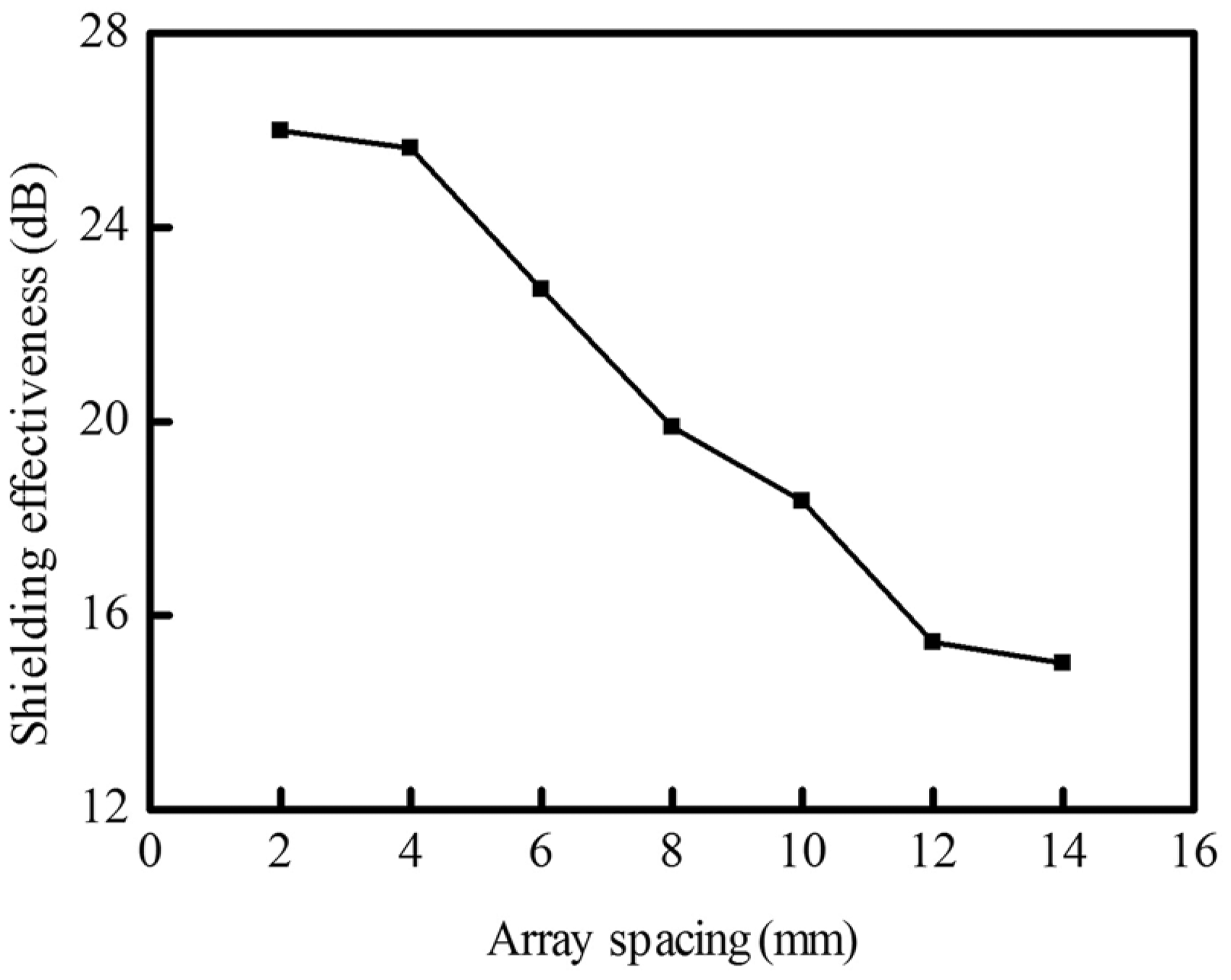
Thomassin et al. [21] have revealed that the higher SE above 35 dB was regarded as effective shielding for general electromagnetic shielding materials. The characterization of shielding performance was also characterized by effective bandwidth, i.e. the frequency bandwidth of the electromagnetic wave when the SE was higher than 35 dB. Figure 4 presented the effects of array spacing on the effective bandwidth in three-layer samples with the same overlap angle 0° of three layers (0°–0°–0°). The effective bandwidth tended to decrease with the higher array spacing. When array spacing was lower than 8 mm or higher than 14 mm, there was a little impact of array spacing on the effective bandwidth. When the array spacing decreased from 14 mm to 8 mm, the effective bandwidth was improved rapidly. It has been speculated that the larger size of the pores in the samples with increasing array spacing was the main factor for this trend shown in Figure 5.
The effects of array spacing on effective bandwidth of three-layer samples with the overlap angle of 0°.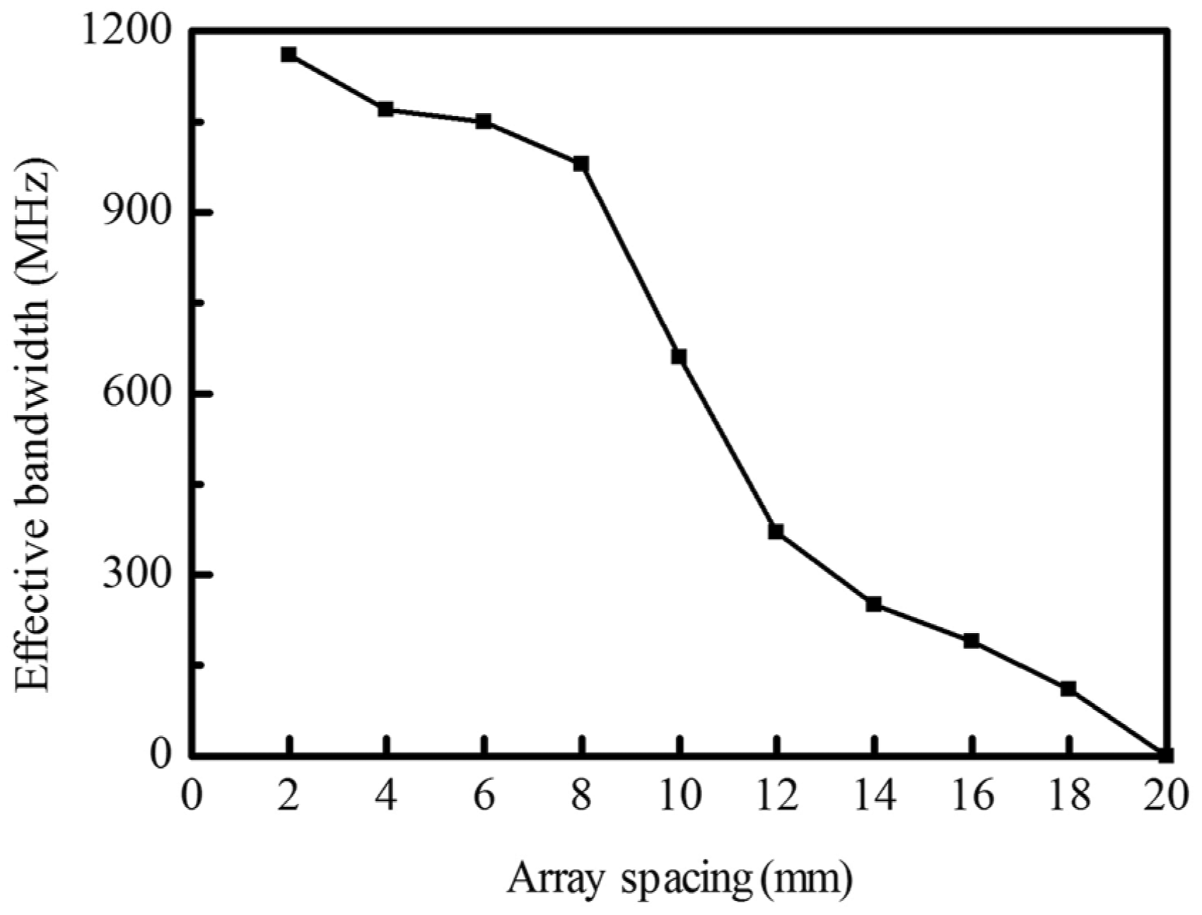
Effect of the number of layers on EMI shielding performance of the polymer-matrix composites
In addition, the number of layers and overlap angle also has an effect on the EMI shielding performance. In order to obtain the maximum SE with the smallest consumption of the CCF, we are thus motivated to study the changes in the EMI shielding performance of the composites and their number of layers and the overlap angle for CCF in greater detail. The shielding performance of the composites over the array spacing of 4 mm, 8 mm, 12 mm, and 16 mm as a function of the frequency of 140 MHz, 390 MHz, 640 MHz, 1000 MHz for the single-, two-, and three-layer samples with the same overlap angle of 0°. The results are shown in Figure 6.
The effects of the number of layers on the SE of composites with different array spacings: (a) 4 mm, (b) 8 mm, (c) 12 mm, and (d) 16 mm.
As shown in Figure 6(a–c), at the low frequency of 140 MHz and 390 MHz, the composites exhibited a relatively enhanced EMI SE with increase of the number of layers, but below the general effective SE of 35 dB. There was a 10 dB decrease of the EMI SE of the two-layer composites with the array spacing of 16 mm in Figure 6(d). The possible reason was that the relatively low EMI frequency could easily transmit the large pores. This result is consistent with the theoretical prediction that thickness is only critical at relatively low frequencies. However, at relative high frequencies, even thin conductive substrates are effective shields. It has been verified in Figure 6.
At the high frequency of 640 MHz and 1000 MHz, Figure 6(a) and (b) all showed rarely no increase of EMI SE of the two-layer composites with relatively compact arrangement of CCF (the array spacing of 4 mm, 8 mm), while the SE of the three-layer samples with the same array spacing was increased little when increasing the number of layer from 2 to 3. The EMI SE of the samples reached in the average range of 40–48 dB when the array spacing was 8 mm and maximum value of 46.8 dB at the frequency of 1000 MHz. Figure 6(c) and (d) presented that only the EMI SE of the three-layer samples was above 35 dB due to the large size of pores, which the high EMI frequency could transmit easily.
Effect of overlap angle on EMI shielding performance of the polymer-matrix composites
The SE of the two- and three-layer composite samples is plotted in Figures 7 and 8 at four specific frequencies of 140 MHz, 390 MHz, 640 MHz, and 1000 MHz, respectively, which represent the full testing frequency band (30 MHz–1.5 GHz). It is aiming to clarify the effects of overlap angle on the EMI shielding performance at different array spacings. The SE of the PET-spunbond woven substrates without CCF is almost null and was not shown here.
The effects of overlap angle on SE of two-layer samples at different frequencies: (a) 140 MHz, (b) 390 MHz, (c) 640 MHz, and (d) 1000 MHz. The effects of overlap angle on SE of three-layer samples with overlap ways of 0°–0°–0°, 45°–0°–0°, 0°–45°–0°, and 0°–0°–45° at different frequencies: (a) 140 MHz, (b) 390 MHz, (c) 640 MHz, and (d) 1000 MHz.
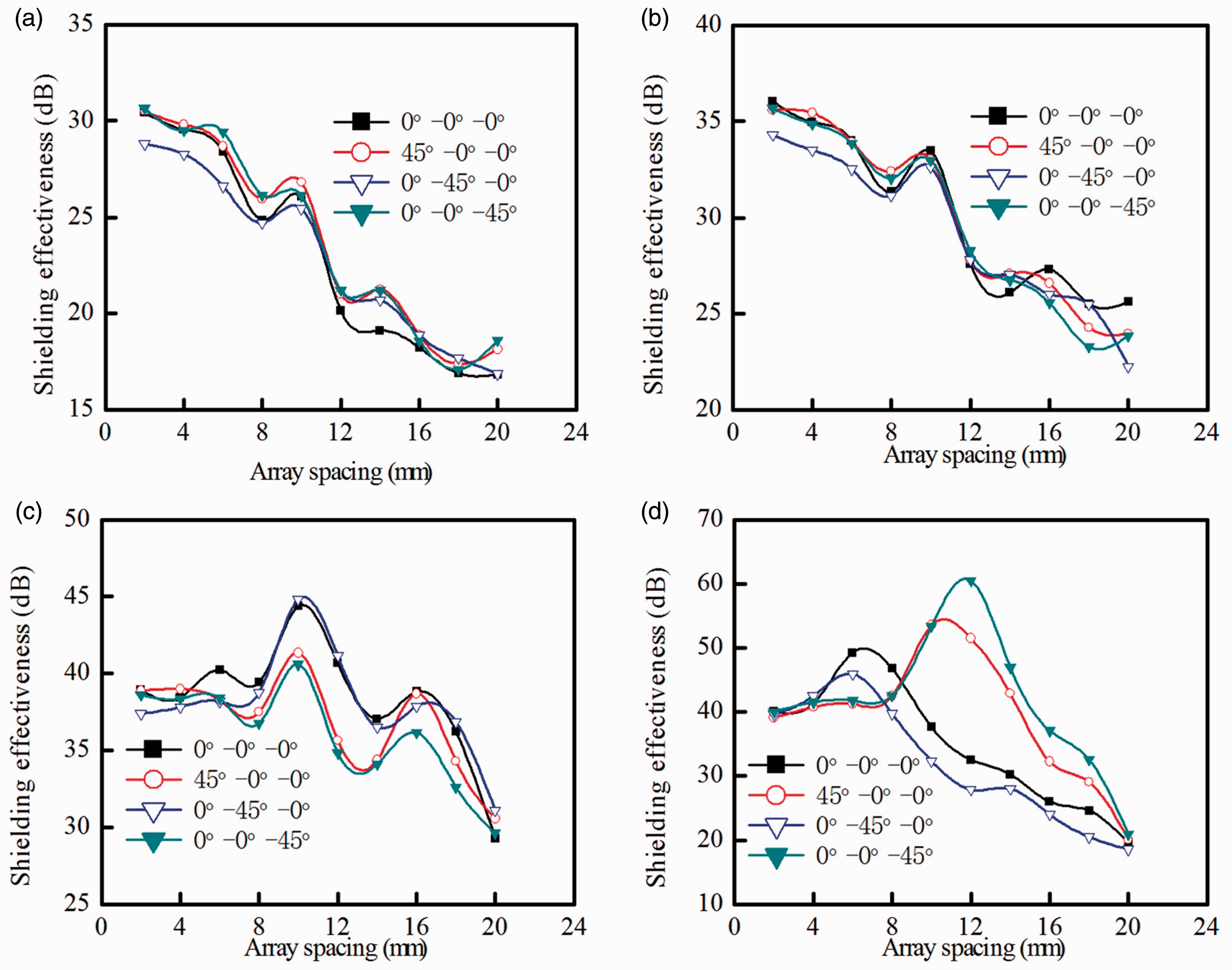
Figure 7 showed that the SE of the two-layer sampled overlapped by 45° was a little higher than that overlapped by 0° at the low frequency of 140 MHz and 390 MHz, and it was opposite at the frequency of 640 MHz. Even so, only the SE of samples in Figure 7(c) and (d) could be above 35 dB. Especially, the maximum SE of sample in Figure 7(d) reached 47.44 dB, overlapped by 45°, with array spacing of 12 mm, and at the relatively high frequency of 1000 MHz, which was almost the same as that with array spacing of 6 mm. This indicated that the overlap angle could affect the shielding performance at relatively high frequency, and that the larger the overlap angle is, the higher the SE will be, at the general frequency. This result also indicates that larger overlap angle can also reduce the consumption of CCF to achieve the same effective shielding performance. This is consistent with the research of Jou [14], and implies that the effect of CCF orientation is more significant than that of CCF content [14].
Figure 8 compared the SE of the three-layer composite samples overlapped by 0° and 45°. There was only one layer rotated, either the first, second, and third layers from top to bottom for an overlap angle of 45°. The difference in SE among different angles for the three-layer samples is not significant in Figure 8(a) and (b) at the relatively low frequency. However, there was a fluctuation at the relatively high frequency of 640 MHz and 1000 MHz in Figure 8(c) and (d). In addition, these samples could present effective shielding performance at the relatively high frequency, with array spacing below 16 mm. And the highest SE of the three-layer samples was 60.49 dB at the frequency of 1000 MHz, with array spacing of 10 mm and the overlap way 0°–0°–45°.
Conclusions
A different structure of the CCF composites with excellent EMI shielding performance was developed in this study. The shielding performance of the CCF composites was determined by the array spacing of CCF, the number of layers, and the overlap angle, and was measured within the frequency band of 30 MHz–1.5 GHz, which includes the major electromagnetic wave frequency from daily electronic device or apparatus. Within the frequency band of 30 MHz–750 MHz, the SE was enhanced with the decrease of the array spacing and the increase of the number of layers mainly due to the increase of the CCF content. Nevertheless, within the frequency band of 750 MHz–1.5 GHz, the number of layers presented little effect on the shielding performance for the reason that the effect of CCF orientation is more significant than that of CCF content. And when the array spacing was 8 mm and the maximum value was 46.8 dB at the frequency of 1000 MHz. For multilayer composites, the shielding performance was improved by the synergistic effects of overlap angle and array spacing. Hence, the composite with three layers, array spacing of 12 mm, and overlap angle of 0°–0°–45° achieved the highest EMI shielding properties of 60.49 dB, corresponding frequency of 1.0 GHz. This study indicated an efficient and economic method to fabricate the EMI shielding composites with less CCF and to achieve superb shielding performance. This will be significant for the EMI shielding composite industry such as the electronic, medical, and military fields.
Footnotes
Declaration of Conflicting Interests
The author(s) declared no potential conflicts of interest with respect to the research, authorship, and/or publication of this article.
Funding
The author(s) disclosed receipt of the following financial support for the research, authorship, and/or publication of this article: This work was made possible by support from Industry-academic Joint Technological Prospective Fund Project of Jiangsu Province (No. BY2013015-24 and No. BY2013015-20); the Open Project Program of Key Laboratory of ECO-Textiles (Jiangnan University), Ministry of Education, China (No. KLET1107); the Opening Project of National Engineering Laboratory for Modern Silk (No. KJS1312); the Jiangsu Provincial Natural Science Foundation of China (No. BK2012112); and National Natural Science Foundation of China under Grant No. 31201134 and No. 31470509.