
Abstract
Electromagnetic shielding (ES) is an important aspect in selecting the material for designing of highly sensitive electronic devices controlled by radio frequency wave due to electromagnetic interference (EMI). Due to intense interaction of high frequency wave with the shielding material, the design of material with suitable impregnation of impurity influences the shielding mechanism. In the present investigation EMI shielding performance and electromagnetic absorption characteristics of epoxy blended graphene impregnated carbon fiber composite (EPCF@1%GN) has been intensively studied. The surface morphology of the sample EPCF@1%GN has been studied through Field emission scanning electron microscopy (FESEM) which provides the morphological facilitation to enhance the shielding effects of the fabricated material. The computation of shielding parameters indicates that the reference composite without graphene demonstrates the lowest total shielding effectiveness. In contrast, composites with graphene content exhibit significantly improved in EMI shielding performance about 20 dB for EPCF@1%GN, with nearly 70% more than for epoxy blended carbon fiber composite (EPCF) which may contributed due to enhanced absorption capability of the material designed. Additionally, the thermal tolerance has been analyzed through Thermo gravimetric analysis (TGA). Composites with graphene content displayed varying porosity characteristics, which may influence their electromagnetic properties highlighting shielding mechanism for microwave absorption. The significance of this study addresses the critical need for effective electromagnetic interference (EMI) shielding materials, particularly for applications in electronic devices, aerospace, and defense sectors. Traditional metal-based shielding materials, while effective, suffer from limitations such as weight and corrosion. This research explores a lightweight, polymer-based composite, offering a high-performance alternative with superior microwave absorption capabilities. The work highlights the transformation of EPCF@1%GN composite from reflection-dominated to absorption-driven shielding behaviour. The excellent thermal stability up to 625°C and enhanced dielectric losses, interfacial polarization, and improved impedance matching make this composite highly suitable for EMI shielding in advanced applications.
Keywords
Introduction
Electromagnetic interference (EMI) is a significant concern in today’s technologically advanced world. The insertion of wide range of electromagnetic sources, radio waves, power lines, and various electronic devices, can disrupt the proper functioning of sensitive electronic equipment. 1 These disruptions can lead to malfunctions, degraded performance, and even complete failure of crucial systems. Thus electromagnetic (EM) shielding plays a crucial role in safeguarding these devices by preventing interference from unwanted electromagnetic signals. This shielding not only ensures the proper functioning of individual devices but also mitigates the risk of cross-interference among multiple systems, which is essential in environments with numerous electronic devices operating simultaneously. 2 In specific applications, such as military and secure communication systems, electromagnetic shielding is vital for preventing eavesdropping and protecting sensitive information from interception. 3 Beyond the functionality and security of electronic equipment, electromagnetic shielding also has significant implications for human health. Prolonged exposure to high levels of EM radiation can have potential health risks, making shielding an important measure for protecting both devices and individuals from the adverse effects of electromagnetic radiation. 4 Traditional materials used for shielding, such as metals like aluminum, copper, and silver, have been widely employed due to their high electrical conductivity, which enables them to reflect and absorb electromagnetic waves effectively. 5 However, these metals can be heavy and prone to corrosion over time. With advancements in material science, lightweight, non-metallic materials like alloys, ceramics, conductive polymers, and metal-coated fabrics have been developed to offer greater flexibility and improved performance. While these materials are versatile, they often suffer from lower conductivity and durability compared to metals. The importance of ongoing research in this field cannot be overstated. Future studies should focus on addressing the limitations of current materials by developing low-density, lightweight, flexible, and highly conductive composites. Improved methods for manufacturing and integrating shielding materials, along with innovations in materials that offer high reflection loss, wide absorption bandwidth, better environmental stability, corrosion resistance, and tunable electromagnetic properties, are critical areas for exploration. Additionally, research into nanomaterial, such as graphene, carbon nanotubes, and other carbon allotropes, holds great promise for advancing electromagnetic shielding technologies. These materials have demonstrated exceptional potential for providing high performance shielding while being lightweight and flexible, making them ideal for modern applications. Carbon fiber is widely utilized in lightweight applications due to its exceptional mechanical strength, low density, and excellent chemical resistance. Its high-temperature stability has attracted significant research interest, particularly as a reinforcing material, as it can be readily incorporated into various configurations. 6 Additionally, the large aspect ratio of carbon fibers enables tunable electrical conductivity. However, their inherently non-magnetic nature limits their attenuation capacity for electromagnetic (EM) waves. This limitation can be addressed by incorporating dielectric or magnetic fillers. Wan et al. synthesized Fe-Co alloy-coated carbon fibers, achieving outstanding electromagnetic shielding performance with a thickness of 1.8 mm. 7 Furthermore, graphene, a two-dimensional allotrope of carbon, possesses a large surface area, enhancing interactions with polymer matrices. 8 However, pristine graphene exhibits poor impedance matching, as reported by multiple studies. Yu et al. demonstrated that pristine graphene has a weak capacity for EM wave absorption. 9 To address this, graphene is often integrated with magnetic materials to enhance its shielding properties. Shen et al. reported that graphene@Fe3O4 composite foams exhibited excellent shielding effectiveness of 41.5 dB in the 8–12 GHz frequency range 10 . Another approach to improving the shielding effectiveness of composite materials is by enhancing their electrical conductivity. This can be achieved by incorporating graphene into carbon fiber composites. Graphene even at low loadings, has been shown to significantly enhance material properties. Its unique combination of micrometer scale dimensions, high aspect ratio, superior electrical conductivity, and two dimensional sheet geometry makes it an effective reinforcement for carbon fiber based composites, contributing to improved EM wave attenuation and shielding performance. Furthermore, the synergistic effect between graphene and carbon fiber plays a crucial role in enhancing the shielding properties of the composite. Graphene acts as an efficient conductive bridge between carbon fibers, facilitating electron transport and promoting multiple internal reflections of electromagnetic waves. This interaction not only improves impedance matching but also enhances shielding performance. The present investigation provide microwave absorption performance of carbon fiber fabric (CFF) reinforced with inclusion of nanoparticle (GNP). Though many works has been performed with either CFF or GNP within the polymer matrix epoxy material, it is observed that shielding efficiency is not up to the Remark.11,12 Qiu et al. reported that graphene agglomeration is a key factor deteriorating the interfacial properties of composites, thereby limiting their electromagnetic interference (EMI) shielding effectiveness 13 which is most emerging issues in development of EMI shielding material in the present scenario. The present challenging issues has been meet by optimizing the wt% of graphene in an accomodable approach systematically. Further, the incorporation of such reinforcing materials in polymer composites not only retains the inherent properties of individual constituents but also shows the characteristics that neither component exhibits independently. 14 The incorporation of fillers enhances the interfacial surface area within the polymer matrix, facilitating stronger interactions. Due to their nanoscale dimensions, they significantly improve the overall properties when embedded in the polymeric matrix. 15 Despite extensive research on EMI shielding using traditional metals and emerging carbon-based materials, several critical gaps remain. While carbon fiber fabric (CFF) and graphene nanoparticle (GNP) composites have been explored individually, their combined effect in a polymer matrix has not achieved optimal shielding efficiency. Existing studies often focus on either high electrical conductivity or lightweight flexibility, but fail to balance both effectively. There is a pressing need to develop next-generation shielding materials that integrate high conductivity, approaching broadband absorption, mechanical robustness, and environmental resilience which can be addressed by systematic experimental work as described in the present context. In the present work, Carbon-based materials, particularly graphene incorporated systems, have demonstrated significant potential as microwave absorbers due to their high electrical conductivity, large surface area, and distinctive electronic properties. These characteristics enable efficient absorption and dissipation of electromagnetic waves, making them highly effective for EMI shielding applications.
Electromagnetic wave analysis for shielding performance
Shielding effectiveness (SE) of a material is largely determined by its composition and different factors like electrical conductivity, magnetic permeability, and permittivity, which influences how the material interacts with electromagnetic waves. The interaction of electromagnetic waves with a shielding material can be explained through reflection, absorption, and transmission as illustrated in Figure 1. When an incident wave strikes the material, a portion is reflected at the surface due to impedance mismatch. The remaining wave penetrates the material, where absorption occurs due to the mechanism such as dipolar polarization, interfacial polarization. These polarization effects enhance energy dissipation by trapping and redirecting the wave inside the shielding structure. Further, Conductive loss occurs due to the movement of charge carriers, leading to Joule heating, while eddy currents generated in conductive materials further attenuate the wave. If the material has magnetic components, resonance phenomena, such as natural and exchange resonance, contribute to energy dissipation by interacting with the wave magnetic field. Multiple reflections within porous or layered structures lead to additional attenuation before the remaining wave is transmitted through the material. The material’s permittivity, especially its imaginary component, contributes to dielectric losses, boosting SE. A dielectric medium is a non-conducting material that can support an electric field, allowing electromagnetic waves to propagate through it. In a dielectric medium, the material’s response to the electric field is characterized by its permittivity ϵ and permeability μ. In the context of Maxwell’s wave equations, a dielectric medium does not have free charges Interaction of shielding material in presence of EM wave.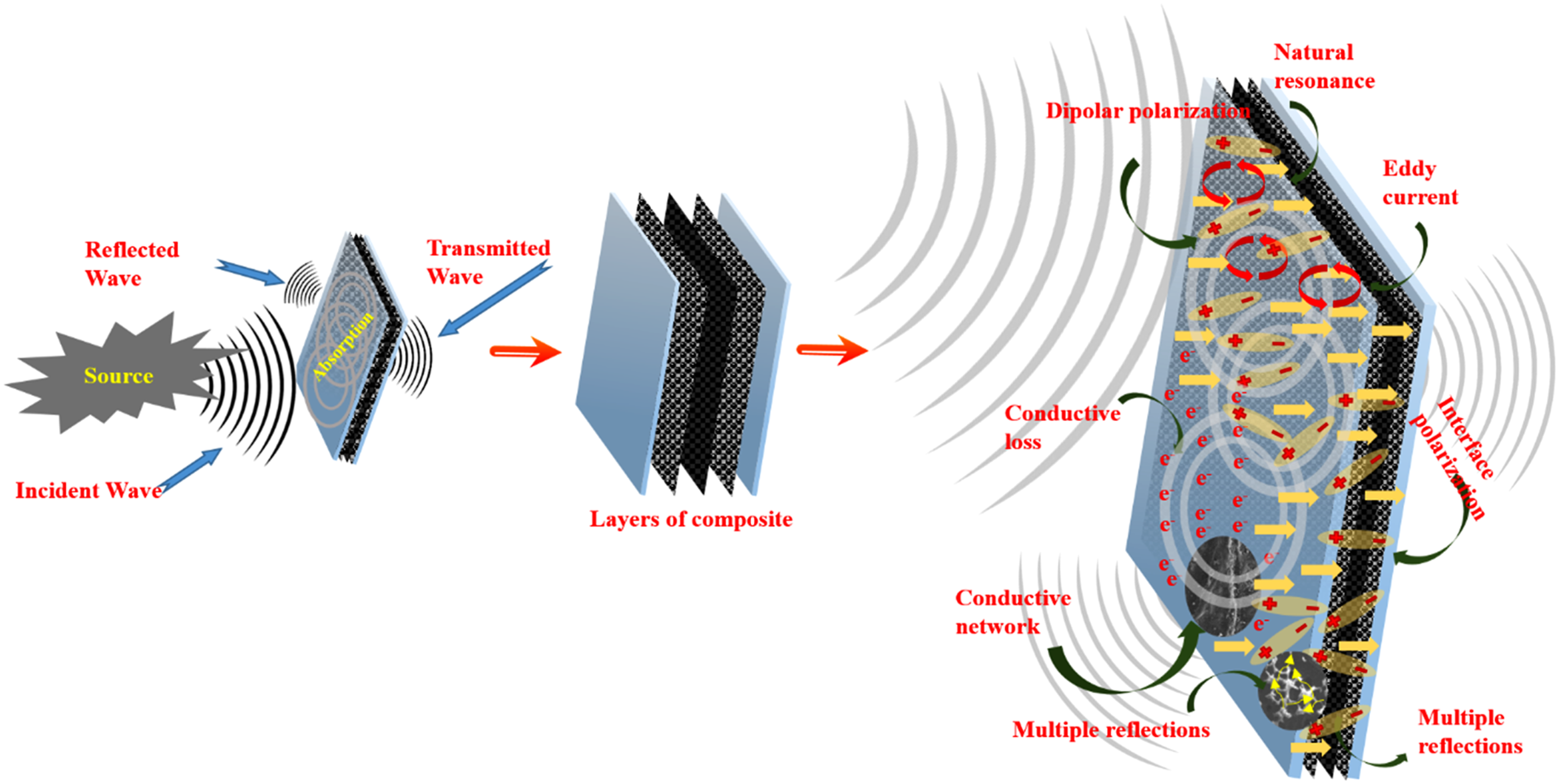

Equation (2) explain the behavior of electromagnetic wave with an initial amplitude
Substituting Equation (2) in (1)

This implies the dispersion relation

Now, considering the incident of an electromagnetic wave on a shielding material it is observed that at the boundary between the dielectric medium and the shielding material as shown in Figure 1, the boundary conditions must satisfy the continuity of the tangential components of the electric and magnetic fields. Let the shielding material have complex permittivity

Equation (5) describes speed and wavelength of the incident wave as it enters the shielding material.
And also explain the influence of complex permittivity and permeability on wave dispersion, impacting the attenuation and phase velocity inside the shielding material. The wave inside the shielding material will attenuate due to the imaginary parts of the permittivity and permeability, leading to an exponential decay in the field:

In Equation (6) the term
Now the shielding effectiveness (SE) which is the logarithmic ratio of the power of the incident wave to the power of the transmitted wave given by


For calculation of shielding effectiveness experimentally the measurement of S-parameter has been performed through two port network analyzer. The experimental setup for shielding parameters measurement is illustrated in Figure 2. Experimental Setup for shielding measurement.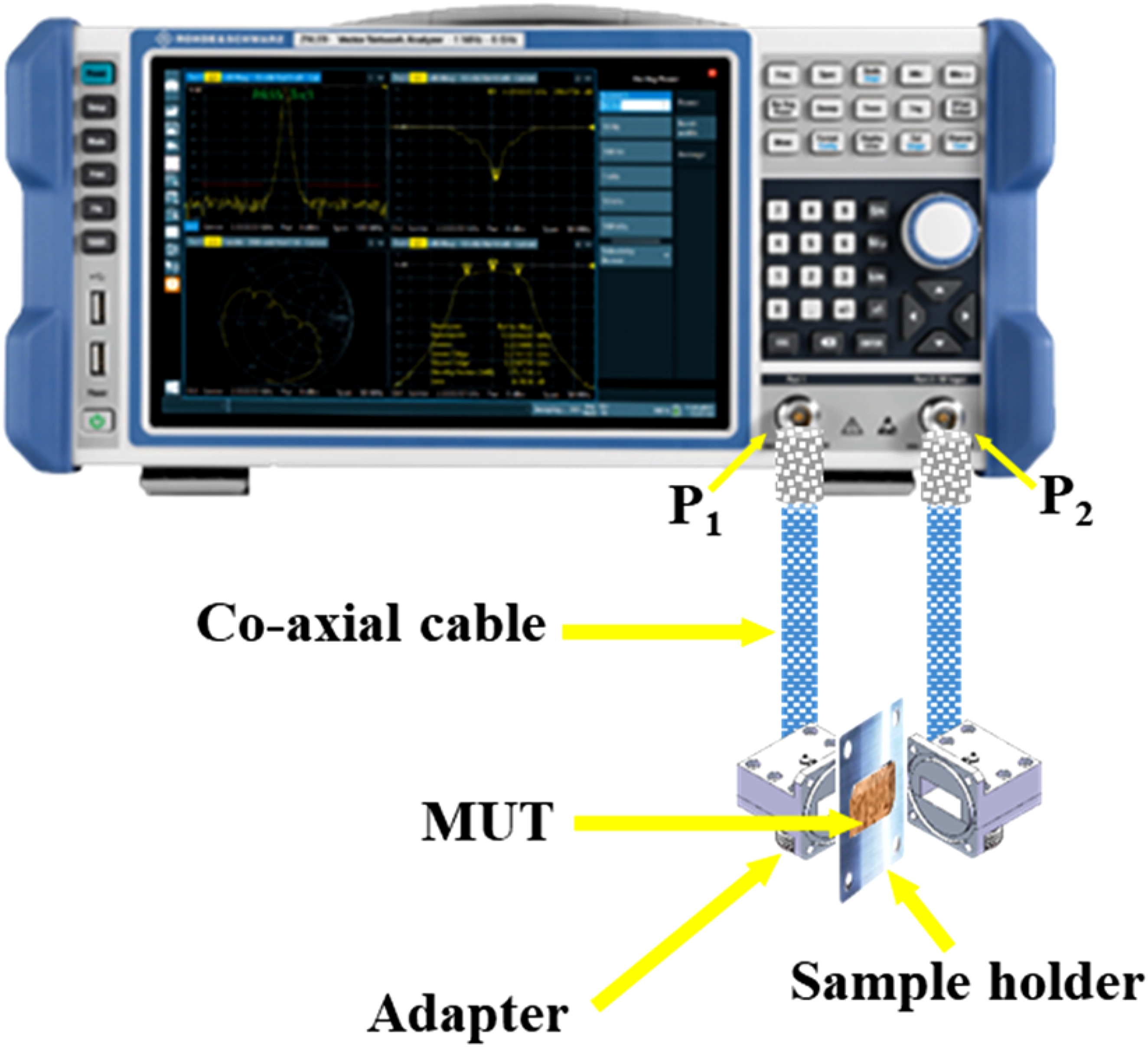
Prior to the measurement, the Vector Network Analyzer (VNA) illustrated in Figure 2 was calibrated using the through-reflect-line (TRL) calibration method, which involves open, short, and matched 50 Ω load standards. This calibration effectively eliminates systematic errors arising from cables, connectors, and measurement uncertainties, ensuring the accuracy of recorded S-parameters (S11, S12, S21 and S22) within the X-band frequency range (8.2–12.4 GHz). During the experiment, the SE was determined based on the measured S-parameters, which provide information on reflection (SER), absorption (SEA), and multiple internal reflections (SEM) of electromagnetic waves interacting with the composite. In two port network analyzer, S11 (S22) represents reflection coefficient (R) and S12 (S21) represents transmission coefficient (T). These coefficients can be mathematically expressed as per Equations (9) and (10).
The absorption loss (SEA) and reflection loss (SER) can be calculated using the following equation,

Equation (11) represents the attenuation of electromagnetic waves within the material due to energy absorption. It accounts for the portion of the incident wave that penetrates the material but does not transmit through it. Further, Equation 12 quantifies the reduction in wave intensity due to reflection at the material interface.
Therefore, Equation (8) for total EMI SE can be rewritten as,


Here, SEM in Equation 13, was ignored because it primarily occurs at interfaces or surfaces within the material. In this study, the multiple reflection loss (SEM) is not considered in the total shielding effectiveness (SET) because it cannot be measured separately in the experimental setup. The total EMI SE is typically described as the sum of three factors: reflection loss (SER), absorption loss (SEA), and multiple reflection loss (SEM). However, in this case, SEM was ignored because SEM primarily occurs at interfaces or surfaces within the material. It is generally accepted that when the absorption loss (SEA) is greater than 10 dB, most of the re-reflected waves are absorbed by the material. In such cases, multiple reflections can be considered as part of the absorption loss. Since SEA was likely high in the measured samples, the multiple reflections were effectively absorbed by the material, and SEM became negligible in the overall result. Further, the experimental setup using the Vector Network Analyzer (VNA) measures reflection and transmission (S-parameters) directly. While the VNA provides data for reflection loss (SER) and absorption loss (SEA), it does not separately account for the multiple reflection losses within the material. Therefore, SEM was not included in the total SE calculation, as it was not captured by the measurement setup.16–18 By combining the logarithmic terms, Equation 15 shows that the total shielding effectiveness is directly related to the inverse of the transmission coefficient (T) which highlights that the lower the transmitted power, higher will be the shielding effectiveness.
Characterization and experimental measurement
Material used in fabrication
The carbon fiber fabrics (CFF) used in this study were commercially procured from Carbon Black Composites, Maharashtra, India. Analytical-grade nitric acid (HNO3,70%) was sourced from Central Drug House (P) Ltd. The sizing agent, 3-glycidyloxypropyltrimethoxysilane (purity >97.0%), was obtained from Tokyo Chemical Industry (India) Pvt. Ltd. Graphene Platelet Nanopowder (GNP) with an approximate carbon content of 99.5% and a bulk density of 0.10 g/mL were procured from Sisco Research Laboratories Pvt. Ltd. The bi-functional epoxy resin LY556, along with HY951, an aliphatic primary amine hardener, both supplied by Herenba Instrument and Engineers. Pidilite silicon spray, acquired from WD-40 Company Ltd, was employed as a release agent to facilitate easy demolding of the prepared composite.
Fabrication of shielding material
The shielding material was fabricated using a three-step process, resulting in a composite with a total thickness of 3 mm, comprising carbon fiber fabric (CFF) impregnated with graphene nanoparticle (GNP) blended epoxy polymer as illustrated in Figure 3. In Step 1, surface treatment of the carbon fiber fabric has been performed to enhance interfacial adhesion and compatibility with the epoxy matrix. The CFF was immersed in nitric acid at ambient temperature for 2 hours to introduce functional groups on its surface, improving wettability. Subsequently, the treated CFF was subjected to a resizing process by immersing it in a sizing agent for 10 minutes, followed by drying at 60°C for 2 hours. In Step 2, the preparation of the epoxy resin and GNP solution began with allowing the epoxy resin to settle in a beaker for 3-4 hours to minimize the presence of trapped air bubbles. Subsequently, the required amount that is 1 wt% of GNP was incorporated into the epoxy resin, and the mixture was subjected to magnetic stirring in a controlled direction at room temperature to prevent air entrapment and promote uniform dispersion. The stirring process was continued until a homogeneous dispersion of GNP within the epoxy matrix was achieved. Following this, a hardener was introduced into the mixture at a predetermined weight ratio of 10:1. The resulting solution was further stirred for a few additional minutes to ensure complete mixing and uniform distribution of the hardener throughout the matrix, leading to the formation of a well dispersed epoxy GNP solution. In Step 3, the prepared resin mixture was poured into a mold lined with a 0.5 mm thick Teflon sheet pre-treated with a silicone based release agent to facilitate smooth demolding. The resized carbon fiber fabric was manually placed onto the resin using the hand layup technique. The remaining resin was uniformly spread over the fabric using a hand roller to ensure thorough impregnation. The mold was left to cure at ambient temperature for 12 hours, resulting in the final composite structure. The selection of 1 wt% graphene nanoparticle (GNP) content in EPCF@1%GN composite was based on a systematic approach considering its impact on electromagnetic interference (EMI) shielding performance, electrical conductivity, and structural integrity. The incorporation of GNPs enhances the dielectric properties of the composite, primarily through polarization mechanisms. However, excessive GNP content may lead to conductivity saturation and increased reflection rather than absorption. Through preliminary trials, it was observed that 1 wt% GNP loading provides balance between impedance matching and dielectric loss, ensuring significant energy dissipation while minimizing reflection losses. Further A higher GNP content could have increased conductivity excessively, leading to impedance mismatch and higher reflection rather than improved absorption. Moreover, it is difficult to control the agglomeration with higher concentrations of GNPs loading which may lead to uneven dispersion within the epoxy matrix. This could result in weak interfacial bonding, affecting mechanical properties and processing challenges during composite fabrication. With significantly less loading such as 1 wt% GNP composition ensures uniform dispersion without significant agglomeration thereby maintaining structural integrity and effective load transfer between matrix and reinforcement. Steps followed for fabrication of shielding material.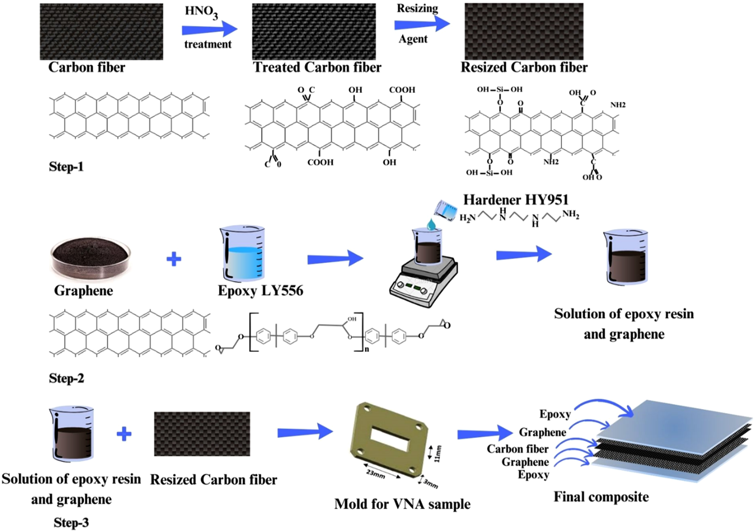
Characterization
The microwave absorption properties of the composite, along with its other critical characteristics, were systematically characterized using advanced analytical techniques to obtain detailed insights into its material performance. Field Emission Scanning Electron Microscopy (FESEM) was performed using the JEOL JSM-IT 800 (Tokyo, Japan) to examine the detailed surface morphology, highlighting the significance of the fiber-matrix interface and interfacial adhesion. The thermal stability of the composite was assessed through Thermo Gravimetric Analysis using TGA Analyzer (Shimadzu Corporation, Japan), offering critical data on its thermal degradation. The S-parameters assessed for shielding behavior analysis in the X-band frequency range were determined using a Rohde & Schwarz ZNLE14 Vector Network Analyzer calibrated with a WR-90 waveguide kit.
Results and discussion
Surface morphology analysis of EMI shielding material
The shielding effectiveness of any electromagnetic interference (EMI) shielding material is critically influenced by its surface structure and composition, where electromagnetic (EM) waves interact at the atomic level to dictate the material’s shielding efficiency. FESEM analysis of the epoxy polymer carbon fiber@1% GNP (EPCF@1%GN) composite illustrated in Figure 4 shows that the carbon fibers are completely enveloped by the epoxy matrix, signifying strong interfacial bonding. This complete encapsulation of the fibers within the matrix is crucial for effective load transfer, which not only enhances the mechanical integrity but also contributes to improved EMI shielding performance through reduced interfacial defects that could otherwise allow EM wave leakage. Furthermore, the FESEM images highlight the presence of graphene nanoparticle (GNP) agglomerates distributed near the fiber-matrix interface as shown in Figure 4(a). These agglomerates are pivotal for boosting the shielding performance as they create conductive pathways and interconnected networks within the composite. FESEM image of EPCF @1% GN composite (a) ×2000 magnification (b) ×1000 magnification.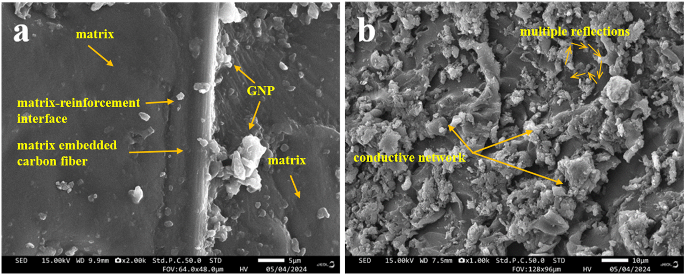
The distribution and alignment of GNPs in proximity to the fibers suggest that the material structure promotes multiple reflection and absorption mechanisms, contributing to high shielding efficiency. The fibrous network, coupled with uniformly dispersed GNPs, facilitates enhanced dissipation and attenuation of EM waves, thereby increasing the material’s overall shielding effectiveness. Figure 4(b) presents the rough and irregular surface morphology of the EPCF@1%GN composite, which plays a significant role in enhancing its electromagnetic shielding performance. The FESEM images reveal the embedded appearance of carbon fibers within the polymer matrix, along with the distribution of graphene on its surface. With the addition of 1% graphene nanoplatelets (GNP), significant changes in the microstructure, distribution, and topology of graphene sheets are observed. The EPCF@1%GN composite exhibits a rough and irregular surface morphology, which provides additional scattering sites for microwaves, thereby enhancing electromagnetic wave absorption and reflection. The incorporation of GNPs leads to the formation of agglomerates near the fiber-matrix interface, potentially creating interconnected conductive networks that improve electrical conductivity and EMI shielding performance. The increased surface roughness facilitates multiple scattering, extending the path length of incident EM waves within the material, which enhances wave attenuation and dissipation. The presence of GNPs strengthens the interfacial bonding between carbon fibers and the matrix, reducing defects that could otherwise allow EM wave leakage. The improved interfacial adhesion also contributes to enhanced mechanical properties, such as tensile strength and fracture resistance, making the composite more robust. Furthermore, the increased conductive pathways enable better charge carrier mobility, reducing impedance mismatch and further optimizing shielding effectiveness. Consequently, this surface morphology not only augments the absorption capability but also reduces the chances of wave transmission, leading to an overall improvement in the shielding effectiveness of the composite material.
Thermal behavior stability analysis of CFF and EPCF@1%GN composite
Figure 5(a) indicates significant stable thermal behavior of CFF which does not go under any substantial decomposition up to 622°C with remaining residue of 7.317 mg. This slight weight loss of 4.24% could be due to the loss of absorbed moisture or surface impurities, present on the fiber surface. Beyond 622°C, the TGA curve shows a rapid weight loss, which continues up to 1025.86°C until complete degradation is observed which could be due to the breakdown of carbon-carbon bonds within the fiber structure leading to decomposition of the carbon fibers themselves at high temperature leaving residue of 0.004 mg. The TGA curve of the EPCF composite, illustrated in Figure 5(b), exhibits a thermal degradation trend similar to that of the EPCF@1%GN composite in its initial stages, highlighting comparable thermal behavior up to 340°C. The initial weight loss of 5.87% up to 284°C can be attributed to the loss of absorbed moisture, volatile organic compounds, or low molecular weight components present in the epoxy matrix. This trend closely aligns with the EPCF@1%GN composite, where an initial weight loss of 4.69% was observed up to 278.84°C, suggesting that graphene incorporation has a negligible effect on the early thermal decomposition phase. Between 284°C and 340°C, the EPCF composite undergoes rapid weight degradation of approximately 33%, which is consistent with the decomposition of the epoxy resin. This behavior mirrors the thermal degradation phase of EPCF@1%GN in the temperature range of 278.84°C to 358.29°C, where a weight loss of 36.28% was observed. However, beyond 340°C, the degradation pattern of the EPCF composite differs significantly from that of pure carbon fiber fabric (CFF). After the major degradation of the epoxy phase, the EPCF composite exhibits a sudden weight loss of 9.28% (0.174 mg) at around 340°C, followed by an extensive degradation phase extending up to 590°C, where approximately 93% of the remaining residue of the composite decomposes. This behavior differs from that of pure CFF, where degradation continues steadily up to 1025.86°C. The earlier completion of degradation in the EPCF composite suggests that the presence of the epoxy matrix accelerates the breakdown of carbon fibers compared to pure CFF. This discrepancy can be attributed to the interaction between carbon fibers and the degraded epoxy residue. The degradation of the epoxy matrix at lower temperatures produces free radicals and volatile compounds that may catalyze the degradation of carbon fibers. Additionally, the residual epoxy fragments could act as localized thermal hotspots, intensifying the breakdown of carbon fibers within the composite and facilitating their degradation at a lower temperature. The presence of graphene in EPCF@1%GN slightly alters this trend by providing additional thermal stability, delaying complete breakdown until 625.49°C. The TGA curve illustrated in Figure 5(c) reveals a high decomposition temperature, indicating strong thermal resistance and structural integrity of the composite at elevated temperatures. Thermal degradation behavior of carbon fiber fabric and EPCF@1%GN composite highlights the composite’s thermal stability, critical degradation phases, and the influence of graphene and carbon fibers on overall thermal performance of EPCF@1%GN composite in the temperature range of 0°C–1000°C. (a) TGA plot for Carbon fiber fabric. (b) TGA plot for EPCF composite. (c) TGA plot for EPCF@1%GN composite.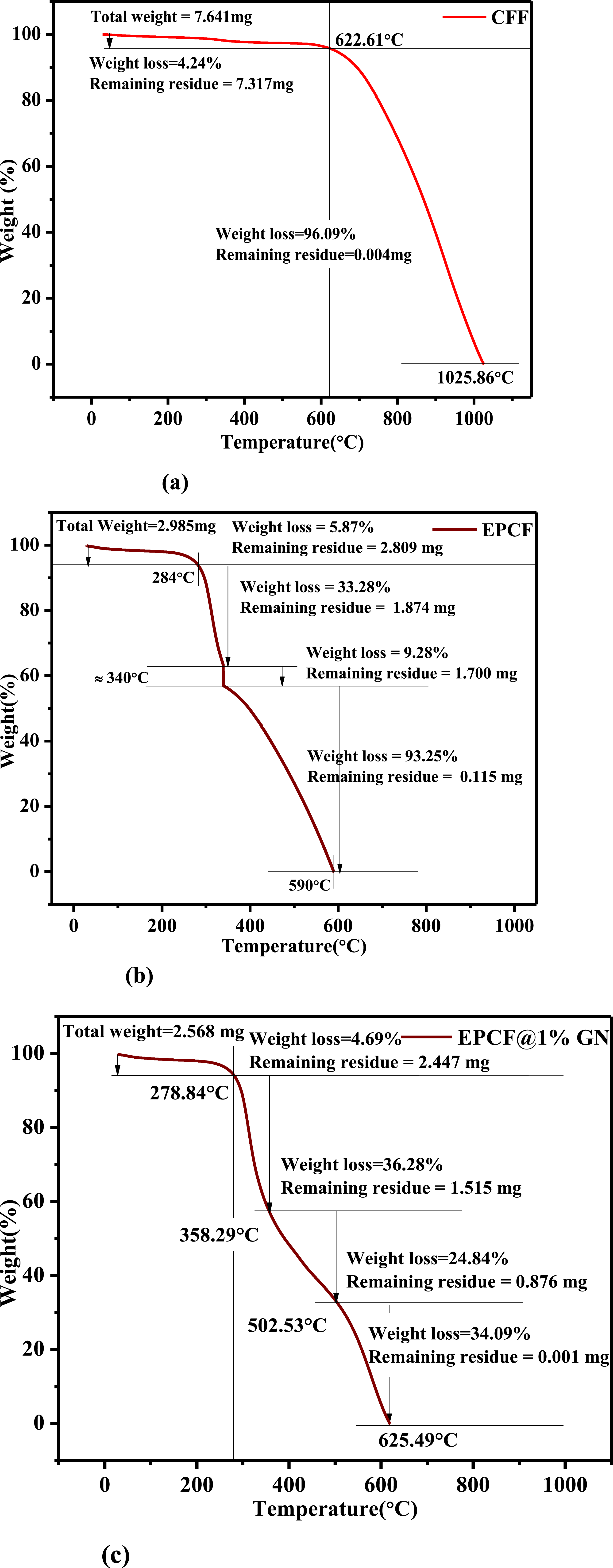
Further the EPCF@1%GN composite shows slow degradation up to 278.84°C with a weight loss of only 4.69%. From 278.84°C to 358.29°C, the composite undergoes rapid degradation, with a weight loss of 36.28% likely corresponds to the decomposition of the epoxy resin. The rapid degradation suggests the thermal decomposition of the polymeric chains within the epoxy resin. 19 Between 358.29°C and 502.53°C, the degradation rate slows down compared to the previous phase, with 24.84% weight loss leaving residue 0.876 mg. This stability phase may indicate the partial degradation of the carbon fibers and the remaining epoxy matrix suggests that graphene and carbon fibers contribute to slowing down the degradation, providing some stability. Beyond 502.53°C, the composite undergoes another phase of rapid degradation until 625.49°C, leaving 0.001 mg residue corresponds to final breakdown of the carbon fibers and any remaining epoxy or graphene. The carbon-carbon bonds in the fibers and graphene degrade completely, leading to total weight loss. The presence of graphene nanoparticles (GNPs) contributes to the stability by acting as a barrier, restricting the movement of polymer chains and delaying thermal degradation which ensures that the shielding properties of the composite are maintained even under extreme conditions, preventing thermal breakdown which lead to negotiated shielding effectiveness and structural deterioration. Thus, the thermal robustness of EPCF@1%GN, as confirmed by TGA, reinforces its suitability for advanced EMI shielding applications.
Microwave measurement and Shielding Performance of EPCF@1%GN composite
Electromagnetic interference (EMI) shielding of materials is primarily defined by their ability to reflect and/or absorb electromagnetic radiation, thereby serving as a barrier to prevent the penetration of EM waves through the shielding medium. This mechanism of suppression helps to ensure that electromagnetic waves not able to interfere with functionality of sensitive electronic devices. For ideal EMI shielding materials, the material’s permittivity and permeability plays the crucial role in matching the impedance and dictate the ability of the composite to achieve effective shielding. Dielectric loss in the material is primarily caused by conductivity and polarization losses which is responsible for electrical shielding and attenuation of wave propagation. The free electron theory of the material suggests that materials with higher electrical conductivity exhibit increased dielectric losses, which enhances their ability to dissipate electromagnetic energy. Ionic and electronic polarization losses, which become prominent at very high frequencies (above 1000 GHz), can typically be neglected in the low microwave frequency range relevant for most EMI shielding applications. Conversely, dipole polarization, which is influenced by the presence of residual groups and structural defects, plays a significant role at lower frequencies and is highly dependent on fabrication parameters, such as material composition and annealing conditions. Additionally, interfacial polarization, arising from trapped space charges at phase boundaries, leads to relaxation effects that further contribute to the overall shielding efficiency of the composite. Thus, understanding and optimizing these dielectric properties is essential for designing effective EMI shielding materials. In evaluating the ability of a material to attenuate EM radiation shielding effectiveness is a crucial parameter. A higher SE value, measured in decibels (dB), indicates a greater reduction in transmitted energy through the material, signifying superior shielding performance. The total shielding effectiveness of a material is the combined effect of three primary mechanisms: reflection, absorption, and multiple internal reflections. Reflection occurs at the material’s surface due to impedance mismatch between the incident EM waves and the shielding material, causing a significant portion of the radiation to be deflected. Absorption involves the dissipation of EM energy within the material. Multiple internal reflections refer to the repeated scattering and absorption of EM waves within the material’s internal structure, further enhancing attenuation.
20
In Figure 6(a) SER shows moderate shielding effectiveness across the frequency range, indicating that reflection has significant contribution to the overall shielding. Further for EPCF@1%GN, the SER is lower than EPCF, which indicates that EPCF is more reflective and addition of graphene into the composite improved impedance matching and reduced the reflection loss as shown in Figure 6(b). For both EPCF and EPCF@1%GN composites, the shielding effectiveness due to absorption (SEA) increases with frequency, indicating enhanced absorption at higher frequencies. The significant improvement in SEA for the EPCF@1%GN composite compared to EPCF highlights the role of graphene in enhancing the material’s capacity to attenuate electromagnetic (EM) waves, making it more suitable for applications requiring high absorption and effective interference mitigation. Reflection loss (SER), absorption loss (SEA) and total EMI shielding effectiveness (SET) of (a) EPCF composite (b) EPCF@1%GN composite.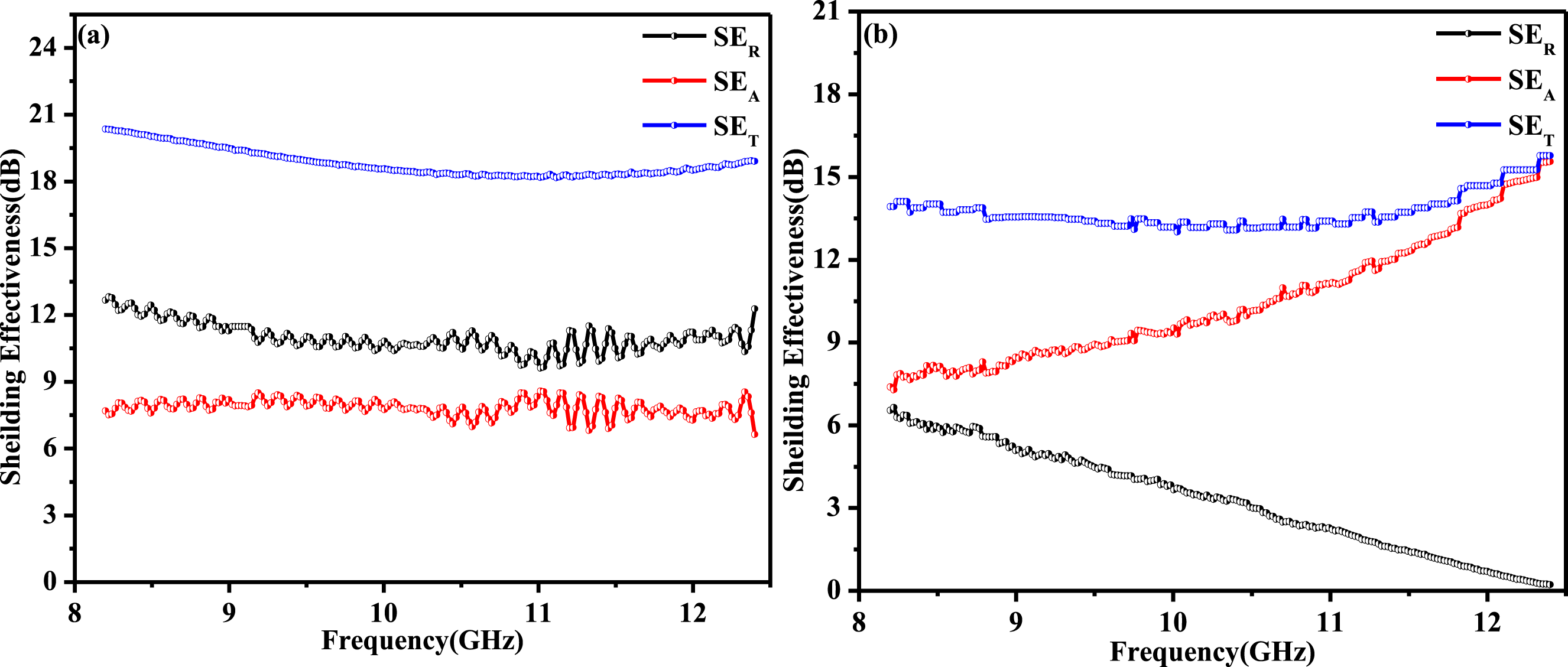
From the FESEM of the material shown in Figure 4(a), and (b), it is clear that at the boundary of GNP-epoxy and GNP-fiber the interfacial polarization along with the dipole polarization due to residual functional groups on the GNPs are created when the EM wave penetrate through it. This leads to energy dissipation as heat, contributing to enhanced absorption. The network formed by the GNPs and carbon fibers promotes multiple scattering and longer wave propagation paths, thereby elevating the overall absorption. The variation in total shielding effectiveness (SE) of the EPCF@1%GN composite with frequency is primarily due to the frequency dependent interactions of electromagnetic waves with the composite’s constituents, such as carbon fibers and graphene nanoparticles (GNPs). At lower frequencies, the SE is mainly governed by reflection, which is influenced by the surface conductivity and impedance mismatch between the material and incident EM waves. When an electromagnetic wave impinges on the composite, free electrons in these components are able to move easily and oscillate in response to the alternating electric field of the EM wave. This movement of free electrons leads to the generation of secondary electric fields that oppose the incident field, causing the wave to be reflected. 21 The impedance mismatch between the composite surface and the surrounding air further enhances reflection due to the limited penetration of the incident wave. As frequency increases, the skin depth decreases, resulting in enhanced wave penetration and higher absorption due to increased dielectric and conduction losses within the composite. 22 This results in a shift from reflection dominated shielding to absorption dominated shielding due to increased dielectric and conduction losses within the composite matrix. The presence of GNPs introduces additional electronic interactions that contribute to energy dissipation. The GNPs, which have a high surface area and conductive properties, create a network of localized charge carriers. Under the influence of an EM field, these charges experience polarization, leading to interfacial polarization at the GNP-epoxy and GNP-carbon fiber boundaries. 23 As electrons move and temporarily trapped at these interfaces, energy from the EM wave is converted into heat, resulting in dielectric and conduction losses. The defects and functional groups on the GNP surface lead to dipole polarization, further enhancing the energy dissipation process. 24 The presence of GNPs facilitates interfacial polarization and conductive network formation, which contribute to higher dielectric loss and absorption at higher frequencies. Furthermore, dipole relaxation and multiple scattering within the composite matrix lead to varying levels of attenuation depending on the frequency which contribute to the observed frequency dependent shielding effectiveness. This interplay between reflection and absorption mechanisms results in a nonlinear variation of SE with frequency across the microwave spectrum. 25 EPCF shows higher SET across the frequency range, indicating consistent overall shielding performance. For EPCF@1%GN the SET is lower than EPCF, indicating that although absorption is enhanced, the overall effectiveness is slightly less due to the lower SER. The addition of graphene significantly increases SEA, indicates that the composite can absorb more EM energy, decreasing transmission through the material. Although the absorption has improved, the overall shielding effectiveness is slightly decreases due to the smaller amount contribution from reflection. The incorporation of 1 wt% graphene into EPCF@1%GN significantly enhances the composite’s ability making it more suitable for applications where absorption is the primary concern.
The decrease in SER suggests that the incorporation of GNP enhances impedance matching, which diminishes reflection.
26
The total shielding (SET) of the EPCF composite varies from 20.34 to 18.64 dB with frequency 8.2 GHz to 10.5 GHz and further increases to 18.89 dB at 12.4 GHz. The slow decrease of SET may be attributed to its intrinsic electrical conductivity and the dominant reflection based shielding mechanism. The carbon fibers in the composite form a continuous conductive network, enhancing surface conductivity and creating a high impedance mismatch with incident electromagnetic (EM) waves. This leads to strong reflection, which primarily governs the overall SET in the material. Furthermore, the conductive carbon network limits the penetration of EM waves, resulting in low transmittance. As a result, the shielding effectiveness remains stable and effective, minimizing wave transmission and maintaining consistent performance throughout the frequency range. The SET of the EPCF@1%GN composite is slightly lower than that of the EPCF. The shielding effectiveness varies from 13.92 to 13.14 dB with increase of frequency from 8.2GHZ-10.5 GHz and further increases to 15.76 dB at high frequency 12.4 GHz. The incorporation of graphene nanoparticles introduces interfacial polarization and dipole relaxation losses, thereby increasing dielectric dissipation and contributing to higher absorption of incident electromagnetic waves. This modification improves impedance matching between the composite and the surrounding medium, minimizing the impedance mismatch that typically leads to high reflection. As a result, the absorption efficiency (SEA) increases and the reflection component (SER) diminishes, leading to a marginally lower overall SET. The absorbance, reflectance and transmittance of the material EPCF and EPCF@1%GN are computed from S-parameter is represented in Figure 7(a)-(c). It is observed that the absorbance of the EPCF is shows a variation from 0.044 to 0.047 with increase of frequency from 8.2GHz to 12.4 GHz and for EPCF@1%GNcomposite it shows a sharp increase from 0.18 to 0.92 with frequency as shown in Figure 7(a). The significant increase is primarily due to the unique conductive and dielectric properties introduced by the addition of graphene nanoparticles (GNPs). GNPs enhances the composite’s ability to dissipate EM energy through multiple mechanisms such as interfacial polarization, conductive network formation, and dipole relaxation.
27
As frequency increases, the electrical conductivity and dielectric constant of the graphene-filled composite also increase, promoting greater dielectric and conduction losses, which facilitate more effective conversion of EM energy into heat.
28
However, the EPCF composite without graphene lacks these additional loss mechanisms and exhibits minimal change in absorbance, as it primarily relies on reflection rather than absorption for shielding. The reflectance is relatively high with an average value of 0.919, for EPCF composite whereas it decreases gradually from 0.778 to 0.048 with increase of frequency from 8.2GHz to 12.4 GHz as shown in Figure 7(b). Similarly transmittance of EPCF composite is very low which is varies from 0.009 to 0.012 and that for EPCF@1%GNcomposite it is 0.040 – 0.026 with increase of frequency as shown in Figure 7(c). The EPCF composite exhibits low absorbance, high reflectance, and low transmittance compared to the EPCF@1%GN composite due to its high surface conductivity and minimal impedance matching with incident electromagnetic (EM) waves. The carbon fibers within the EPCF create a continuous conductive network, which results in high reflection (SER) and low wave penetration, thereby limiting the absorption (SEA) of EM energy. This behavior is governed by the impedance mismatch Z between the material and the free space, where (a) Absorbance (b) Reflectance and (c) Transmittance in case of EPCF and EPCF@1%GN composite.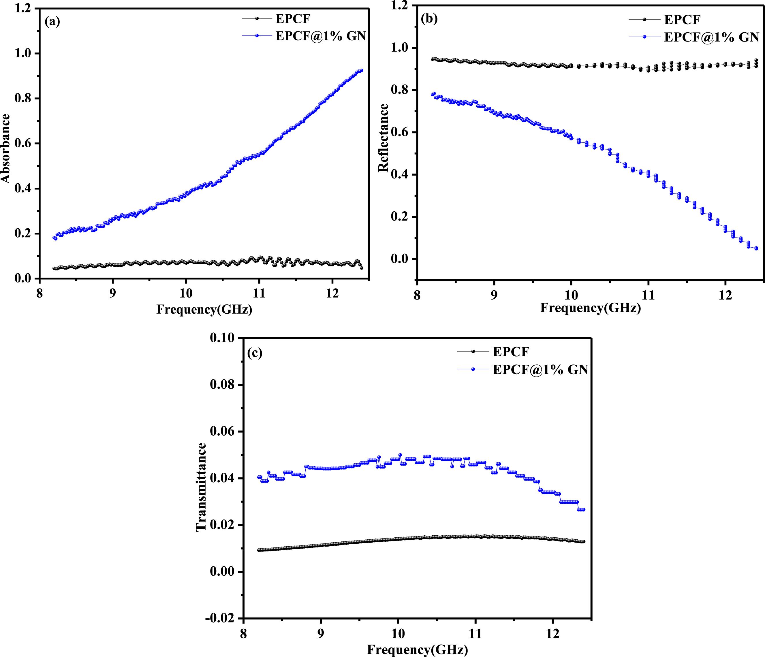
The reflected, absorbed and transmitted power of EPCF and EPCF@1%GN composites exhibit distinct behaviors with frequency due to differences in their electromagnetic (EM) wave interaction mechanisms. For EPCF, the reflected power percentage (R) is significantly high across the frequency range as shown in Figure 8(a) computed from the relation R = ∣S11∣2, where S11 is the reflection coefficient. This may be attributed due to a strong impedance mismatch between the composite and free space, which causes most of the incident power to be reflected. This results in low absorbed power (A) and minimal transmission (T), governed by the relations A = 1−R−T and T = ∣S21∣2, where S21 is the transmission coefficient. In case of EPCF@1%GN composite the reflected component of power shows a higher absorbed power with increasing frequency due to enhanced dielectric and conduction losses induced by GNPs as shown in Figure 8(b). The incorporation of 1 wt% GNPs improves impedance matching, reduces the reflection coefficient (R) and increases the energy dissipation via interfacial polarization and conductive network formation. As a result, the absorbed power percentage rises significantly, particularly at higher frequencies followed by the relation A = 1−R−T, where A shows a positive correlation with frequency, indicating improved microwave absorption. The transmitted power (T) remains low for both composites, but EPCF@1%GN executes reduced reflection and higher absorption due to better impedance matching and dielectric loss mechanisms. Power reflected, absorbed and transmitted percentage in case of (a) EPCF (b) EPCF@1%GN composite.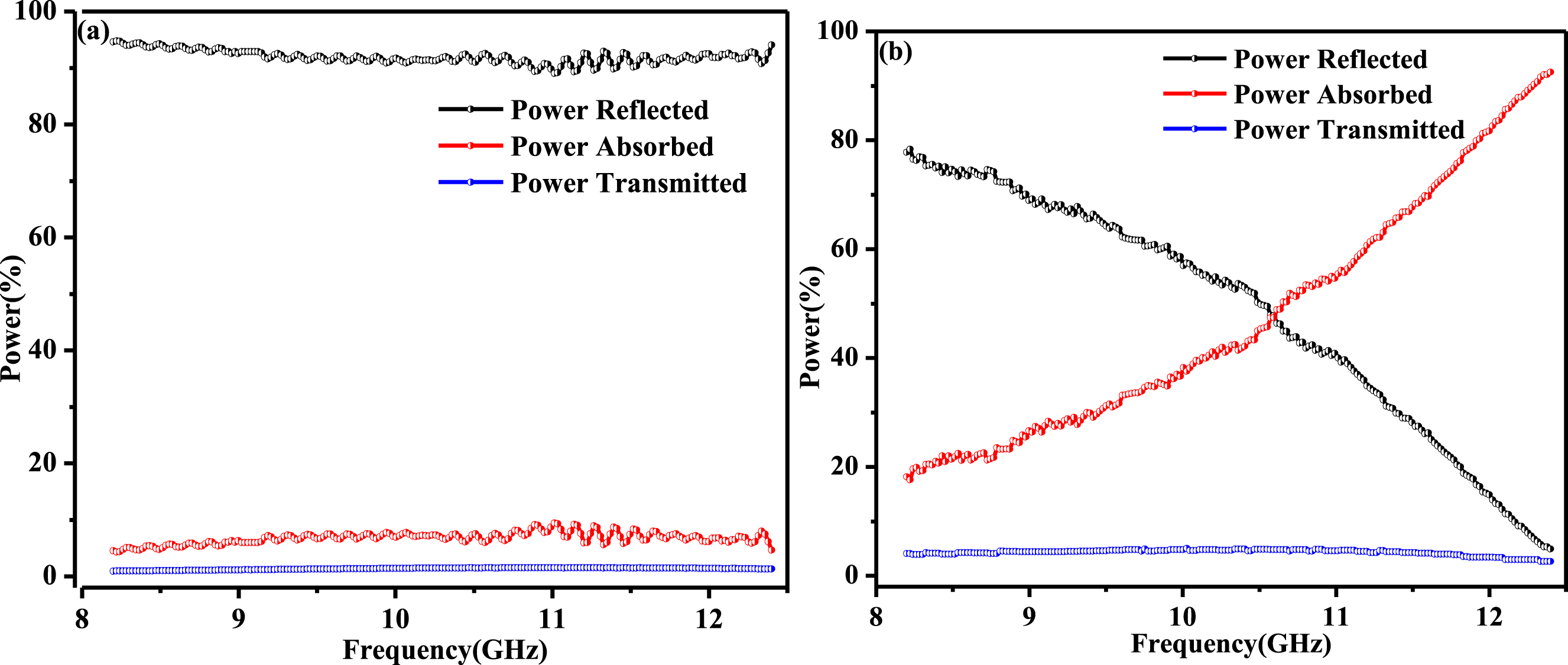
Conclusion
The electromagnetic composites of EPCF and EPCF@1%GN were fabricated using a combination of carbon fiber fabric and epoxy resin, with the latter incorporating 1 wt% of graphene nanoparticles (GN) to enhance electromagnetic interference (EMI) shielding properties. Comprehensive characterization through FESEM and FTIR revealed distinct variations in shielding mechanisms between EPCF and EPCF@1%GN. The shielding effectiveness due to absorption (SEA) and reflection (SER) exhibited distinct behaviors with frequency variations, highlighting the influence of material composition on EMI shielding mechanisms. The EPCF composite demonstrated reflection dominated shielding primarily due to the impedance mismatch at composite air interface. Conversely, the incorporation of 1 wt% graphene significantly improved impedance matching, leading to reduced reflection and enhanced absorption. Further, for EPCF the reflected power remained dominant across the frequency range, with minimal absorption and low transmission. In contrast, EPCF@1%GN exhibited a significant increase in power absorption, with values rising from 0.18 to 0.92 across the frequency range. The transmitted power remained consistently low for both composites, indicating effective shielding properties. The EPCF composite exhibited minimal transmittance, varying from 0.009 to 0.012, whereas EPCF@1%GN showed slightly higher but stable transmission values between 0.040 and 0.026. The reduced reflection coefficient (SER) and increased absorption coefficient (SEA) in EPCF@1%GN demonstrated that graphene integration enhances dielectric losses and minimizes impedance mismatch, making it more suitable for applications where absorption is the primary concern.
Footnotes
Acknowledgements
The authors gratefully acknowledge DRDO, Govt. of India for sanctioning the project ERIP/ER/202301001/M/01/1821 to carry out this research work. Furthermore, we extend our sincere appreciation to Vice Chancellor, VSSUT, Burla, for providing invaluable laboratory facilities, which greatly facilitated our work.
Authors contributions
Rajib Barik: Writing – original draft, Methodology, Investigation, Formal analysis, Data curation, Conceptualization. Ganeswar Nath: Writing – review & editing, Validation, Supervision, Project administration, Methodology, Investigation, Conceptualization.
Declaration of conflicting interests
The author(s) declared no potential conflicts of interest with respect to the research, authorship, and/or publication of this article.
Funding
The author(s) received no financial support for the research, authorship, and/or publication of this article.
Data Availability Statement
Data generated or analyzed during this study are provided in full within the article.