
Abstract
During the weaving process, damages to yarns are observed and can lead to severe loss of mechanical properties in the final woven material. A complete and detailed analysis of the different steps, from the yarn spinning to the three-dimensional interlock weaving, has been carried out to measure the loss of properties of para-aramid warp and weft yarns. Thanks to special devices adapted to the weaving process, the maximum values of loss of mechanical properties are 10% for the warp yarns and 6% for the weft yarns. Among the different three-dimensional warp interlocks tested (orthogonal, through-the-thickness and layer-to-layer), best results in limiting warp yarn damage are obtained considering the through-the-thickness three-dimensional interlock fabric and for the weft yarn damage the layer-to-layer three-dimensional interlock fabric. The main interest of these results is to obtain an optimized solution after a weaving process on three-dimensional woven interlock fabrics. Moreover, thanks to the study we can realize that a three-dimensional weaving process could lead to damage the yarns and the structure before the final use as composite material.
Introduction
The measurement of weaving material degradation helps to characterize the mechanical properties of the global structure. Several studies dealing with measurement degradation of fibrous reinforcement have been done. During the weaving process, yarns are handled and can be slightly or severely damaged. A study by Mouritz et al. [1] has confirmed these observations by studying the impact of the production of a three-dimensional (3D) fabric composed of E-glass fiber. It was found that the tensile strength of the yarn after weaving is reduced by 30–50% and a decrease of 5–7% of the Young modulus. This loss of strength can be attributed to the use of E-glass yarns which are more sensitive to internal friction fibers during weaving but also due to the different manual manipulations and tensions during the weaving process. Lee et al. [2] have also studied the weaving process for 3D preforms composed of carbon fiber. They note that the warp yarns are the most damaged, with a decrease in breaking tenacity of 12%. Whatever the fibrous material used, the causes of damage are abrasion, friction between fibers, and friction between yarns and all the weaving loom components. These steps occur when the warp yarns are in tension and when the shed is opened to insert all the weft yarns. Concerning the influence of the 3D weaving on warp and weft yarns, several studies show that 3D woven architectures play an important role on the decrease of the tensile strength of yarns. During the weaving process, Obaid et al. [3] reveal that carbon fibers are subjected to tension and bending, those contribute to fiber breakage with 29–35% of the strength value. This level of degradation value will vary on different weaving machines. Moreover, Nauman et al. [4] have studied the effect of 3D woven architectures on strength transfer from carbon tow to textile composite. We note that the frames in the weaving loom causes strength degradation because of the more frequent vertical motions owing to the woven structure. Thus, they show that the penetration depth of the warp yarn inside the 3D architecture causes a loss of breaking strength of up to 42%. This value is influenced by the number of crimps due to the penetration depth.
Concerning the weaving process, Bateup et al. [5] have studied the impact of the fiber tension during weaving. They show that tension is an important key to obtain good woven structure. Xu et al. [6] confirm this phenomenon and suppose that the fiber undulations are mainly due to a non-constant warp tension. As Nauman has observed, the geometry of interlock structure could modify the yarns insertion and create damages during the weaving. That is why 3D warp interlock fabrics were studied in order to understand the influence of warp and weft placement inside the structure and their effect on mechanical properties on the yarn. Special attention is paid to the definition of 3D warp interlock structures.
They are almost no papers that connect the influence of the yarns penetration and yarns binding to the final properties of the fabric and also the composite material. Different classifications can be found. Among these clustering, the Julian [7] classification is well suited for the comparison of different woven architectures corresponding to our study. Indeed, this classification combines the yarns binding and the yarns direction in the thickness of the fabric. To promote this classification, three main clustering approaches, which can be highlighted, are briefly described. Bogdanovich [8] differentiates the 3D shapes (tubes, rods…) with the multilayer and monolithic words that are associated, respectively, with the layer stack such as laminates and a single layer of reinforcement such as 3D. This classification is not suited for our comparison requirements. Boussu et al. [9] tried to classify the warp interlock fabrics differentiating three groups:
– The orthogonal interlock where Z yarns are perpendicular to the plan and go through the entire thickness of the fabric between two columns of weft yarns – The layer-to-layer angle interlock where the binder yarns goes at least between two layers of the fabric – The through-the-thickness angle interlock, where the binder yarns go through the entire thickness of the fabric with more than two columns of weft yarns.
This clustering only based on the yarn consumption is not suited for our comparison requirements either. On the contrary, Julian [7] suggest to classify the structures with four groups of interlock i.e. angle interlock/through-thickness bonding (A/T), angle interlock/layer-to-layer bonding (A/L), orthogonal interlock/through-thickness bonding (O/T), and orthogonal interlock/layer-to-layer bonding (O/L).
Thanks to this clustering approach, a better understanding of the difference between all warp interlock structures can be achieved. Having the optimized twisted values of the yarn involved in the weaving process and using the suited clustering approach previously described, different 3D-woven architectures were chosen to find the lowest damaged solution to be inserted as a fibrous reinforcement inside a composite material target for ballistic solutions. Thus, yarn degradation of these 3D structures during the weaving process is described in the following paragraph.
Taking into account all these studies, a precise measurement, at the different stages of production, of the mechanical characteristics of yarns leading to a 3D-woven fabric production has been carried out. This study focuses on para-aramid fiber, especially Kevlar 29® 3300 dTex produced by Dupont.
General definition of 3D architectures and choice of the interlock structures for the study
Over the last 10 years, a new generation of fabrics has emerged: the 3D-woven structures. The main difference between 2D and 3D structures lies on the introduction of warp yarn into the thickness of the fabric. Moreover, these kinds of structures offer a low-cost method of producing large areas of material, with good mechanical resistance behavior, and especially a better control of intraply delamination mechanism that would not be obtained with laminates of unidirectional tape or plain-weave fabric.
Multilayer-woven fabrics offer several advantages compared to 2D-woven structures [5]:
– 3D-woven fabrics exhibit higher through-the-thickness and interlaminar properties because of the presence of orthogonal and/or angle interlock construction. – 3D multilayer woven fabrics can serve as non-crimp reinforcement performs with the highest fiber volume leading to stronger and lighter structures. – High-performance fibers such as carbon, ceramic, aramid, polyethylene, etc. can be woven into multilayer fabrics – Multilayer woven fabrics can give additional strength by insertion in each layer of stuffing yarns, which remain straight and contribute to their full strength in that direction. Yarns that interlace between layers as bonding yarns contribute partially to the strength of their direction in orthogonal woven fabrics and contribute to the strength in the thickness direction. – 3D woven fabrics can reduce moulding time and facilitate migration to vacuum infusion. The structural regularity and internal openness of the fiber architecture, which is defined by the z-yarn placement, can explain this effect. Moreover the z-yarns act as capillary channels to transfer resin into the preform interior from the outer surface. – Although these structures are typically more expensive than 2D fabrics and mats, they reduce labor, have higher performance, and improve process efficiency, which results in overall cost saving in a variety of applications. Comparing the final cost per square meter of finished composite structure, 3D-woven fabric reinforcements consistently outperform traditional 2D materials.
3D woven structures can be classified into angle interlock and orthogonal interlock bonding according to the orientation of yarns binders or through the thickness and layer-to-layer bonding if the penetration depth of binders is concerned (see Figure 1). For this work, we have decided to use the classification of Hu et al. [9] which is very complete. This classification depends on the layer bonding either layer by layer or through the thickness layer and the angle of bonding either perpendicular or with a certain angle of bonding.
– In the O/L bonding, the warp yarns link at least two layers. The warp yarns go through two layers of weft yarn. This can limit the undulations joining the layers together. This architecture is easy to weave and can be highly deformable. However, the more the structure can be deformed, the more the warp and weft yarns can be in contact and the yarn friction leads to a decrease in their mechanical properties. – In the O/T bonding, there are two symmetric yarns that go through all the fabric between two columns of weft yarns. The remaining warp yarns are inserted lengthways. They do not show strong crimps compared to the two warp yarns in the thickness direction. The weaving of this structure on a manual prototyping machine is very complex. Indeed, the warp yarns going through the thickness of the structure and the weft yarns are normally inserted one above the other. During weaving, this is not the case. There is a slight difference between the insertion of warp and weft yarn, leading to a different surface weave during the weaving process. We have to modify the warp insertion in order to have a warp insertion one above the other. – In the A/T bonding, the warp yarn goes through the entire fabric with a diagonal direction. Such structures can have many undulations due to the crossing of warp and weft yarns, which then lead to yarn degradation. – In the A/L binding, the warp yarn is joined layer by layer in a diagonal direction. As with the A/T structure, there are a lot of intersections between warp yarns together but also between warp and weft yarns, which could induce a weakness zone inside the fabric. Classification of three-dimensional (3D) interlock structures, warp yarns are shown by the curves and weft yarns by the circles [10].

For the study, we have decided to work on three kinds of warp interlock structures as the A/T, O/L, and O/T bonding. These three kinds of structure, where yarns goes through the entire thickness of the structure or layer by layer, could lead to have more delamination control inside the final composite material under ballistic impact. The A/L structures are close to the O/T structures where we take into account the warp yarns evolutions and bonding. And due to time and cost obligations for this study, this structure was not considered here. A/T structures are composed of six layers, where all the warps yarns go through the thickness of the fabric to join respectively the up and down layer. The geometries of the fabrics are based on Figure 1, which presents the different classification of warp interlock structures. The O/L structures are composed of 13 layers which are joined twice by the warp yarns. The O/T structure is composed of 11 layers of warp yarns where Z yarns are orthogonal to the plan and go through to all the thickness of the fabric between two columns of weft yarns. This structure is also composed of longitudinal yarns between the layers to reinforce the structure.
Experimental work
Warp and weft yarns preparation
At the beginning of the study, tensile tests on yarns were carried out to measure real performance of para-aramid yarns. The tested yarn is a Kevlar 29® with a linear density of 3300 dTex, composed of 1000 multifilaments initially untwisted. These yarns have high tensile values measured individually on quasi static tests following the NF EN ISO 2062 standard, using the MTS machine available in our laboratory (see Figure 2).
Illustration of special devices used to measure the mechanical properties of the yarns.
For that, we have tested the yarns with a 1 kN cell load at a tensile speed of 250 mm/min (equivalent to 1.7 inch per second). The machine is composed of two special clamps adapted for this kind of tests. In order to limit the slippages of the yarns during the tensile tests, we have modified the clamping system by applying adhesive materials which is simply a double-face sticky adhesive tape inside the clamp to catch the yarn and filaments.
Before using the para-aramid yarns, measurements were done to check the given data but also to have the same measurements method throughout the different steps of the study with a total number of 15 samples for each step. After measuring the tensile properties of the stored yarns, different levels of twists on the yarns were applied. Regarding the results (see Figure 3), we can remark that the threshold of yarn properties is reached at 50 twists/meter where the Young modulus and breaking tenacity and elongation have their maximum values, contrary to 75 twists/meter where we note a decrease of modulus. So the adapted value to obtain a good compromise with the breaking tenacity, the Young modulus, and the breaking elongation is given for 50 twists/meter. However, in our study, due to production and machinery constraints, only a minimum level of twist of 25 twists/meter has been applied, which present a good breaking tenacity and Young modulus but the lowest breaking elongation (see Figure 3).
Influence of level of twists per meter on mechanical properties of the yarns.
Thanks to this step, we can notice also a gap for the breaking elongation between the untwisted yarns and twisted yarns. A twisted yarn will have a lower breaking elongation due to the multifilaments cohesion inside the yarns. Moreover, a huge difference for each tensile property between Dupont data considering untwisted yarns and our tests values was revealed. During the weaving process, the yarn is always handled either by the weaver or by the different operations of the warping and beaming process (see Figure 4). This weaving step could damage the yarn through manual handling but also with the speed of the process. The results show that the warping and beaming process does not really decrease the mechanical properties of yarns. Indeed, the highest degradation value concerns the breaking elongation which lost almost 7% of its capacities. The breaking tenacity and Young modulus lost 2% of its properties. It can also be remarked in Table 1 that the additional twists increase the breaking tenacity and Young modulus, respectively, by 7% and up to 12% of the initial value, despite the breaking elongation which lost a significant amount of its properties. The addition of twist has nevertheless kept a main part of mechanical properties of yarns. Either we do not apply twist and we keep intact the entire level of breaking elongation during and after the warping and beaming process or we prefer to limit the breaking tenacity and Young modulus loss by applying a minimum of twists on yarns (see also Table 1).
Influence of weaving process on mechanical properties of the yarns. Comparison result between the mechanical properties of yarns.

The interlock weaving process
The weaving process is the main part of the study. We have used a hand-weaving loom in order to make the samples, and kept all the weaving loom elements as the frames, the comb, and the beams. As mentioned before, some modifications were made in order to limit yarns damages during the weaving process. Indeed, when a 2D fabric is woven on a hand-weaving loom, the fabric has to be wound around a beam as described on Figure 5. The fabric is subjected to “deformability” and yarn friction.
Illustration of shuttle weaving loom.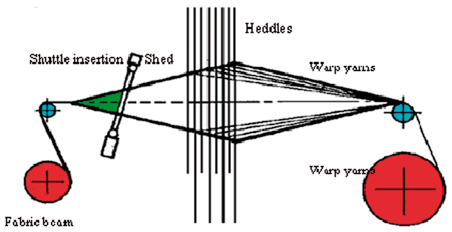
The weaving of warp interlock fabrics is more complex than traditional 2D weaving. Each warp yarn is woven with a large angle of penetration inside the structure and crossed every warp and weft yarns for each layer. This involves more crimps inside the fabric contrary to 2D samples. All of these observations lead to increase in the short fiber formation and create a weakness zone in the yarns, as we can see on the Figure 6.
Illustration of short fibres due to yarns evolution during the weaving process.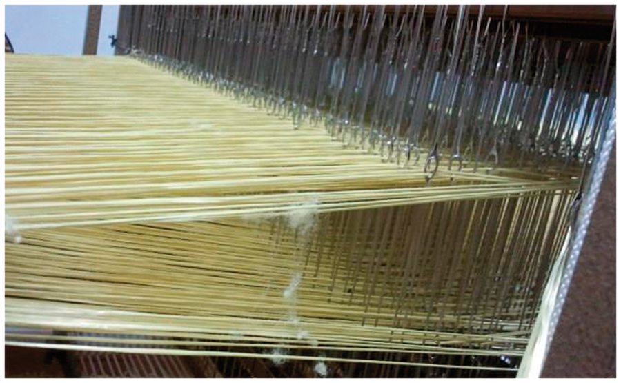
Due to previous observations, twisting on yarns was applied to limit this degradation and increase the tensile properties and the cohesion of fibers. Considering the results of Bateup et al. [5] and Xu et al. [6], we have decided to modify the warp yarns distribution and apply a number of associated beams to the number of shafts used to manufacture the fabric (see Figure 7). Combined with a slow fabric production, the control of warp yarns tension leads to reduce the damages on yarns. Thus, each yarn has a warp evolution independent to other yarns. The warp tension is controlled by each beam, the shed motion is more regular, and yarns are placed one above the other in the through-the-thickness structures (see Figure 8). The influence of weaving structure is a main cause of the yarn degradation due to the previous parameters. For this reason, we have decided to test three kinds of interlock structures, with three warp directions inside the structure: the O/L, O/T, and A/T. After the weaving, we have randomly pulled out yarns inside the warp layers (see Figure 9) and in weft layers (see Figure 10). If we compare the three interlock structures, the O/T fabric does not damage the breaking elongation of the warp yarn compared to the two other structures, contrary to the weft yarns. The breaking tenacity is less degraded in the A/T and O/L structures. To resume, the warp and weft yarns of A/T structure are the less damaged. This could be explained by the fact that the warp and weft yarns are inserted progressively inside the 3D structure and not directly from the top to the bottom of the 3D structure.
Beam system to control the tension of yarn. Lack of fibrillations during the shed formation. Influence of weaving process on mechanical properties of warp yarns for each interlock structure. Influence of weaving process on mechanical properties of weft yarns for each interlock structure.


Discussion on the yarn damage values for each step of the weaving process
In Figure 11, a complete summary of the results obtained on yarns is shown and helps to better understand the degradation process in yarn properties. We note that adding twists on yarn give more resistance. In fact, we have an increase of about 6% of the tensile strength value but a loss of breaking elasticity around 10%. Regarding the influence of twisting on breaking tenacity and modulus, the increase of mechanical properties may be explained by the fact that twisted yarns involve a fiber orientation and consolidation which lead to additional resistance. Regarding the breaking elongation, as the fibers have been twisted, they are not able to slip inside the structure and to absorb the strain. We can observe this phenomenon during the test; an untwisted yarn will break step by step whereas twisted yarn breaks suddenly.
Comparison of mechanical properties for each step of the study.
During the warping process, several damages on warp yarns can be done. A loss of elongation of approximately 6% and 2% for the breaking tenacity and modulus has been observed.
Inside the O/L structures, the warp yarns are bound in layers twice together. The yarns have a lot of undulations and crimps inside the fabric. This can explain the results which show a loss of tensile strength of 10% and 11% for the breaking elasticity. The weft yarns being in contact with one row of warp yarn in each layer of the structure do not penetrate the entire structure and have few undulations. Nevertheless, we must take into account the influence of the weft yarn preparation which is wrapped on small rolls that allow the insertion of weft yarn. So we observed a loss of properties around 2.5% for the breaking tenacity and Young modulus and nearly 5% for elongation.
In O/T binding, the warp yarns either bind the entire thickness of the fabric or are placed longitudinally between the columns of weft yarns. Contrary to the O/L binding, the weft yarns have major degradations. Indeed, we observe a loss of value of about 9% for the breaking tenacity and 12% for elongation. Concerning the warp yarns, the loss is 5% of value for the breaking tenacity. Compared to the weft yarns, the warp yarns have lost 19% of the yarn modulus value after the weaving process.
Inside the A/T structures, the warp yarns go through the entire thickness of the structure that can induce a lot of crimp between the warp and weft yarns and many undulations. The results for the warp and weft yarn are similar for the breaking tenacity and elongation. We observe a loss up to 5% for the tenacity and 8% for the elasticity for the two kinds of yarns.
Conclusion
The study concerning the addition of twist on high-performance multifilaments yarns led us to reduce their loss of mechanical properties during all the steps of the weaving process. The fibrous materials considered are Kevlar 29® para-aramid yarns.
The warp interlock weaving process is complex and several operational devices need to be adapted for the weaving loom. Moreover, the total number of warp yarns which is higher compared to the 2D weaving structure induces a lot of yarn-to-yarn friction during the weaving process. Thanks to our adapted warp interlock weaving process, decreases on the damage of yarns were achieved (maximum of damage measured is less than 20%). Indeed, all the adapted and specific devices inserted on the weaving loom led us to minimize warp and weft yarn damages. Compared to the other studies, the maximum damage value for warp yarns in warp interlock structures are less than 20% for the Young modulus and 12% for breaking elongation. Concerning the breaking tenacity, we obtain a loss of 10%. This value is well significant when we consider that for a 3D weaving process with glass fibres, previous studies find fibres damages around 50% for the Young modulus. This study shows predominantly that the para-aramid yarn damage is not so high with an optimized twisted value. Some specific improvements dedicated to devices on the weaving loom are more beneficial for the tensile properties of warp interlock structures (see also Figure 11).
Moreover, thanks to this work, different yarn behavior damage has been revealed concerning different warp interlock structures. Indeed, weft yarns in O/L multilayer fabric exhibit better behavior for the breaking tenacity compared to other structures. However, the warp yarn is subjected to a lot of damage, unlike O/T warp yarns. Regarding the breaking elongation, weft yarns for all structures exhibit almost the same behavior. The O/T warp yarns keep almost the initial breaking elongation and were not influenced by the woven architecture. Finally, the Young modulus for the weft yarns is almost the same for each structure, contrary to the warp yarns where the Young modulus in O/T structure is lower compared to the O/L structure. We can also note that A/T bonding caused less damage than the other structures (see also Figure 11). These results could be explained by the yarns distribution and evolution. Indeed, in A/T structures, there is an equilibrated evolution between warp and weft yarns contrary to the other structures. In O/L and O/T structures, the warp yarns evolutions between the layer or through the layers lead to have more frictions between yarns and more evolution of warp yarns on the beams.
In future works, local and in-situ measurements of the mechanical properties of the 3D-woven structure will be possible using sensor yarns especially suited to detect tensile strength difference and elongation. Moreover, these measurements could help us to determine the effect of twist on the final mechanical properties of the material used. It would be also interesting to correlate some yarn friction on the weaving machine to the resulting degradation.
Footnotes
Funding
Financial support is brought by the DGA, grant no. 2008 34 0015.
Acknowledgment
We acknowledge the DGA and Nexter Systems for their kind help to carry out the study in good conditions.