
Abstract
The three-dimensional weaving process enables to produce near-net shaped complex preforms used as reinforcement of composite materials. However, the lack of knowledge on the mechanical behaviour of these three-dimensional woven structures may restrict their use for composite material. To fill this gap, we have tempted to highlight their specific mechanical properties according to their endogenous parameters. Based on these different architectures produced on the same weaving loom, several non-impregnated coupons have been mechanically characterized in all the directions of the three-dimensional warp interlock fabrics with quasi-static tensile tests in warp and weft directions as well as in-plane shear tests. According to our analyses, it has been revealed that the combination of several parameters as the woven pattern, the end and pick densities and the presence or not of stuffer warp yarns inside the three-dimensional fabrics may significantly influence the mechanical behaviour of the three-dimensional warp interlock architectures.
Keywords
Introduction
Due to the inclusion of through-the-thickness binding yarns, three-dimensional (3D) fibre reinforced composites have several advantages over traditional two-dimensional (2D) composites such as elevated fracture toughness, better inter-laminar fracture toughness, higher damage tolerance, impact resistance and higher tensile strain-to-failure [1–4]. In order to obtain 3D preforms, the through-the-thickness fibres can be inserted using a variety of textile techniques which include 3D weaving, stitching, tufting, knitting and braiding [5–7]. The 3D weaving process also enables the composite manufacturer to produce near-net shape complex preforms which are best suited in high-tech industrial domains [8]. Consequently, 3D-woven composites made from E-glass, carbon, polyester or aramid fibres are the subject of recent studies [9–14] for their applications in high-tech industrial domains, such as automotive and aerospace industries and for instance fan blades developed by Warren et al. and Dambrine et al. [4,15]. If these papers are dedicated to the identification of mechanical properties of 3D-woven composites and to the development of simulation tools to describe and compute 3D-woven composites properties, few studies concern the influence of 3D-woven architecture on these mechanical properties at dry scale, before impregnation. Based on the large amount of published data, Mouritz [16] has previously presented the influence of some Z-binder parameters (angle and depth of binding yarns, volume content, diameter of Z-binders) on out of plane and in-plane mechanical properties. But the influence on the mechanical properties of all the parameters defining a 3D-woven structure [17–21], especially before impregnation, has not been completely studied. Moreover, from published results on 3D-woven composites mechanical properties, it is difficult to dissociate the influence of the composite process parameters to the fibrous reinforcement parameters. Consequently, this paper concerns on one side, the study of the weaving on a rapier dobby loom dedicated to produce thick 3D warp interlock fabrics and, on the other side, the mechanical characterization of these non-impregnated reinforcements made with flax roving. Driven by the standards demanding more environmental-friendly products [22,23], the use of natural fibres as reinforcements for composites materials has increased significantly in the last decade [24]. Natural fibres such as flax offer low carbon footprint and biodegradability advantages combined with a high specific stiffness at a low-cost [25–28]. Weaving methods of 3D-woven preforms are studied in textile literature [17,20,21,29,30], especially from E-glass, carbon, polyester or aramid fibres but few papers have detailed the feasibility to realize these 3D-preforms from flax fibres. From flax roving, this paper describes the manufacturing of twelve 3D warp interlock fabrics produced by varying different weaving parameters (in-plane woven architecture of layers, angle and depth of binding yarns, pick density, etc.). If tensile properties of natural yarns are generally described at fibre scale [31–38] or tow scale [39–44], studies identifying these properties at the preform scales are mainly focused on 2D-structures obtained by weaving [45,46] or by braiding [47]. At this fabric scale, in-plane mechanical characteristics are attached to the formability properties by experimental tests conducted in tensile or in-plane shear [48–51]. But, in these quoted works’ tests, the link between preform architecture parameters, such as pick/end densities, type and angle of the binding warp yarn in the thickness or weave diagram of binding warp yarns, and mechanical properties is not clearly established. The objectives of this paper are therefore to describe the feasibility to realize 3D warp interlock fabrics from flax tows and to analyse the influence of architectural parameters of these 3D-reinforcements on their mechanical performance. In the first section of this study, the used flax roving is described and, the weaving process of 3D warp interlock fabrics, minimizing yarns degradation, is detailed. Characterization methods especially fitted to non-impregnated textile structure are then introduced. In the second section, a detailed description of 3D warp interlock fabric architecture is given based on their main and principal endogenous parameters [17]. In the last sections, textile and mechanical properties are experimentally identified and compared based on accurate statistical analysis.
Materials and methods
The architecture of the tow consists in an assembly of slightly entangled, almost aligned flax (Linum usitatissimum L.) fibre bundles along the tow longitudinal axis, as described in previous works [43,52,53]. The properties of the rovings without twisting are presented in Table 1 and curve in Figure 1.
Load-Strain curve of flax rovings without twisting. Properties of flax rovings without twisting.

To avoid less fibrous degradation during the weaving process, the flax rovings have been produced with 35 twists per metre in Z direction on a Twistec machine [38]. After this twisting step, the flax roving, with an initial lenticular cross-section shape on its bobbin, has been named a flax yarn with an elliptic cross-section shape.
3D-warp interlock weaving process
With this twisted flax yarn, in which cohesion between fibres is improved, the warping and the weaving steps have been carried out. First, the warping step has been performed on a sampling warping machine (SUZUKI NAS-5S) (Figure 2(a)). Then, the weaving machine used to produce 3D warp interlock fabrics was a rapier dobby loom (DORNIER HTVS 4/S) (Figure 2(b)) equipped with a second warp beam for stuffer warp yarns. The chosen weaving reed has five teeth/centimetre with a feeding of two yarns/tooth which led to an end density of 10 warp yarns/cm.
Weaving process: (a) sampling warping machine (SUZUKI NAS-5S); (b) Rapier dobby weaving machine (DORNIER HTVS 4/S).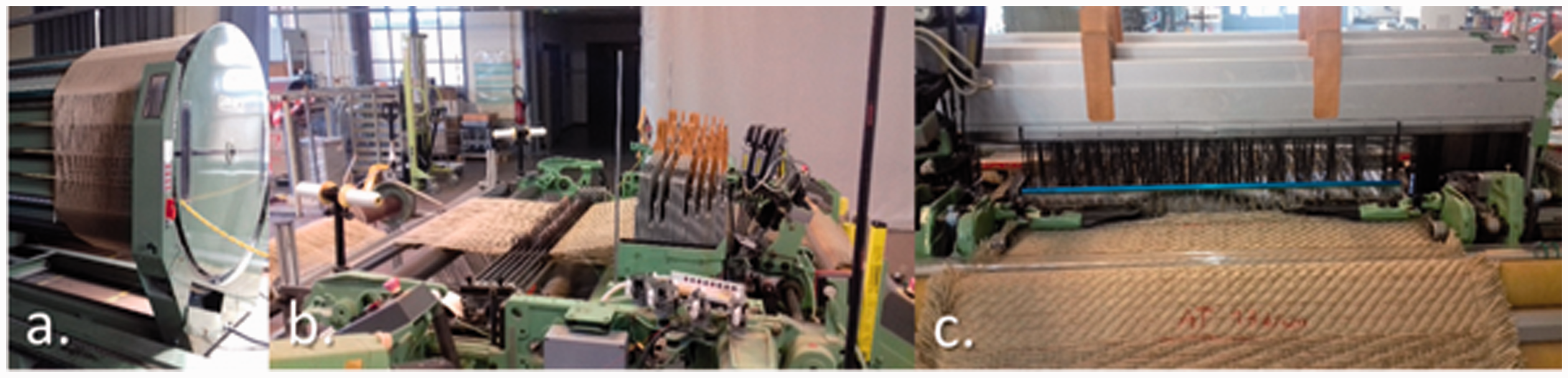
Many defects may occur during the 3D weaving process as described in Lee et al. and Lefebvre et al. [54–57]. By the same method, during the weaving process of flax yarns, defects have been caused due to the different values of the end and pick densities. Dynamic friction between flax yarns and several loom parts as the heddles eyes and the weaving reed tooth causes many damages on the warp yarns during the shedding and beating-up steps, such as abrasion of yarns or broken fibres [58]. These damages have been observed, in Figure 3, and can cause yarns breakages. To avoid any breakage of yarns and minimize the degradation by dynamic friction, warp tension and weft insertion speed have been adapted to ensure a continuous and efficient production.
Observed damages on flax yarns during weaving process.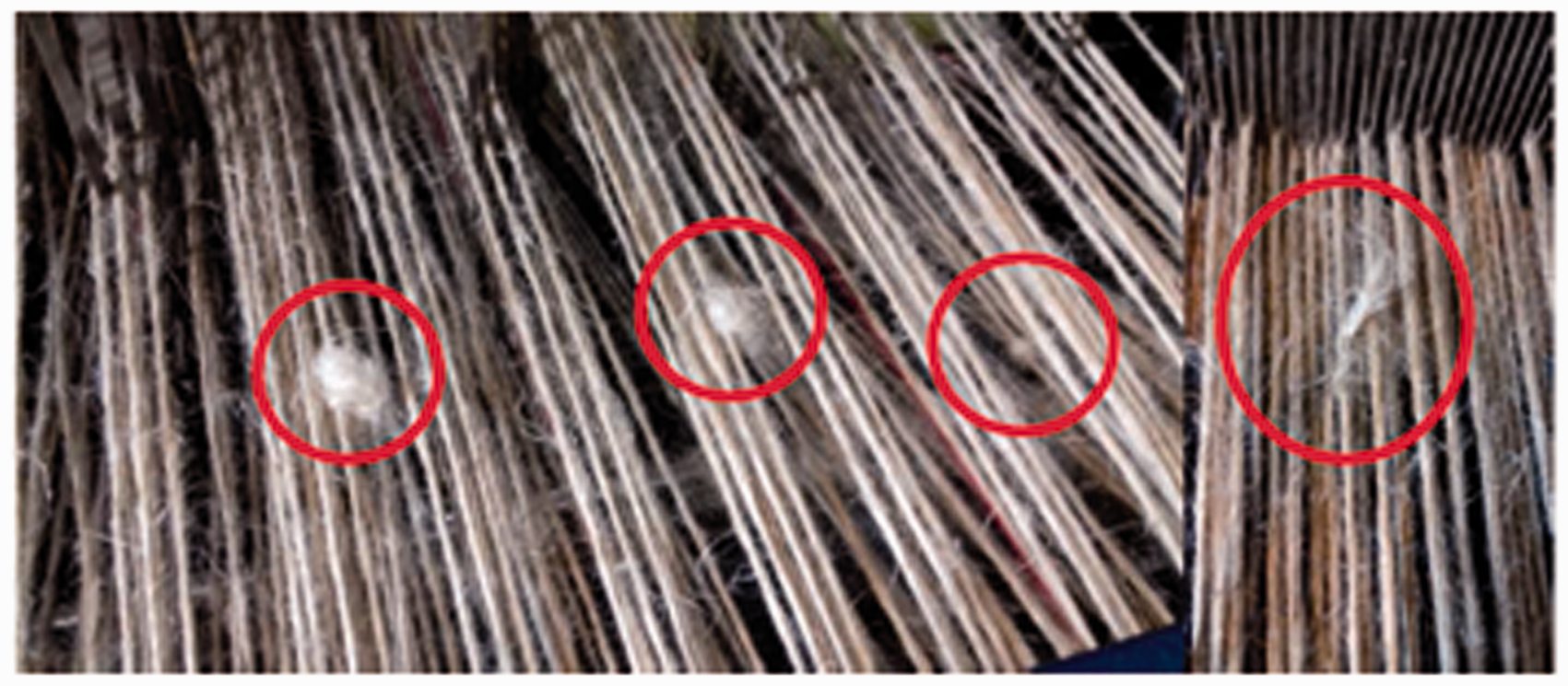
Description of characterization tests
Several characterization tests have been performed on each 3D warp interlock fabrics. Concerning textile parameters, warp and weft shrinkages, fabric thickness and areal weight have been identified.
The warp and weft shrinkages have been calculated for each warp and weft yarns of each different 3D warp interlock fabric architectures following the same path inside the woven pattern. For the 3D warp interlock fabrics with stuffer warp yarns, the binding warp yarns and the stuffer warp yarns have been considered separately. The length measurements of yarns have been done according to the standard NF ISO 7211-3 [59], and shrinkages, in each direction, have been calculated by the relative difference between lengths of the yarns inside the fabrics and lengths of extracted yarns from fabrics. The thickness has been measured according to the standard NF EN ISO 5084 [60] and the areal weight according to the standard NF EN 12127 [61]. These two tests have been conducted on 15 samples per architecture. For mechanical tests, the fabric sample sizes have been fitted to 300 mm × 50 mm according to the standard EN ISO 13934-1 [62] required for tensile tests to be done both in warp and weft directions using a tensile bench (INSTRON 250 kN) with a preload of 10 N and a crosshead displacement rate of 5 mm/min during the preload and 100 mm/min during the tensile test. To avoid any slippage of the 3D fabric inside the clamping jaws, tested coupons have been impregnated with epoxy resin, according to contact moulding process, at their additional 50 mm edges of each side, so the length between the jaws has been kept to a constant value of 200 mm. To ensure that no resin flow into the gauge section, a space between the extremity of the gauge section and the impregnated section was reminded without resin.
Description of 3D-warp interlock fabrics
Several 3D warp interlock fabrics were produced for this study: some fabrics without stuffer warp yarns and some fabrics with stuffer warp yarns. The addition of stuffer warp yarns inside the woven pattern tends to bring more rigidity in the thickness direction of the 3D warp interlock fabric. The produced 3D warp interlock fabrics architectures, listed in Table 2, have been defined with some main endogenous parameters as detailed in Boussu et al. [17]. The first two letters are associated to the angle type of the binding warp yarn in the thickness (A: Angle, O: Orthogonal), and to the type of the binding warp yarn in the thickness (L: layer to layer; T: through the thickness). The next three numbers are, respectively, the number of superposed weft layers, the binding step, which represents the number of weft yarns between two interlacing points of the binding warp yarn located in the same layer, and the binding depth which represents the number of weft yarns layers linked with the binding warp yarn. The surface fabric weave diagram (for example Satin 5 shift 2) aims at defining the evolution of the next warp yarns located in the same top position of the fabric. In Figure 4, the different binding warp yarns (in blue colour) are numbered from 1 to 8 along the warp yarns axis and the first layers of weft yarns are named respectively a1, b1, c1 and d1 along the warp yarns axis. The second and third layers of the 3D warp interlock fabrics are represented from the top to the bottom of the woven structure along the layers axis. Between each layer, inter-ply positions can be defined, which help to locate binding or stuffer (if exist) warp yarns in the thickness of the structure using a matrix scheme described in Boussu et al. [17].
Positions of the different warp and weft yarns inside a 3D warp interlock fabric. Characteristics of produced 3D warp interlock fabrics.

For instance, the 3D warp interlock fabric without stuffer warp yarns and entitled O-L 3 4-2 Satin 5 means an
The woven structures have been chosen to have the widest overview of structural parameters and to avoid any change of the drawing-in diagram during the weaving process. In this paper, only seven structures will be presented and analysed. Those structures, shown in Table 2, are a wide overview of 3D-woven fabrics. The first three structures are made of three layers and without stuffer warp yarns, with the same binding depth and different weave diagrams. The other structures have four layers, stuffer warp yarns and have the fourth binding types existing: one O-L, one O-T, one A-L and one A-T. The end density has been kept constant to 10 ends/cm for all the fabrics and the pick density has varied according to the fabrics architectures. Inside the 3D warp interlock fabric, the distribution of warp yarns is one stuffer warp yarn for one binding warp yarn.
Description of mechanical tests
Considering the quasi-static tensile test applied to fabrics both in warp or weft directions, the typical tensile load versus strain curve of 3D warp interlock fabrics without stuffer warp yarns can be represented in Figure 5. The tensile load/strain curve is characterized by a first non-linear part, associated to the weave loss of fabrics, and followed by a linear part [45,46,63–65]. To compare several architectures with different yarn densities, the load is related to the number of yarns subjected to the tensile load. The parameters extracted to these curves, in warp and weft directions, are the maximal load, the strain at maximal load and the weave loss, as described in Figure 5. To study the influence of the fabrics crimp of several architecture and responsible of the weave loss of fabrics during the tensile load, the weave loss parameter is defined as the strain value deduced from the tensile curves at the intersection of the linear part and the abscissa axis, as schematized in Figure 5. The weave loss corresponds to the stretching of the yarns inside the fabric under the tensile load. Indeed, yarn behaviour is composed of two main parts: first, a stretching in the direction of the applied load and second, a tensile strength in the same direction.
Example of tensile load/strain curve for 3D fabrics (O-L 3 4-2 Satin 5 shift 2 in weft direction).
For some 3D warp interlock fabrics architectures, the tensile behaviour is characterized by two peaks in the tensile curve, as schematized in Figure 6, and as exhibited for others fabrics [66]. The appearance of a second peak is due to a significate difference in yarn consumption (warp shrinkage) inside the fabric structure: yarns are not all stretched in the direction of applied load at the same time and breaking occurs in two times. The tensile behaviour will be analysed for the two peaks, with the same parameters, as described in Figure 6.
Example of tensile load/strain curve for 3D fabrics with two peaks (O-L 3 4-2 Satin 5 shift 2 in warp direction).
The in-plane shear behaviour of these 3D warp interlock is identified by bias-extension test [67–71] which tends to be a pure shear stress, compared to the picture frame test [72], due to the fact that the yarns of the sheared zones are free at their edges and consequently there is no tension applied on yarns [67]. Samples have the same dimensions than those used for tensile tests, but warp and weft tows are initially orientated at 45° in the applied load direction. Like for tensile tests in warp and weft directions, tested coupons have been impregnated with epoxy resin, according to contact moulding process, at their additional 50 mm edges of each side, to avoid slippages inside the clamping jaws, so the length between the jaws has been kept to a constant value of 200 mm. During these tests, samples breaks, whereas this phenomenon do not occur with 2D fabrics, so the parameters of the in-plane shear behaviour are analysed from bias-extension test load–displacement curves, as the maximal load, the strain at maximal load and the locking strain in shearing, as schematized in Figure 7(a). During the test, a video camera records the deformation of the coupon which will help to calculate the evolution of the in-plane shear angle (γ). This angle is analytically computed from the extension of the specimen [67], denoted d. In equation (1), D is the length of the sheared (central) zone of the sample. The in-plane shear angle is also experimentally measured during the test with ImageJ software. From the ‘bias-extension test load–in-plane shear angle’ curve, the locking angle can be deduced, as presented in Figure 7(b). This is a limit value of shear angle without any out-of-plane wrinkles of the fabric structure [73–75]
Bias-extension load curves in function of a) strain b) in-plane shear angle (A-L 4 3-2 Twill 4).

Tensile results of 3D warp interlock fabrics
Tensile curves of 3D warp interlock fabrics without stuffer warp yarns.
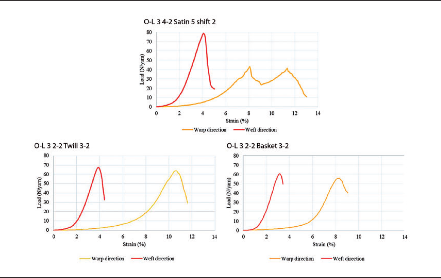
Tensile curves of 3D warp interlock fabrics with stuffer warp yarns.

Analysis of 3D warp interlock fabrics properties
After the production of the different types of 3D warp interlock fabrics, several observations could be made. Based on the different types of binding and stuffer warp yarns as well as the weft yarns, the determination of warp and weft shrinkages may also reveal the different type of mechanical behaviour of yarns during the weaving process. At the end, the calculation of the resulted areal weight of 3D warp interlock fabrics may better highlight the influence of the weaving process as the pick density is directly driven by the weaving loom.
Observations of warp and weft shrinkages
Shrinkage in each direction of the fabric is an important parameter on its mechanical behaviour, especially in the first part of the tensile load–strain curve as introduced in Figure 5. The results of warp and weft shrinkage average values for 3D warp interlock fabrics without stuffer warp yarns are shown in Figure 8, with standard deviation. For O-L 3 2-2 Twill 3-2 and O-L 3 2-2 Basket 3-2, the warp shrinkage of the binding warps yarns, located between the two inter-plies (as explain previously in Figure 4), is similar. For O-L 3 4-2 Satin 5, the warp shrinkage of binding warp yarns of inter-ply 1 is more important than those of binding warp yarns of inter-ply 0. This can be explained by the weaving process parameter of the weft concentration above the warp yarns: in this architecture, there are more weft yarns above the warp yarns of inter-ply 1, so warp binding yarns in this inter-ply are more crimp and thus the warp shrinkage is more important. For O-L 3 2-2 Twill 3-2 and O-L 3 2-2 Basket 3-2, yarn concentrations are more balanced, which explain similar values for warp shrinkage of the two inter-plies.
Warp and weft shrinkages of 3D warp interlock fabrics without stuffer warp yarns.
For 3D warp interlock fabrics with stuffer warp yarns, warp and weft shrinkage values are given in Figure 9. Significant differences between the fabrics can be observed. For O-L 4 1-3 Twill 3, warp shrinkage for binding warp yarns is more important than those of stuffer warp yarns. For the other fabrics, the warp shrinkage for binding and stuffer warp yarns is similar, whereas warp shrinkage for stuffer warp yarns should be near zero. In theory, stuffer warp yarns should be straight inside the fabric and then their shrinkage should be close to zero. But, during the weaving process, the stuffer warp yarns are located on a separated beam whose tension is not well controlled. Thus, stuffer warp yarns are not well stretched, and the concentration of yarns above them explains the variability of their shrinkage between the fabrics. The warp shrinkage for a through-the-thickness binding type is more important than the warp shrinkage in a layer-to-layer binding type. In fact, in a through-the-thickness binding, every warp yarns cross the entire fabric whereas in a layer-to-layer binding, warp yarns cross only few layers. The addition of stuffer warp yarns has no impact on the weft shrinkage. The warp shrinkage of 3D warp interlock fabrics with stuffer warp yarns is less important than without stuffer warp yarns: there are less spaces between the layers of weft yarns (due to the presence of stuffer warp yarns) so warp yarns have less space for crimp.
Warp and weft shrinkages of 3D warp interlock fabrics with stuffer warp yarns.
Observations of areal weight
Areal weight of 3D warp interlock fabrics tends to have an influence on the bending property: a higher areal weight will lead to a higher bending rigidity [76]. Values for areal weight are represented in Figure 10 and are compared with pick density and thickness values. When stuffer warp yarns are added in the 3D warp interlock fabric, areal weight and thickness values increase. Moreover, when the pick density increases, the areal weight and the thickness increase. Indeed, when the pick density increases, the warp yarns will crimp more inside the fabrics, the warp shrinkage will also increase, and thus the thickness.
Areal weight, pick density and thickness of 3D-warp interlock fabrics.
Mechanical behaviour of 3D-warp interlock fabrics
The 3D warp interlock fabrics have been submitted both to warp and weft directions tensile tests as well as 45° orientation of coupons for bias tests. The mechanical behaviour is studied on non-impregnated fabrics.
Tensile behaviour
The tensile behaviour in each direction (warp and weft) is analysed with parameters characterizing the tensile curve (Figure 5). Values of maximal load are reported in Figure 11, with eventually, values for the second peak. To compare 3D warp interlock fabrics with different pick densities, the maximal load values (Figure 11) are given in N/yarn. The phenomenon of the double peak occurs for two 3D warp interlock fabrics: O-L 3 4-2 Satin 5 and O-L 4 1-3 Twill 3. As explained previously, a difference in warp shrinkage of yarns is behind this behaviour: for O-L 3 4-2 Satin 5, Figure 8 shows that warp shrinkage for binding warp yarns in inter-ply 0 and in inter-ply 1 is not the same whereas for O-L 4 1-3 Twill 3, Figure 9 shows a difference between warp shrinkage of binding warp yarns and stuffer warp yarns. In both the structures, yarns with lower warp shrinkage will be stretched earlier, and then they will break and create the first peak. In the same time, yarns with higher warp shrinkage will continue to stretch and will break later, during the second peak. When this phenomenon occurs, the density of yarns with low warp shrinkage and high warp shrinkage is the same. Consequently, values at each peak are similar.
Maximal Tensile load in warp and weft directions.
Tensile load in the weft direction remains higher than the load in the warp direction, except for O-T 4 3-4-Twill 3-3. In warp direction, the value of maximal load (computed by yarn) of the tested fabric has been found very near to the value of tensile load of the yarn (47.8 ± 2.1 N, given in Figure 11). In the warp direction, for 3D warp interlock fabrics with stuffer warp yarns, the layer-to-layer binding has a maximal load lower than the through-the-thickness binding. In fact, the through-the-thickness binding contributes to the cohesion of the fabric and its resistance. In the weft direction, it is the opposite phenomenon: the layer-to-layer binding has a maximal load upper than the through-the-thickness binding. The layer-to-layer binding type better links the weft yarn layers between them. For 3D warp interlock fabrics without stuffer warp, maximal load in warp and weft direction is balanced, when considering the standard deviation. Fabrics with higher warp shrinkage (Figures 8 and 9) have a higher maximal load in weft direction: the crimp of the yarns tends to increase the tensile behaviour in the weft direction. A high warp shrinkage refers to an important crimp of warp yarns around the weft yarns, which will increase the cohesion between the fibres inside the weft yarns and thus bring more resistance to the fabric in weft direction. Moreover, when the maximal load in the warp direction increases, the maximal load in the weft direction decreases. Inversely, when the pick density increases, the maximal load in the weft direction increases.
In Figure 12, weave loss is reported in each direction as well as second peak values. Expressed in strain (%), this parameter dissociates the beginning (non-linear) of the tensile curve to the linear part, as defined in Figure 5. Shrinkage values (in %) are superposed to these values. Most of the fabrics have a similar trend as regard the weave loss values and the warp or weft shrinkage values. Thus, the weave loss is the stretching of the yarns under the tensile stress. For the 3D warp interlock fabrics with double peak, the second peak appears when the difference of warp shrinkage is superior to 2%. The warp weave loss at the first peak matches with lower warp shrinkage. At the second peak, the warp loss matches with the higher warp shrinkage, when there are a significant difference in warp shrinkage. For the major part of the fabrics, the warp yarn shrinkage must be considered to predict the weave loss in the warp direction and the weft shrinkage to predict the weave loss in the weft direction.
Weave loss in warp and weft directions.
For all fabrics, values of strain at maximal load in each direction are represented in Figure 13, with eventually values at the second peak. As it occurs in Figure 12, shrinkages were superposed. The previous analysis linking the influence of the shrinkage on the weave loss is identical for these strain values at maximal load, but with significant higher values. The strain at maximal load follows the evolution of the yarn shrinkages, especially the warp yarns. For 3D warp interlock fabrics with orthogonal binding, strain at maximal load in warp direction remains higher than values in weft direction, but for fabrics with angle binding, warp and weft shrinkage have similar values. In orthogonal binding, binding crosses straight the weft layers, whereas in angle binding warp, yarns crimp between the weft layers and thus yarn consumption is lower, which explain lower strain at maximal load values.
Strain at maximal load in warp and weft directions.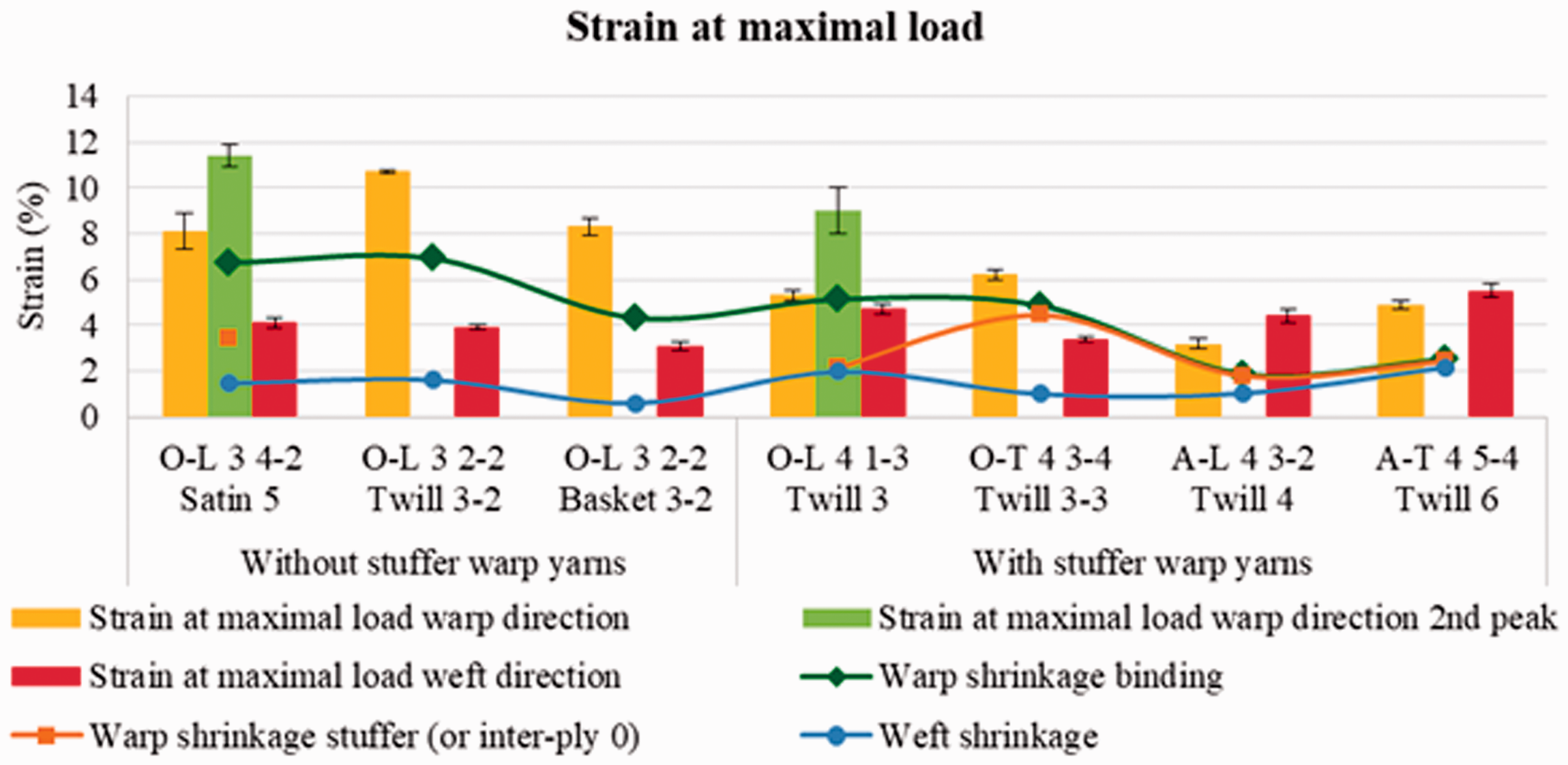
In-plane shear behaviour
Figure 14 represents different evolutions of the tested sample during the bias-extension test. These tests characterized the break localized in the pure shear zone (central part of the coupon) for all specimens. Under the applied load, yarns are subjected to pure shear deformation. But binding points slide inside the fabric and consequently warp, and weft yarns slide between one to another until the fabric rupture. This breaking phenomenon is little detailed in literature associated with the in-plane shear behaviour [67]. From the ‘bias extension load-strain’ curves, three parameters are especially analysed: the maximal bias extension load, the value of the locking strain and the strain associated to the breaking load. During this test, in-plane shear angle is measured in pure-shear zone and also geometrically computed from the displacement of the sample. Locking angle is deduced, as explained previously (Figure 7(b)).
Bias extension test of flax 3D-warp interlock fabrics.
For all 3D warp interlock fabrics, values of maximal bias-test extension load are reported in Figure 15.
Maximal load from bias-extension tests of 3D-warp interlock fabrics made with flax yarns.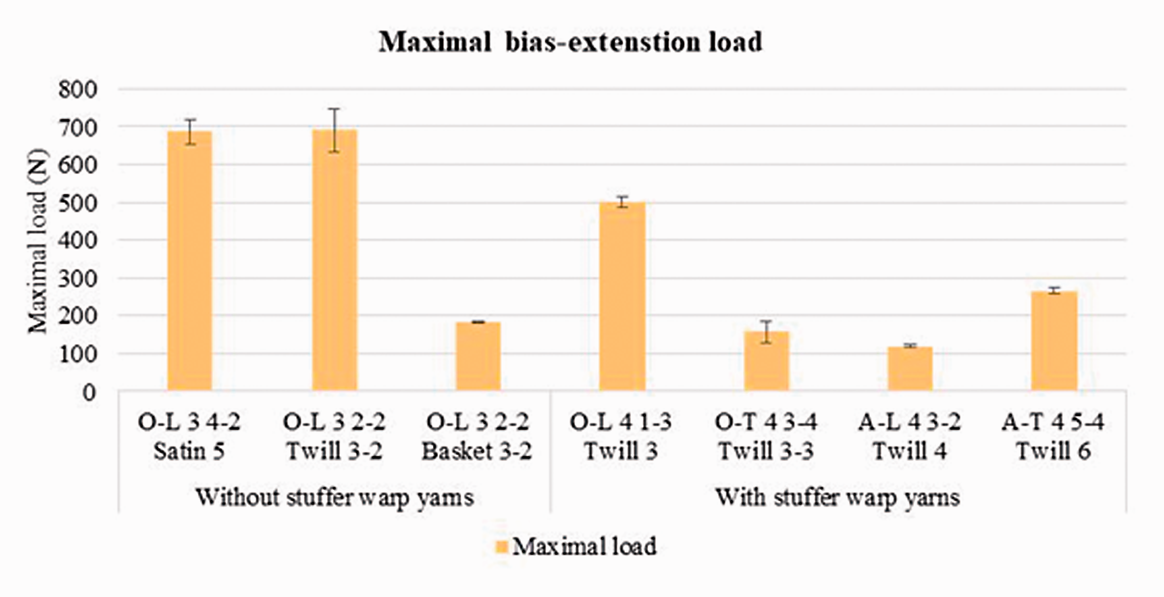
According to these results, it seems difficult to conclude on the influence of binding warp yarn types (layer-to-layer or through-the-thickness) on these maximal bias extension load values.
For all 3D warp interlock fabrics, maximal and locking strain values are represented in Figure 16. The locking strain in shearing corresponds to the longitudinal strain when the yarns are in contact (before this strain, the yarns rotate without being in contact); the maximal strain is the associated value to the maximal load. These parameters follow the same trend for each 3D warp interlock fabrics. The in-plane shear behaviour is characterized by large strain which can be a maximum of 30% for the locking strain and 41% for the maximal strain, which correspond to an extension of 60 and 80 mm of samples, respectively. All the fabrics with stuffer warp yarns have lower strain values compared to fabrics without stuffer warp yarns.
Maximal and locking strains from bias-extension test of flax 3D-warp interlock fabrics.
Figure 17 reports the locking angle values, defined as the value of in-plane shear angle from which yarns are in contact. Locking angle is computed as explained in Figure 7(b). Pick density is used to explain locking angle: the more the warp yarns are, the higher the locking angle is. In-plane shear angle is related to the shear strain which is not the same component than the strain values, reported in Figure 13, which are associated to the longitudinal displacement of samples during the bias-extension test. For 3D warp interlock fabrics without stuffer warp yarns, the higher the locking strain is, the less the locking angle is. Weave diagram with the lowest locking angles is basket weave. Denser the weave diagrams are, more difficult the yarn's motions are and less important the locking angle is. Architectures with stuffer warp yarns exhibit higher locking angles. Compared to 2D fabrics, locking angles of these 3D warp interlock fabrics can reach significant values (near to 40°).
Locking angle during the bias extension test.
Conclusion
This experimental study has associated both the production of 3D warp interlock fabrics made with flax yarns and the identification of their physical and mechanical properties in order to analyse the influence of the manufacturing parameters on these characteristics. From flax roving, the weaving of seven different 3D warp interlock fabrics has been done without any major damage due to fibrillation, demonstrating the feasibility to achieve complex architectures from flax roving. These different architectures have been more detailed using endogenous parameters. Shrinkages, areal densities and thicknesses measurements have shown the dependence of these properties from manufacturing parameters (pick/end densities, angle and type of the binding warp yarn in the thickness, weave diagram of binding warp yarns). In-plane mechanical behaviour of these non-impregnated 3D warp interlock fabrics has been experimentally identified. For the tensile behaviour in the warp direction, specific double-peak behaviour has been highlighted for 3D warp interlock fabrics with stuffer warp yarns. A first break of some warp yarns appears followed by a recovery of the load. This phenomenon depends on the difference of shrinkage values between layers. These results have also shown the dependence between both orientations: when the tensile load in warp direction increases, the maximal load in weft direction decreases and inversely. The influence of the warp shrinkage associated to the choice of binding architecture parameters as layer-to-layer or through-the-thickness on the weave loss during tensile tests has been revealed. Considering the in-plane shear behaviour of these 3D warp interlock architectures, a specific behaviour until the break has been observed as well as the dependence of the cohesion between layers with the binding points associated to the binding architecture. The in-plane shear behaviour of these 3D warp interlock fabrics is characterized by large strains and significant locking angle which tend to be helpful during the forming step using complex punching shapes.
Future works will be oriented on the analysis of the preforming behaviour of these 3D warp interlock architectures and also the comparison of the mechanical behaviour with the same architectures achieved with others raw materials (like high modulus polyethylene, carbon and E-glass).
Footnotes
Acknowledgements
Authors would like to thank the French Company DEPESTELE for providing us the flax rovings used in this study.
Declaration of conflicting interests
The author(s) declared no potential conflicts of interest with respect to the research, authorship, and/or publication of this article.
Funding
The author(s) received no financial support for the research, authorship, and/or publication of this article.