
Abstract
Three dimensional (3D) warp interlock fabric becomes a promising structure due to its good mechanical performances. However, its complex manufacturing process can cause severe yarn damage and affects its overall final performances. The current study addressed the effects weaving process and warp yarn ratios on the multi-filaments yarn degradations and its mechanical performances while 3D warp interlock fabric manufacturing. Four different 3D warp interlock variants having similar fabric architecture, and yarn densities but different warp yarns interchange ratios were manufactured using 930dTex high-performance multi-filament (Twaron® f1000). The multi-filaments yarns at different weaving processes were tested for their tensile properties. The results show that the average tensile strength of twisted yarns show a decrement of 5.68% as compared to the bobbin yarns. Meanwhile, warping process also showed a 16.11% maximum breaking load reduction as compared to the bobbin yarn. Besides, the tensile strength of binding yarn after weaving process for samples 3D-8/0, 3D-8/4, and 3D-8/8 was reduced by 12.79%, 5.22%, and 14.22% respectively as compared to the yarn after warping process. In conclusion, yarn degradation inside the 3D woven structure was affected not only by the various process parameters but also by the type of fabric architecture made with different warp yarn ratios. These phenomena ultimately bring a great influence both on the yarn and overall mechanical performance of the final products. For this, further studies are planned to investigate the multi-filaments yarn degradation effect on the ballistic performances fibrous material as it is directly linked to the yarn performance.
Keywords
Introduction
Nowadays, besides the conventional 2D woven fabrics and UD laminates, three-dimensional (3D) warp interlock fabrics are widely used for the development of complex shapes as fibrous reinforcement composite parts for various technical applications. This is not only due to its excellent moulding behaviour but also its good mechanical performances. Various studies have also suggested 3D warp interlock fabrics can substitute the conventional 2D fabric structures in the field of ballistic protection due to its low shear rigidity, ballistic performance [1–3], good elastic behaviour properties [4] and extraordinary moulding properties [5–10]. Indeed, before any applications, a complete investigation and understanding of its mechanical behaviour of the 3D warp interlock fabrics are very critical. For this purpose, various researchers have studied the mechanical behaviour of the3D warp interlock fabrics structures considering various internal and external parameters. For instance, the mechanical properties of the 3D warp interlock fabric and its composite do not only depend on the fabric structure [11,12] but also the combinations of various factors including fibre [13,14] and yarn [15,16] properties, areal density [17–19], fabric thickness, etc. One of the studies has also proved that the mechanical behaviours of 3D warp interlock fabric are significantly affected by the combinations of the weave pattern, yarn density, and presence of different warp yarns types inside the fabric [20]. Besides the internal parameters of the fabric, due to its structure complexity, its mechanical behaviours have been also affected by the weaving process. Such a process could bring yarn damages that cause fibre degradation due to yarn-to-yarn friction and abrasions of the yarn by the different static guides and dynamic metallic parts during yarn preparations (twisting, warping, drawing etc.) and weaving stages. Various solutions including reducing loom speed, minimizing the yarn friction within the yarn and metallic parts, reducing the yarn tension controller can be used to reduce the fibre degradation of yarns to produce 3D thick woven structures as 3D warp interlock fabrics. Besides, few researchers have tried to study and understand the influences of the different stages of the weaving process considering various factors including material type, yarn locations, 3D woven architectures type; on the yarn degradations and mechanical properties of warp and weft yarns inside the 3D warp interlock fabrics. One of the studies investigated and tried to understand the effects of various weaving process of 3D warp interlock p-aramid fabrics on the yarn degradation and its loss of mechanical properties of both weft and warp yarns. The result shows that maximum mechanical property reduction has been carried out in the warp yarn (10%) than weft yarns (6%) [21]. Further, extended researches have been done to investigate the effect of different 3D warp interlock architecture on its yarn damage during weaving process. Through-the-thickness (O-T) and layer-to-layer (O-L) 3D warp interlock architecture revealed outstanding result on limiting the warp and weft yarns damage respectively. Another researcher have also studied and analysed the effect of weaving process on the tensile properties of air-entangled textured polyester single and multiple yarns ends by ravelling from the produced plain, ribs and satin woven fabrics based on experiment and modelling methods. According to the result, the tensile strength of the yarn from the fabrics was recorded less than the bobbin yarn due to the result of yarn degradation during weaving process. Besides, the developed regression model revealed the effects of the number of interlacement and crimp ratio on the warp and weft yarns tensile strengths [22]. The influences of the woven fabric geometry on the fibre degradation were also investigated while manufacturing 3D warp interlock fabric structure. The study shows that up to 35% of tenacity loss for S2-glass yarns were observed due to fibre degradation [23]. Similarly, the effects of the weaving process on the fibre degradations during three-dimensional (3D) fabric while manufacturing from continuous glass fibre yarns were investigated [24]. Different yarns were considered at various weaving stages to examine both its fibre damage and residual tensile properties. According to the study, friction among the yarns and yarns with the loom machinery part results higher abrasion damage with approximately a reduction in yarn strength of between 30 and 50% depending on the type of yarn. Besides, yarn breakage during weaving process brought slight reduction on yarn stiffness but huge loss in yarn strength. Based on the another study on the effects of the weaving on the degradation of glass yarns and the tensile properties of 3D orthogonal woven composites, higher damages of yarns during 3D weaving process were found due to abrasion (30% of reduction in dry woven yarn tensile strength) and breakage resulting from the friction between the yarns against different loom parts [25].
In the research work of [26], the effect of yarn damage and the induced mechanical performance of fibre tows and their corresponding composites during the weaving of two commercially-available carbon fibres were investigated. Reductions of the yarn tensile property have mainly occurred only when the fibres were highly damaged during the weaving process. Besides, due to the availability of higher fibre crimp, multilayer woven fibre was highly deteriorated as compared to unidirectional and non-woven fibre tow composites. Another study has also investigated the fibre damage of the three types of commercially available carbon fibres on different stages of the process including the bobbin, through the creel and loom mechanism and the final woven fabric while manufacturing the 3D multi-layers woven structure. Besides, its effect on the mechanical and physical performance of the fibre tows in the woven composite was also analysed [27]. Similarly, the influences of the weaving process on the quasi-static and dynamic properties of aramid yarns (virgin T1040 Twaron® yarns and yarns extracted from plain-woven T717 Twaron® fabric) were also investigated before the mechanical loading applications. During the test, a Split Hopkinson Tensile Bar device and high-speed camera to record the phenomenon were employed. Based on the result, both yarns show similar sensitivity, an increase in strain rate and tensile strength, but a decrease of the failure strain. However, virgin yarns revealed a less failure strain but higher strength and stiffness than woven yarns. Besides, more broken fibres were observed due to fibre damage during the weaving process [28].
Besides the above phenomenon, the involvement, movement, and constituents of the different warp and weft yarns greatly affect the overall properties of the fabrics. According to [29], stuffer and binding warp yarns could delineate the longitudinal and through-the-thickness properties of the fabric respectively. Whereas, weft yarn also helps not only to describe the number of the layer but also determine the transverse properties of the fabric. Therefore, understanding the combined effects of different yarn composition inside the fabric and the production process while producing 3D warp interlock fabric on the yarn degradation is then very important. This will also give a better insight for producing the intended fabric with less fibre degradation and better mechanical properties for the final material solutions. Thus, the current research work aims to investigate and relate the effects of both the production process (yarn preparation and weaving) and the internal structure of 3D warp interlock fabrics (different warp yarns interchange ratio) on the yarn degradation and its mechanical performances. As mentioned earlier, four different 3D warp interlock fabric architectures based on different binding and stuffer warp yarns interchange ratios were designed and manufactured. Experimental testing of yarns at different stages of the weaving process and fabric types were investigated and analysed.
3D Warp interlock fabric production and experimental methods
Basic principles and definitions of 3D warp interlock fabrics
Even though different researchers have defined and classify the 3D warp interlock fabric [30–32], it was clearly described based on orientation and interlacing angles of the different weft layers by binding warp yarns [29]. Based on the criteria, the fabric was classified into four categories namely: Orthogonal - Layer-to-layer (O-L), Orthogonal - Through-the-thickness (O-T), Angle - Layer-to-layer (A-L) and Angle - Through-the-thickness (A-T). The binding warp yarn was used to interlace either for complete or different weft layers of the structure following a diagonal direction in the A-T and A-L configurations respectively. Whereas, the different binding warp yarns tried to link the entire thickness or some of the layers following an orthogonal direction for O-T and O-L configurations respectively. Due to this different structure inside the fabrics, the 3D warp interlock fabric provides good mechanical properties and deliver good ballistic performance along with good delamination properties as compared to the traditional 2D fabrics and UD laminates [33–37]. This is mainly due to its different structure inside the fabric that could give various advantages including low shear rigidity and excellent formability behaviours [5]. Besides, the denotation nwft, x and y represent the number of superposed weft yarns layers of 3D warp interlocks fabric, the binding step and the binding depth respectively as shown in Figure 1. The binding steps are usually represented by the number of weft yarns between two interlacing points of the binding warp yarn located in the same layer. Normally, the step is considered as constant for all the binding warp yarns inside the 3D warp interlock fabric architecture. Whereas, the binding depth indicates the number of weft yarns layers which are allied by the binding warp yarn. The binding depth of the different warp yarns can be constant or variable data.

Representation of the four classes of 3 D warp interlock fabrics types with binding parameters and number of layers [29].
Manufacturing processes of 3D warp interlock fabrics
For a better analysis of the effects of fabric architecture and weaving process on multi-filament yarn degradation during the weaving process, four possible 3D warp interlock orthogonal–layer-to-layer (O-L) p-aramid fabrics were designed and manufactured.
The intended fabrics were engineered considering different binding and stuffer warp yarns interchange ratios on the fabric repeat unit of the structures. The warp yarn interchange ratios or percentages are namely; 8:0 (100% binding warp yarns and 0% stuffer warp yarns - Sample 3D-8/0), 8:4 (66.7% binding warp yarns and 33.3% stuffer warp yarns - Sample 3D-8/4), 8:8 (50% binding warp yarns and 50% stuffer warp yarns - Sample 3D-8/8) and 4:8 (33.3% binding warp yarns and 66.7% stuffer warp yarns - Sample 3D-4/8). Both the 3D graphical representation and weave pattern of the repeat unit for the different 3D warp interlock fabric with different warp yarn interchanging ratios are shown in Figure 2. The commercial TexGen® and DBweave® software’s were utilized to design the 3D geometrically model and the peg plans of the fabric respectively. A 930dTex high-performance multi-filament (Twaron® f1000) yarn was used to manufacture the different 3D warp interlock fabrics. Such multi-filament yarns claimed to have a higher level of ballistic protection due to their unique kinetic energy absorption through improved yarn working surface. The ultrafine filaments in the yarn also provide an extraordinary softness for a higher level of comfort for the wearer. Besides, all the fabric structure was manufactured considering the same architecture (Orthogonal - Layer-to-layer, O-L), weft layers number (5 layers), ends/cm/panel densities (48) and picks/cm/panel densities (50). The complete multi-filament yarn and fabric characteristics are illustrated in Table 1.

The 3 D graphical model representation and weave pattern of the repeat unit for the 3 D warp interlock fabric with different interchanging ratios between binding and stuffer warp yarns.
Specification of high-performance para-aramid multi-filament yarn [38] and the produced 3 D warp interlock fabrics.

Before weaving, all the multi-filaments yarns were twisted with 25 twists per meter in Z direction using Twistec® machine to avoid any cohesion of the non-twisted multi-filament yarn during the weaving process. The twisted yarns were winded on the warp beams (having 50 cm width) using the dedicated warping machine to be used as the warp yarn. The intended different 3D warp interlock fabric structures were then woven using prototype-weaving looms equipped with semi-automatic weft insertion and flat take-up roller of the fabric, located in ENSAIT-GEMTEX laboratory. Such a weaving loom mainly help to minimize the filament degradation between yarns and different weaving machine parts through optimizing the warp yarns’ tension difference during the weaving process.
The 24 Dobby lifting frame is also selected to accommodate the 24 different warp yarns evolutions inside the 3D woven structure. Each warp beam was associated in the respective Dobby lifting frame both to manage the warp yarns’ consumption and the applied warp yarn tensions. However, while weaving the different 3D warp interlock structure, the binding and stuffer warp yarn yarns were winded onto separate beams for better warp yarns control during the weaving process. Besides, an adapted creel was also used to contain all of the 24 warp beams (Figure 8(a)), where the entire warp yarns are guided inside individual ceramic holes (Figure 8(b)) allowing a clear distinction of each warp yarn in the thickness of the woven structure. This also allows a reduction of the yarn-to-yarn frictions (Figure 8(c)). Normally, the tension load applied on warp beams is individually spread to each warp yarns, where the selection was given by lifting heddles located in the 24 Dobby frames. The shed opening, resulting from the vertical motion of each Dobby frame, allows the pick-in of the weft yarn and, finally, the beat-up of the weaving reed to achieve the fabric forming of 3D warp interlock fabrics.
Tensile testing of the yarns
The yarn at the different stages of the warping and weaving preparations till to the fabric stage has been carefully drawn and tested using a universal testing machine (INSTRON 8516) with a 5 KN load cell at a tensile speed of 50 mm/min (equivalent to 0.34 inch per second) as shown in Figure 3. The tensile test of the individual yarn specimens was carried out based on the NF EN ISO 2062 standard. In general, ten yarns of replica for each test of the weaving stages of the 3D warp interlock fabric architectures were considered for better results repeatability. The individual yarn specimen was cut at a total length of 250 mm. The nominal distance between the two adapted clamps of the tensile testing machine to maintain the yarn was 200 mm. The machine is normally composed of two special upper and lower steel clamps dedicated to such kinds of tests to avoid any slippage while testing. Besides, additional sticky adhesive material on the inside part of the modified clamps was used for better clasping the multi-filament yarn to limit their slippages. Before using the p-aramid multi-filaments yarns, measurements were carried out not only to check the given data but also to have the same measurement method throughout the different steps of the investigation. The testing process for each specimen was carried out until yarn fracture takes place. Besides, the Coefficient of variation (CV) of the tensile strength at maximum load for each stage of the sample data was also computed to determine if there is any uncontrolled error occurred in the samples during the experimental test. Based on the analysis, the CV (%) values were found 6.3% 7.2%, 8.34% and 9.4%, for tested samples at bobbin, after twisting, warping and weaving stages respectively. This generally indicated that during the test unwanted factors within the sample were controlled. The values during the test also can be considered as variation due to the natural variation within the tested samples. Besides, the variation within the different stages was also more or less in similar ranges.

Uniaxial yarn tensile testing device set-up.
Results and discussions
In general, the main interest of this research aims at defining the degradation of multi-filaments yarns while producing the different 3D warp interlock fabrics. Normally, the loss of some multi-filaments yarn quality could bring great influence on the overall performance of the produced 3D woven fabric structure while used in industrial applications. For example, the ballistic performance of fibrous material is directly linked to the yarn performance. During ballistic impact, if the high-speed projectile faces the degraded yarn, it will not only absorb less energy but also it might be penetrated before the projectile stopped as compared to a virgin yarn. Thus, investigating the degradation of all the yarns according to their locations inside the 3D woven structure helps to understand indirectly the yarn friction behaviour according to several influencing factors (architecture, the ratio of stuffer and binding warp yarns, etc.) and process parameters (end and pick densities, drawing-in diagram, etc…). This section will then discuss and better understand the effects of the weaving process while weaving different types of 3D warp interlock fabric. This will mainly help on the process parameters to be adjusted to reduce the yarn friction and its resulting degradation and keep its initial strength inside the 3D woven structure.
Tensile properties of yarn at initial and bobbin storage
To understand this phenomenon, the tensile tests on the yarns at the bobbin were carried out to measure the real performance of para-aramid yarns at the beginning. The yarns were tested without applying the twisting process. As shown in Table 1, the strength at Break [N] of the yarn from the manufacturer was given as 225 N with the elongation at break values of 3.45%. However, the individual and average tensile values of the yarns specimens on quasi-static tests are given in Figure 4. According to the results, the measured individually yarns on the bobbin (untwisted) using the MTS machine shows lower strength at break (201 N) values as compared to values from the Teijin Aramid.

Tensile (load vs. displacement curves) of the tested p-aramid yarns for (a) each specimen and (b) average values at bobbin storage for manufacturing 3 D warp interlock fabrics.
Effect of yarn preparation (twisting process and warping) on mechanical properties of yarns
Before the weaving process, the yarn has to be prepared in different stages depending on the various parameters of the produced fabrics. Among the various stages, yarn twisting, winding and warping of the warp yarn into the beam are the most common steps. However, great care should be taken during such a yarn preparation process to reduce the degradations of the yarn. In the twisting process, the yarn passes through various static guides and dynamic machine parts as shown in Figure 5. The friction between the yarn and the machine part could cause yarn degradations and affects its final mechanical properties. On the contrary, twisting the yarn might also bring additional strength and reduce the defibrillation of multi-filaments at yarn to yarn contacts [21]. Normally, the twisted yarn possesses a lower breaking elongation due to the multi-filaments cohesion inside the yarns. In our study, we only consider similar twist level (25 twists per meter (TPM) in the Z direction) to bind the multi-filaments while producing all the 3D warp interlock fabric. This helps to comprise the resulted tensile strength versus the non-alignment of multi-filaments inside the yarn. Besides, applying the same twist level (25 TPM) provides not only to properly bind the multi-filaments but also helps to produce an appropriate fabric structure for ballistic impact performance investigation for women body armour applications.

(a) Twisting machine and (b), (c) and (d) different yarns guide.
Normally, the twisting level of the yarn intends to increases the mechanical properties due to the involvements of fibre orientation and consolidation which lead to additional breaking resistance. However, according to our investigation, it is noted that the twisted multi-filaments yarn shows almost similar breaking resistance than the untwisted multi-filaments yarn. In fact, according to our investigations, the twisted multi-filaments yarn mechanical behaviours (average tensile strength) values were decreased by about 12 N (5.68%) than the bobbin yarn. This might be due to the degradations of filaments in the yarn which arise due to the friction between the static and dynamic twisting machine parts and the yarn during the twisting process. Figure 6 show the tensile strength versus elongations of the yarn curve at the untwisted (bobbin) stage and its comparison after the twisting and warping process. Besides, the twisted yarn average breaking elongation was recorded with around 2% (4 mm) fewer values as compared to the bobbin yarn. This is due to as the fibres are twisted; it tends to resist the slippage among each other inside the yarn structure to absorb the yarn strain. Based on the tensile testing result, unlike the twisted yarn which breaks suddenly, untwisted filaments in the yarn breakage were broke out one by one.

Effect of yarn preparation (twisting and warping process) on the mechanical properties of the yarn.
As shown in Figure 6, approximately 2.4% and 0.4% a strain elongation loss were observed as compared to the bobbin and after twist yarn respectively. Besides, a 16.11% (44 N) and 10.5% (22 N) maximum breaking load reduction has been observed as compared to the yarn at the bobbin and after twisting process respectively. Another yarn preparation process, warping and beaming process, might also influence the mechanical properties of the warp yarn. This is mainly due to the friction created between the warp yarn and the different warping machine parts during warping and beaming process as shown in Figure 7. According to the result, the warping and winding processes also decrease the mechanical properties of the yarn. Based on these observations, the yarn has been damaged due to yarn friction during the beaming process (Figure 7(a)), warping process by the rotary plates (Figure 7(b)), and at the static guides (Figure 7(c)).

(a) Warping machine and process, (b) and (c) different warp yarn guides.
Influence of weaving process on mechanical properties of yarns
The weaving process is the main stage in the fabric production process which mainly includes the three main stages of weaving such as warp yarn selection (shedding), insertions of weft yarn in the shed (picking) and beating-up of the inserted weft yarn to the fabric formation area by the weaving reed (beat-up). Moreover, the weaving process also involves other auxiliary processes called the drawing-in, tying-in, warp let-off, warp tensioning and take-up of finished fabrics. However, the involvement and movements of both the primary and the secondary weaving process depend on different parameters, including material type, material finishing, fabric type, fabric structure, fabric thickness, and density etc. At this fabric manufacturing stage, both the warp and weft yarns pass through great frictions not only with various parts of static and dynamic loom parts such as yarn guides, lifting heddles, beating reeds etc., but also friction among the different layers and neighbour yarns as shown in Figure 8. Generally, such frictions could severely damage the yarn while handing by both manually and the appropriate speed of the process. Additionally, as mention in the introduction, weaving of 3D warp interlock structures would be also more complex and faces lots of friction between the yarn and different machine parts as compared to the traditional 2D fabric weaving. This is because, depending on the different structures, each warp yarn inside the structure tends to go through the structure with an angle crossing the weft and warp yarns of each layer. The tight and complex interchange of warp yarns for each interlacing (picks) creates high frictions mainly among the different yarns.
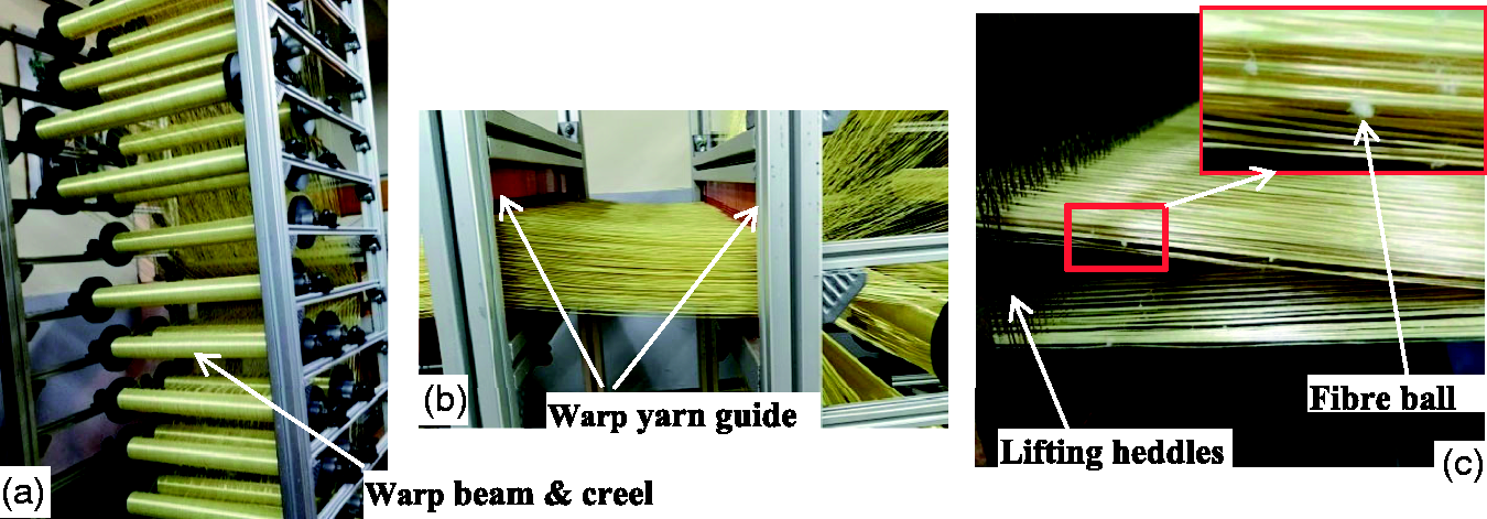
Weaving set-up on the dobby loom, (a) 24 warp yarns’ beams arrangement in the creel, (b) individual warp yarn guide devices and (c) shed formation and its yarn fibrillations.
Besides, the beating of the inserted warp yarn inside the weft layers could create an accumulation of fibrillated short fibres (as fibre ball) during the beating-up process. This ultimately creates thinner and weaker yarns which also affects its final mechanical behaviours. For a better analysis of the effects of the weaving process on the yarn degradations and its final mechanical properties, different yarns at different stages were tested.
The multi-filaments yarn at bobbin, twisting, warping and weaving process was carefully drawn and considered. For the yarn after weaving, both the binding warp yarn at the first row and weft yarn of the first layer of sample 3D-8/0 were investigated. In general, the weaving process could greatly affect the tensile strength and its breaking elongations of the tested yarns. This is also supported by our investigations. The mechanical behaviours of both the warp and weft multi-filaments yarns have been greatly affected by the weaving process as compared to original (bobbin) yarn and after warping process. For better comparison, Figure 9 shows a comprehensive summary of the investigation results on the tensile behaviours of multi-filament yarns at the bobbin stage, after twisting process, after warping and weaving process (both warp and weft). This could benefit to better realize the effects of the weaving process on filament degradation and yarn mechanical properties. However, as it’s clearly shown in Figure 9, among the two common woven yarn types, the warp yarn has been severely degraded and lost much of its mechanical behaviours as compared to the weft yarn. This is since warp yarns have a higher tendency to generate higher friction among themselves and with various guides and loom parts as they pass for weaving operations than weft yarns. For example, a warp yarn has shown decrements of 28.9% (61 N) and 12.79% (27 N) maximum tensile strength as compared to the yarn at the bobbin and warping process respectively. Besides, its tensile elongation has been reduced by 2.415% as compared to the bobbin yarn. On the contrary, the tested weft yarn after weaving possesses a reduction of 19.4% (41 N) and 3.32% (7 N) of the maximum tensile load than the yarn at the bobbin and warping process respectively. Its tensile elongation values were also slightly reduced by 0.3% and 2.16% than yarn after warping and bobbin stages. Figure 10 show the different types of damages yarn filaments images after tensile testing.
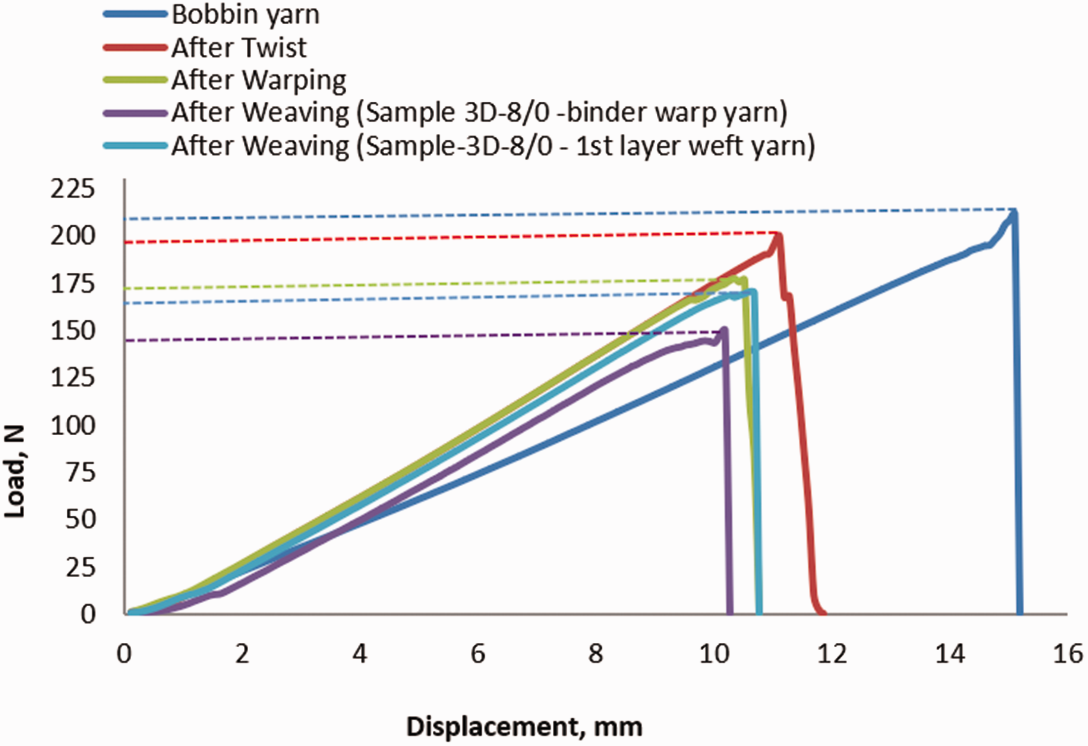
Effect of weaving process on the warp and weft yarns mechanical properties of 3D warp interlock fabrics (considering the first weft layer and sample 3D-8/0 for warp yarn).

Different damages of multi-filament yarn after tensile testing.
Influences of warp yarn ratios inside 3D warp interlock fabric architecture on yarn degradations and its mechanical properties
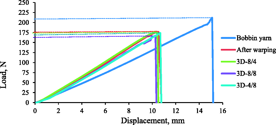
The weaving process of the 3D warp interlock fabric structure is difficult due to the complex interlacing and movements of yarns inside the structure. However, its complexity also varies depending on some parameters including fabric architecture type, involvements of different yarns and weaving mechanism. Apart from the weaving structure [21], the interchange ratios of the warp yarns inside the fabric structure are one of the main cause of the yarn degradation. In this section, it was found very important to study the effects of different warp yarns interchange ratios inside the 3D warp interlock fabric structure both on the yarn degradations and its mechanical behaviours while manufacturing. This study has proposed to manufacture and test four different types of 3D warp interlock structures made with different warp yarns interchange ratios. While weaving, the same number of warp beams (24 beams) was used for all fabric structures to control the warp tension. Moreover, each beam was then associated one to one with the lifting shafts for independent warp yarn evolutions during manufacturing all the fabric structures. The positions of warp yarn in the selected 3D warp interlock structure depend on the interchange ratio of the warp yarns (the stuffer and binding). For example, sample 3D-8/0 involves 100% (8 yarns per weave repeat) of binding warp yarns. This indicates that all the warp yarns are binding with zero stuffer warp yarns inside the structure. On the contrary, sample 3D-8/8 holds an equal number (8 yarns each per weave repeat) of binding and stuffer warp yarns. Moreover, depending on the 3D warp interlock fabric structure the warp yarn might bind different layers of weft yarns. This could lead to the non-uniform distributions of the warp yarn among the developed fabric structure. However, for uniform and better analysis of the effect, the first rows of binding and binding/stuffer warp yarns were considered. Figures 11 and 13 show the influences of warp yarns ratios inside the 3D warp interlock fabric during the weaving process on the mechanical properties of both binding and stuffer warp yarns. Based on the observations, 3D warp interlock fabric structure having the same warp yarns ratios, sample 3D-8/8 shows higher yarn tensile strength reductions as compared to other variants. Whereas, sample 3D-4/8 revealed lower or almost no reduction on the maximum tensile strengths on the binding warp yarns. For example, samples 3D-8/0, 3D-8/4, and 3D-8/8 show reductions of 5.22%, 12.79%, and 14.22% tensile strength of binding warp yarns respectively as compared to the tested yarn just before weaving process (after warping). The first reason for the increased warp yarn degradation could be the involvements of higher ratios of binding warp yarns within the fabric weave repeat unit for sample 3D-8/8 fabric structure than sample 3D-4/8. For example, sample 3D-8/8 involves 8 binding warp yarn evolutions within the fabrics’ repeat unit; whereas only 4 binding warp yarn evolutions are placed for sample 3D-4/8. This by itself ultimately brought higher friction even among the different neighbouring multi-filament yarns. Thus, the friction among the yarns increases the degradations of multi-filaments yarns inside the fabric structure.

Influences of 3 D warp interlock variants during the weaving process on mechanical properties of binding warp yarns.
The other reason which could influence the mechanical properties of the yarn would be the presence of waviness in the multi-filaments yarns. Normally, the correlation between crimp, fabric structure geometry and its physical behaviour is complex. Therefore, it is very important to investigate and understand the relation between yarn crimp with the tensile properties. For this investigation, the different 3D warp interlock variant with 20 cm length both in the warp and weft direction was prepared. Twenty yarn specimens from each fabric sample were gently removed in the predefined directions and its initial length (length with waviness) were measured with 1 mm precisions. Later, the yarn was fixed on the one end of the machine and unbending (straightened) it under 150cN and measuring its length. The test was carried out according to the standard methods for yarn crimp for woven fabrics (ASTM D3883) using the crimp testing machine (TESTEX). The waviness of the yarn is expressed as the mean difference between the straightened yarn length and crimped yarn thread length as follows:
Cp = yarn crimp (%),
Lo = Straightened multi-filaments yarn length (cm),
Lr = Crimped multi-filaments yarn length (cm).
Figure 12 indicate the yarn crimp percentage for different yarn systems inside the developed 3D warp interlock fabric structures. As shown from the result, fabrics possessing either a lower or higher ratio of binding warp yarn system inside the structure revealed higher binding warp yarn crimp percentage. For instance, binding warp yarn from sample 3D-4/8 revealed higher crimp percentage as compared to other variants. In consequence, the binding warp yarns from sample 3D-4/8 possess lower or almost no reduction on the maximum tensile strengths followed by 3D-8/0. In contrary, the crimp percentages of the stuffer yarn were directly proportional to the warp yarn ratio.

Yarn crimp percentage for the different yarn system inside the developed 3D warp interlocks fabric structures.
Besides, the tensile elongations of binding warp yarns for sample 3D-8/4, 3D-8/8 and 3D-4/8 were increased by 0.375%, 0.79% and 0.577% respectively. On the contrary, the tensile elongations of binding warp yarns in sample 3D-8/4 revealed a reduction by 0.08% as compared to yarn before weaving. While investigating the effects of yarns ratios on the stuffer warp yarns tensile properties, only three 3D warps interlock structures, namely sample 3D-8/4, 3D-8/8 and 3D-4/8 were considered since sample 3D-8/0 has no any stuffer warp yarns in its structure. Based on the result, even though the load versus elongation curve shows a similar trend, the weaving process does not affect both the tensile strength and breaking elongation of the stuffer warp yarns in sample 3D-8/4 as compared to the two other structures, sample 3D-8/8, and sample 3D-4/8 as shown in Figure 13. This means that the stuffer warp yarns of sample 3D-8/4 structure were less damaged due to the involvement of fewer proportions of the stuffer warp yarns inside the structure which ultimately reduce the friction among them. On the contrary, Sample 3D-8/8 shows lesser tensile strength but higher breaking elongations of stuffer warp yarns compared to the other structure.
Influences of 3D warp interlock variants during the weaving process on mechanical properties of stuffer warp yarn.
This increase of degradations might be due to higher proportions of not only the stuffer warp yarns but also binding warp yarns inside the structure. For example, a reduction of approximately 5.65% and 1.9% tensile breaking strength for sample 3D-8/8 and sample 3D-4/8 respectively has been observed. The lower reductions of the tensile strength of sample 3D-4/8 are due to its fewer compositions of the binding warp yarns inside the internal architecture.
However, due to its higher yarn undulations and crimps of yarn inside the fabric, stuffer warp yarn in sample 3D-4/8 shows higher tensile elongations as compared to other fabric structures. Figure 14 shows the image of different (binding warp, stuffer warp and weft) yarns inside the 3D warp interlock fabric structure (3D-8/8) and its corresponding filament microscopic images. As it is shown the binding warp yarn revealed higher undulations as compared to the stuffer warp and weft yarns. Apart from the warp yarns (stuffer and binding), the weft multi-filament yarns inside the fabric structure might be also damaged during the weaving process.

Pictures of the multi-filament yarns inside the 3D warp interlock fabric structure (a) Thickness (side) cross-sectional views of 3D warp interlock fabric (3D-8/8) (b) binding warp yarn (c) weft yarn and (d) stuffer warp yarns with their corresponding filaments’ microscopic images.
However, unlike the warp yarn, the weft multi-filaments yarns’ level of degradations greatly depends on the positions of the yarn in the weft layer inside the different structures. Figure 15 shows the effect of weaving process on mechanical properties of weft yarns which are located on different weft layers inside the different 3D warp fabrics structure.

Influences of weaving process on mechanical properties of weft yarn in different layers of 3 D warp interlock variants.
Based on the observations, similar trends of weft yarn load versus elongations curve was observed regardless of both the structure and positions of the yarn in the weft layer. Normally, the weft yarns of each layer of the structure did not penetrate the entire structure, however, there are only in contact with one row of warp yarns. This leaves lower undulations, degradations, and damages of the weft yarn. In general, compared to the weft yarns, the warp yarns have faced higher yarn degradations and have lost much higher tensile strength.
Conclusions
The current study investigates the effect of the weaving process and warp yarns ratios inside the 3D warp interlock fabrics on both yarn degradations and mechanical properties. Based on the result, the average tensile strength and breaking elongation of the twisted yarn were decreased about 12 N (5.68%) and 4 mm (2%) respectively as compared to bobbin yarn. Yarn warping and winding process also affect the mechanical properties of the yarn. Yarn after warping process loss approximately 2.4% and 0.4% strain elongation and 16.11% (44 N) and 10.5% (22 N) maximum breaking load as compared to bobbin and after twisting yarn respectively. In general, warp yarns are severely degraded and lost much of their mechanical behaviours than weft yarns due to higher friction between the yarn and various loom parts. A warp yarn in the sample 3D-8/0 shown decrements of 28.9% (61 N) and 12.79% (27 N) maximum tensile strength as compared to bobbin and warped yarns respectively. However, the weft yarn of sample 3D-8/0 revealed a reduction of 19.4% (41 N) and 3.32 (7 N) % of the maximum tensile load than original and beam warped yarns respectively. Considering the fabric architecture, sample 3D-8/8 shows higher yarn tensile strength reductions as compared to other variants. In contrary, the weaving process did not affect the tensile strength and breaking elongation of stuffer warp yarns of sample 3D-8/4 as compared to sample 3D-8/8 and 3D-4/8. This is because stuffer warp yarns of sample 3D-8/4 structure were less damaged due to their less involvement inside the structure which ultimately reduces the friction among the yarns. On the contrary, sample 3D-8/8 shows lesser tensile strength but high breaking elongations of stuffer warp yarns due to the higher degradations of fibres with the involvements of higher proportions not only the stuffer warp yarns but also binding warp yarns inside the structure. Even though the weft yarn might also damage during the weaving process, similar trends of weft yarn tensile properties were observed regardless of both the structure and positions of the yarn. This might be due to its less contact with the machine parts and lesser penetrations of the warp yarn row inside the structure which leave lower undulations, degradations, and damages of the weft yarn.
Footnotes
Declaration of conflicting interests
The author(s) declared no potential conflicts of interest with respect to the research, authorship, and/or publication of this article.
Funding
The author(s) disclosed receipt of the following financial support for the research, authorship, and/or publication of this article: This work has been done as part of the Erasmus Mundus Joint Doctorate Programme SMDTex-sustainable Management and Design for Textile project, which is financially supported by the European Erasmus Mundus Program, European Commission.