
Abstract
The current study aims at optimizing nozzle diameter and processing conditions for producing quality Kevlar®/polypropylene commingled towpregs meant for thermoplastic composite applications. ANSYS 3D CFD simulation and various experimental techniques are used for the same purpose. The study also investigates the effect of optimized commingled towpregs on the consolidation quality, void % and flexural properties of the developed UD composites. It is concluded that the nozzle diameter of 7 mm has proven to be ideal for producing quality towpregs as it leads to the formation of high nip frequency at 4.5 bar air pressure. The other nozzle diameters, 3 mm, 5 mm, and 9 mm, performed poorly in forming nips. Among these diameters, the 7 mm nozzle has optimum free space between the internal wall of the nozzle and the feed fibre bundle. This optimum space keeps the filaments within the potential air interaction zone and thus leading to the individual filament displacement and entrapment to form stable nips. The Box-Behnken design expert is used for obtaining ideal commingling conditions. The optimized Kevlar®/PP towpregs are produced using a custom fabricated commingling machine with a 7 mm diameter nozzle at the processing conditions - 4.5 bar air pressure, 2 m/min delivery speed, 3% and 1% overfeed, respectively for Kevlar® and polypropylene (PP). These commingled towpregs are flexible, compact, and regular in structure. These towpregs have the highest nip frequency, nip stability, weavability and homogeneous fibre-matrix mixing quality in yarn cross-section along the length. Using such towpregs makes the textile pre-forming effortless and yields composites with better resin impregnation quality and low void content. The UD Kevlar®/PP composites made through these towpregs offered good consolidation quality with a low void (4.3%). These composites showed flexural strength and modulus of 130 MPa and 28 GPa, respectively.
Keywords
Introduction
The commingling process is versatile, economical and produces flexible and drapble hybrid yarn, also known as towpregs. 1 The commingled (COM) towpregs consist of regularly formed nip and open structures along the length. These towpregs are the raw material for textile pre-forming operations such as weaving, knitting, and braiding. Poorly mingled towpregs would have weak nip stability, meaning loosely entangled filaments at yarn structure. In other words, the cohesion between the two sets of filament bundles is poor due to the lower and weaker interlocking between the filaments. Consequently, the stability of the whole towpregs structure across the length would be affected if such weak nips are present in the yarn structure. When such unstable towpregs structures are employed in textile pre-forming operations, they may undergo de-mingling due to yarn-to-yarn friction, yarn-to-metal friction, or various forces acting on the yarn structure during pre-forming. 2 Eventually, the de-mingled towpregs causes filamentation problems during the pre-forming process leading to yarn breakages, frequent machine stoppages and defective pre-forms. 3 The de-mingling causes the separation of fibre and matrix filaments from the mingling state. As a result, an increased melt flow distance can be seen during melt impregnation. 4 The pre-forms structure made from the de-mingled towpregs with many fibre breakages and fabric defects is not ideal for composite making. Using such defective fabric pre-forms directly affects the consolidation quality and negatively impacts the composites’ performance. 5 Textile pre-forms made from the de-mingled towpregs lead to increased void (%) due to the inferior fibre to matrix impregnation caused by high melt flow distance. 6 Similarly, the broken towpregs in the defective pre-forms act as a weak link, further deteriorating the composite properties. 7 Therefore, the production of stable COM towpregs structure having good nip stability, nip frequency, and mingling quality is of utmost importance.8–12
Air jet nozzle design and process variables of the commingling process significantly influence the production of compact, regular, stable and randomly mingled towpregs structures. 13 Many numerical and experimental studies were conducted on the air texturing and intermingling nozzles. These nozzle designs were optimized in terms of the number of inlets, area of air inlets, angle of inlets, the distance between inlets, length and diameter of the nozzle, and the air pressure used. However, limited research has been seen on the design optimization of commingling nozzles using a 3D simulation approach. Past studies used modified air jet texturing machines with either texturing or intermingling nozzle. Among such studies, Choi et al. 14 concluded that the COM towpregs made by single air inlet texturing nozzle had lower filament damage due to the gentle interaction between air streamlines and carbon fibre. In contrast, the single air inlet intermingling nozzle offered intense air-to-fibre interaction, thus showing good potential in producing towpregs with homogeneous fibre-matrix filament distribution. In another study, Alagirusamy et al. 15 studied the effect of single and multiple air inlet nozzles using 2D computational fluid dynamics (CFD) simulations and experiments. The authors concluded that the three-air inlet nozzle configuration that works on the backward airflow principle offers better towpregs quality over the single air inlet nozzle.
No work has been reported on optimizing the commingling nozzle area (yarn channel). In this aspect, Rewi and Pai 16 studied the optimization of the yarn channel diameter of single air inlet texturing nozzle using 3D simulation. The authors observed that the texturing performance enhanced when the length to diameter (L/D) ratio of the yarn channel was between 8 and 10 and the ratio of the cross-sectional area of the air inlet to yarn channel was 1/4th. In another study, the same research team concluded that the interlacing degree in the hybrid yarns was enhanced when the cross-sectional diameter of the air inlet and the length of the yarn channel were decreased or the applied air pressure increased. 17
Jogur et al. 3 introduced an optimized new commingling nozzle design using a 3D CFD simulation. The authors reported that the developed nozzle consumes less compressed energy and works on the forward airflow principle. This nozzle has the great potential to produce stiff and flexible fibres-based towpregs. 3 However, the nozzle diameter was not optimized with the process parameters in the reported study.
In addition to nozzle geometry, optimizing the processing conditions for producing ideal towpregs is necessary. 18 In this aspect, Mankodi and Patel 19 conducted Box-Behnken experimental design study. The authors concluded that the individual and interaction parameters play a significant role in producing quality COM towpregs. Use of high air pressure with low delivery speed and 1% overfeed offered COM towpregs with better nip frequency, nip stability and mingling quality. In another study, Kravaev et al. 20 reported that the filaments position displacement and fibre-matrix blend quality enhanced greatly with increased air pressure and decreased delivery speed. Hasan et al. 21 revealed that the increase in air pressure up to 5 bar enhanced the blend quality of COM towpregs.
In the present study, nozzle diameter optimization is carried out using 3D CFD simulation and experimental approaches. The nozzle diameter is varied as 3, 5, 7 and 9 mm while keeping other dimensions constant, as reported by Jogur et al. 3 The nozzle efficiency is analyzed with respect to vorticity magnitude (VM), turbulence kinetic energy (TKE), turbulence intensity (TI) and radial velocity (RV). The simulation results are compared with experimental results for validation.
In addition to nozzle diameter, the processing parameters such as air pressure (AP), overfeed (OF) , and delivery speed (DS) are optimized for Kevlar®/polypropylene (PP) towpregs using Box-Behnken design expert. To achieve optimization, different Kevlar®/PP COM towpregs are produced at different process parameters using an in-house fabricated modified commingling machine and analyzed for nip frequency. The towpregs produced at different air pressure are further studied for their nip stability, weavability, flexural rigidity, and yarn structural features. To the best of the author’s knowledge, no studies have been reported on developing optimized Kevlar®/PP COM towpregs for thermoplastic composites applications. Production of such towpregs would be beneficial in minimizing the melt flow distance and void content. The Kevlar®/PP composites made through the optimized nozzle and processing conditions could be used to produce high-performance thermoplastic composites for impact resistance applications. Therefore, in the present study, unidirectional (UD) Kevlar®/PP COM composites are made and investigated in terms of void (%), consolidation quality and flexural properties.
CFD simulation
The use of CFD numerical simulation in optimizing the commingling nozzle not only helps in reducing the capital cost but also demonstrates the effect of airflow on fibre motion by visual means. The technique provides the graphical representation of obtained results in contour profiles, vector profiles and streamlines for deeper analysis. The theoretical knowledge obtained through this technique acts as a reference for improving the nozzle design and quality of produced COM towpregs. 22 In the present study, 3D nozzle domains of different diameters are constructed using Solid Works 2016, ANSYS ICEM, fluent and CFD post 2020 R1, respectively, for mesh grid construction, simulation and analysis data. The structured hexagonal mesh grids of nozzles are generated using ANSYS ICEM. For discretization at all inlets and outlets, O- type topology and at the rest of the domains H- type topology is used. The airflow within the nozzle includes turbulent flow and vortex flow; hence, the K-epsilon (k-ϵ) turbulence model with realizable scalable wall functions is used. The fluid air is assumed to be compressible fluid, following the ideal gas law. Reynolds' averaged momentum and continuity equations along with the energy equation, are used for discretization. The simulation is solved without filament bundles inside the nozzle, as the filaments do not significantly affect the flow behaviour. The assumptions adopted in the present simulation modelling are the same as reported by Jogur et al. 3
Computational domain, boundary conditions and grid convergence test
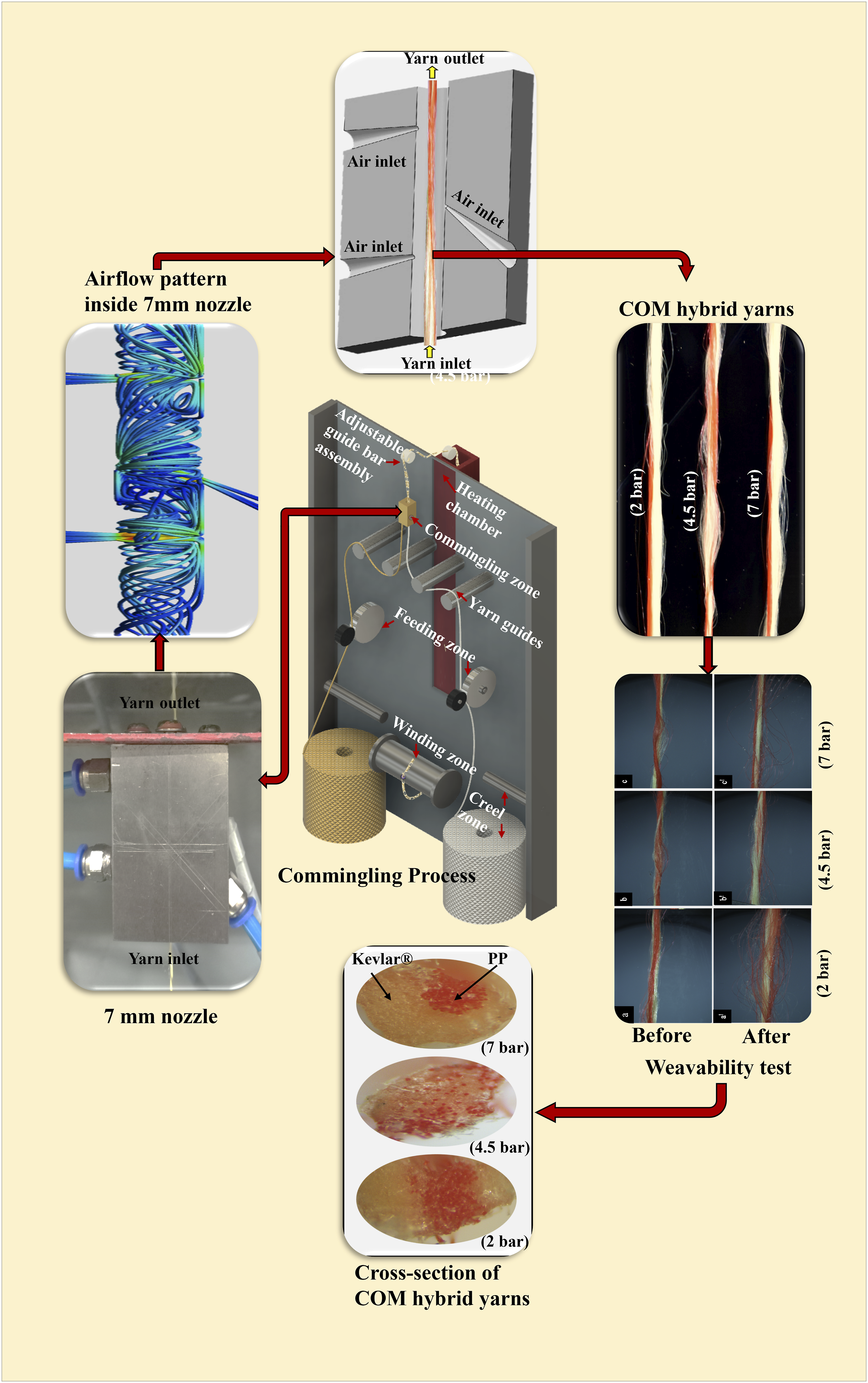
3D physical and computational domains of the commingling nozzle having a 7 mm yarn channel diameter are shown in Figures 1(a) and 1(b). The nozzle consists of three air inlets, out of which two are perpendicular air inlets, and one is an oblique air inlet. The first perpendicular inlet (FPI) is situated at a 19 mm distance from the yarn inlet. In contrast, the second perpendicular inlet (SPI) is positioned at a 10 mm distance from the yarn outlet. The middle oblique inlet (MOI) is mounted precisely at the centre of the nozzle, i.e., at 30 mm away from the yarn inlet and yarn outlet. The MOI is kept at 45° to the nozzle axis facing the yarn outlet. The nozzle domain is segmented mainly as i) pre-opening zone (AA-BB), ii) opening and mixing zone (BB-CC), and iii) secondary zone (CC-DD). The function of FPI and SPI is to open and mix the filament bundles in pre-opening and secondary zones, respectively. The MOI generates high vortex and turbulence at the BB-CC zone, thus providing high mixing of filaments and nip formation.
3
(a) 3D physical domain of 7 mm nozzle diameter with dimensions in mm and (b) computational mesh domain of the nozzle with boundary conditions, (c) Grid independence test showing variation in vorticity magnitude with the change in nodes number.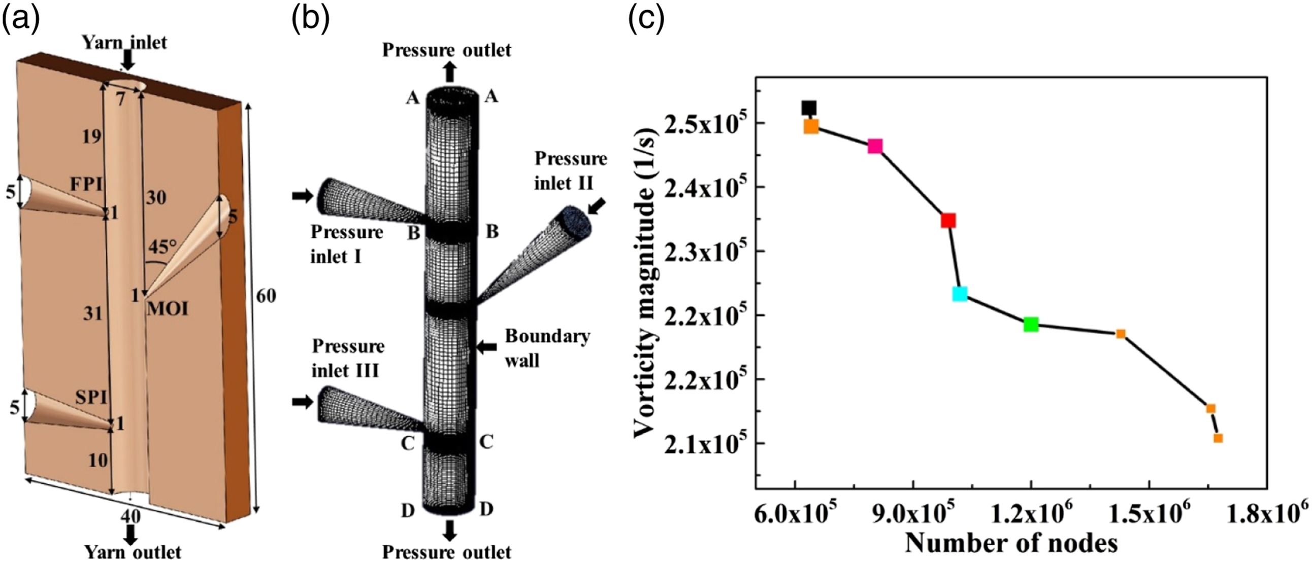
In the boundary conditions, the air inlets FPI, SPI and MOI are assumed to be “pressure inlets” with 7 bar pressure and 300 K temperature. In contrast, the yarn inlet and outlet are “pressure outlets” with atmospheric conditions. A non-slip wall boundary condition is applied at the complete nozzle wall.
The grid independence test (Figure 1(c)) is performed to determine the ideal node numbers to simulate the problem with minimum error and reduced time consumption. It is inferred from Figure 1(c) that the VM decreases with the increase in node number from 6.35E+05 to 1.68E+06 node. However, the VM values remained almost constant between the node numbers 1.02E+06 to 1.43E+06. The stable VM values indicate that the change in the VM is not significant. Therefore, in the present study, the computational grid with 1.20E+06 nodes are chosen for conducting simulation.
Experimental
Fabrication of commingling machine
The newly developed comingling machine is the modified version of the air jet texturing machine that produces textured yarns. The machine has a creeling zone, feeding zone, commingling zone, adjustable yarn guide assembly, heating chamber and winding zone. Different parts of the machine set-up are shown in Figure 2. Different zones of the machine set-up (a) creeling zone, (b) feeding zone, (c) commingling zone, (d) adjustable yarn guide assembly, (e) heating chamber, and (f) winding zone.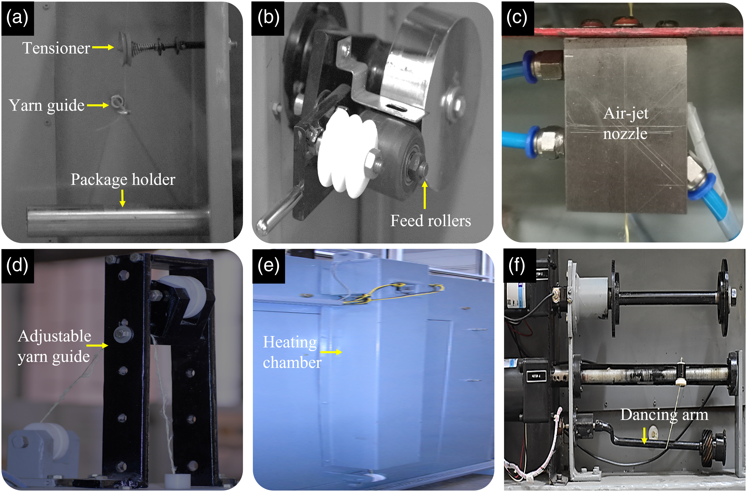
Creeling zone
The machine consists of a creel section, in which two horizontal steel bars are provided to mount the lightweight, small-size yarn supply packages, as shown in Figure 2(a). The large size heavyweight packages can be placed on the floor. When smaller packages are employed, the steel bars hold the feed packages horizontally and easily unwind the reinforcement and matrix-forming filaments. In bigger packages, the yarn is released vertically to the feed zone. Two sets of yarns, namely, reinforcement yarn and matrix yarn, are unwound due to the drag force received from feed rollers and then passed through an eye of yarn guides and to the feeding zone.
Feeding zone
The feeding zone consists of two pairs of feeding assemblies for reinforcement yarns and matrix-forming yarns, as shown in Figure 2(b). Each assembly consists of a pair of rollers, out of which one has a larger diameter of 12 cm and the other has a smaller diameter of 5 cm. The larger diameter roller gets the positive drive from the motor. The small-diameter roller has a rubber coating and rotates due to the frictional contact with the larger roller. Both sets of yarns are made to pass between the nip of these rollers. A spring helps to apply and maintain a constant rate of grip between these rollers. Since individual motors drive these assemblies, feed rollers can feed both yarns at different feeding rates and thus offer different overfeeds. The matrix and filament yarns from the creeling zone are dragged by the feed rollers and a pre-requisite length of yarns are delivered to the subsequent commingling action.
Commingling zone
The reinforcing and matrix-forming filaments from the feed zone are then subjected to the commingling zone. The zone consists of an air jet nozzle, the heart of the commingling machine. The vortex and turbulence formed inside the nozzle facilitate blending these two types of filaments. The nozzle configuration is critical in determining the commingling process efficiency and producing quality towpregs. The nozzle design mainly affects the cyclic production of nip and open sections in the yarn structure. 23 The optimized, cost-effective nozzle configuration capable of working at lower pressure reported by Jogur et al. 3 (shown in Figures 1(a) and 2(c)) is used in the present studies. 3
Adjustable yarn guide assembly, heating chamber and winding zone
After the commingling, the towpregs passes through a small circular yarn guide, adjustable yarn guide, and heating chamber. Slackness in the hybrid yarn is observed above the nozzle outlet while producing the yarn. Yarn slackness occurs due to the increased delivery speed, overfeeding and low air pressure usage. The amount of slackness varies according to the processing parameters used; hence, an adjustable guide bar is essential. The distance between the nozzle outlet and the yarn guide can be adjusted according to the magnitude of yarn slackness. As seen in Figure 2(d), the adjustable guide assembly consists of multiple slots to facilitate the height adjustment. The position of the yarn guide can be raised or lowered depending upon the yarn slackness and the processing parameter used.
A heating chamber (Figure 2(e)) is provided at the machine’s backside, consisting of three heating bars running along the chamber length. The temperature inside the chamber can be adjusted up to 400°C to cover the melting temperature range of many polymer matrices. The heating chamber is introduced to enhance the stability of the towpregs structure by a partial fusing of the polymer matrix. The towpregs are subjected to a temperature above the
A winding unit connected to a separate motor is provided at the front side of the machine to wind the produced COM towpregs on the final package, shown in Figure 2(f). The traversing mechanism is achieved using a 0.5 mm pitch screw bar connected to a separate motor. The traversing movement is obtained using micro-switches on both sides of the final package. A 10 m/min delivery speed is possible with a yarn tension control mechanism. A dancing arm operated by a rotary potentiometer is employed to regulate the yarn tension. As the diameter of the final package increases, the tension on the towpregs also increases. Eventually, the position of the dancing arm also changes according to the increment in package diameter. As a result, a change in voltage signal is experienced by the potentiometer. This change in voltage signal reduces the winding roller speed accordingly and regulates the uniform towpregs tension throughout the process. A control panel helps to adjust and change the process parameters such as feed rollers speed, winding roller speed, traversing speed, and the temperature inside the heating chamber. Separate switches to turn the machine on/off and emergency stops are also included in the control panel.
Box-Behnken design optimization
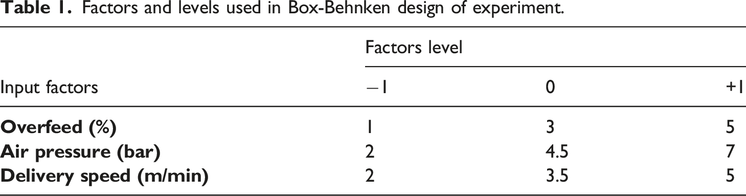
Factors and levels used in Box-Behnken design of experiment.
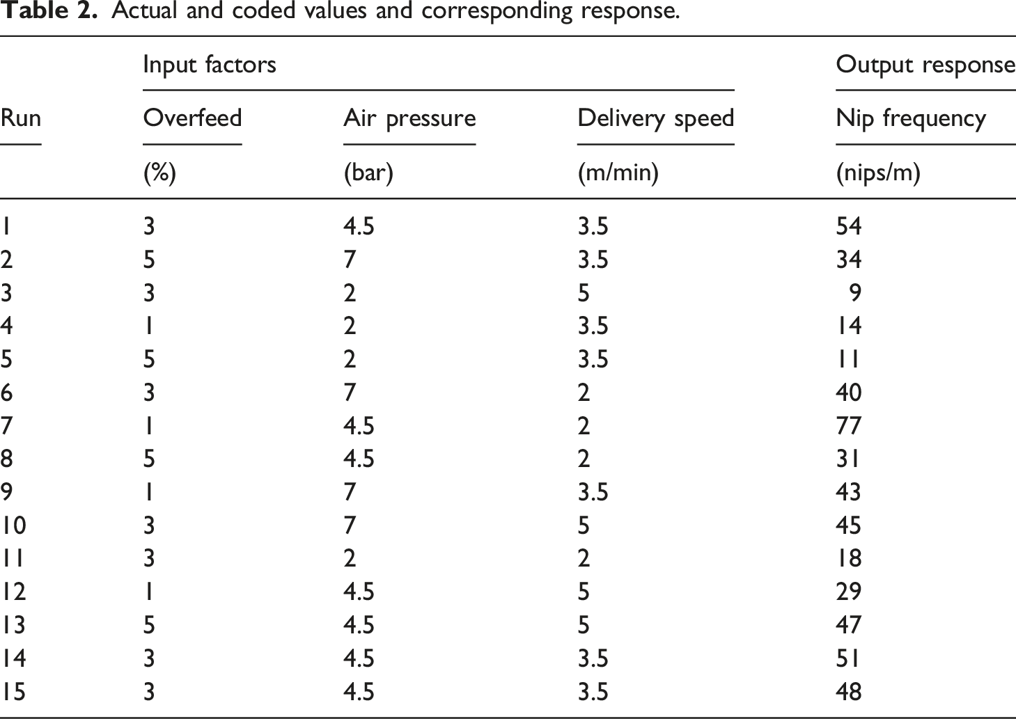
Actual and coded values and corresponding response.
Commingled towpregs production
The COM towpregs for the Box-Behnken optimization study are manufactured using an in-house designed and custom fabricated commingling machine, as shown in Figure 3(a). The schematic of the commingling process is illustrated in Figure 3(b). Fifteen COM towpregs are manufactured at the process parameters mentioned in Table 2 using Kevlar® 29 fibre as a reinforcement and PP fibres as a matrix-forming material. The Kevlar® 29 roving has a linear density of 1.5 denier per filament with 1000 filaments. The PP filament has 120 filaments with a linear density of 7 denier per filament. The diameters of the single filament of Kevlar® 29 and PP are 12 μm and 33 μm, respectively. (a) In-house fabricated commingling machine and (b) schematic of commingling process.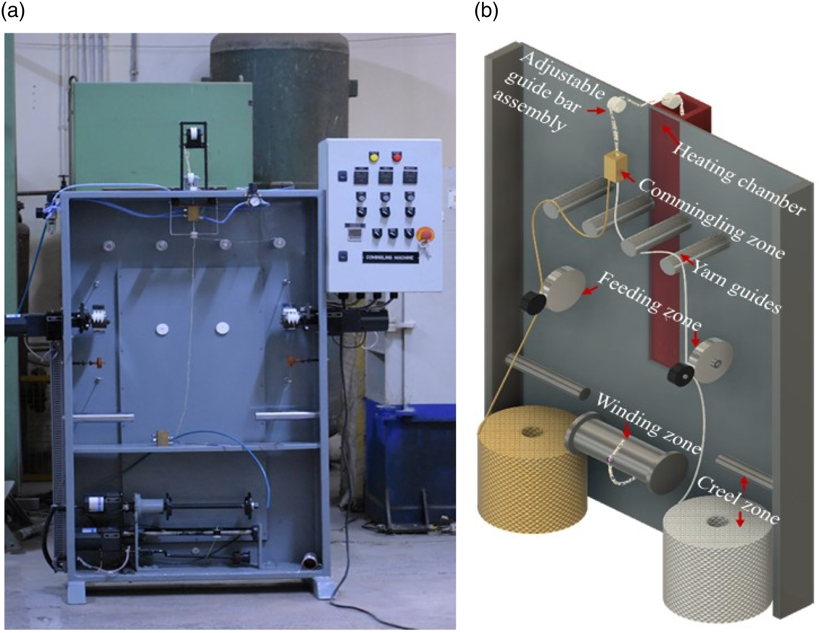
Materials characterization
Characterization of COM towpregs
Nip frequency
The nip frequency (number of nips per meter) in the COM towpregs is determined by counting the nips under the optical microscope. Ten specimens of 1 m length are taken from different parts of the packages to cover all the possible variations in the resultant towpregs.
Nip stability
Instron 3365 UTM instrument is used to conduct the cyclic tensile test to determine the nip stability of the towpregs. The specimens are subjected to loading and unloading force from 0 to 5% strain limit for ten cycles. From the load-elongation curve, the difference between the work done in the first (
Weavability test
Textile pre-forming ability of the towpregs during weaving is investigated using Reutlinger web tester, made by Sulzer Ruti, Switzerland, shown in Figure 4. The instrument simulates all major stresses that occur during weaving, such as cyclic extension, axial abrasion, flexing and bending, but excluding beat-up and yarn entanglements.
25
Five specimens of 50 cm length are gripped between fixed and movable jaw. A yarn abrader positioned between these jaws makes to and from movement at a fixed distance. Towpregs are subjected to 1000 abrasion cycles at the cyclic extension of 0.5% and cyclic fatigue speed of 250 cycles/min. The difference in the towpregs structure before and after the test is analyzed using an optical microscope. Weavability test for commingled (COM) towpregs using Reutlinger web tester.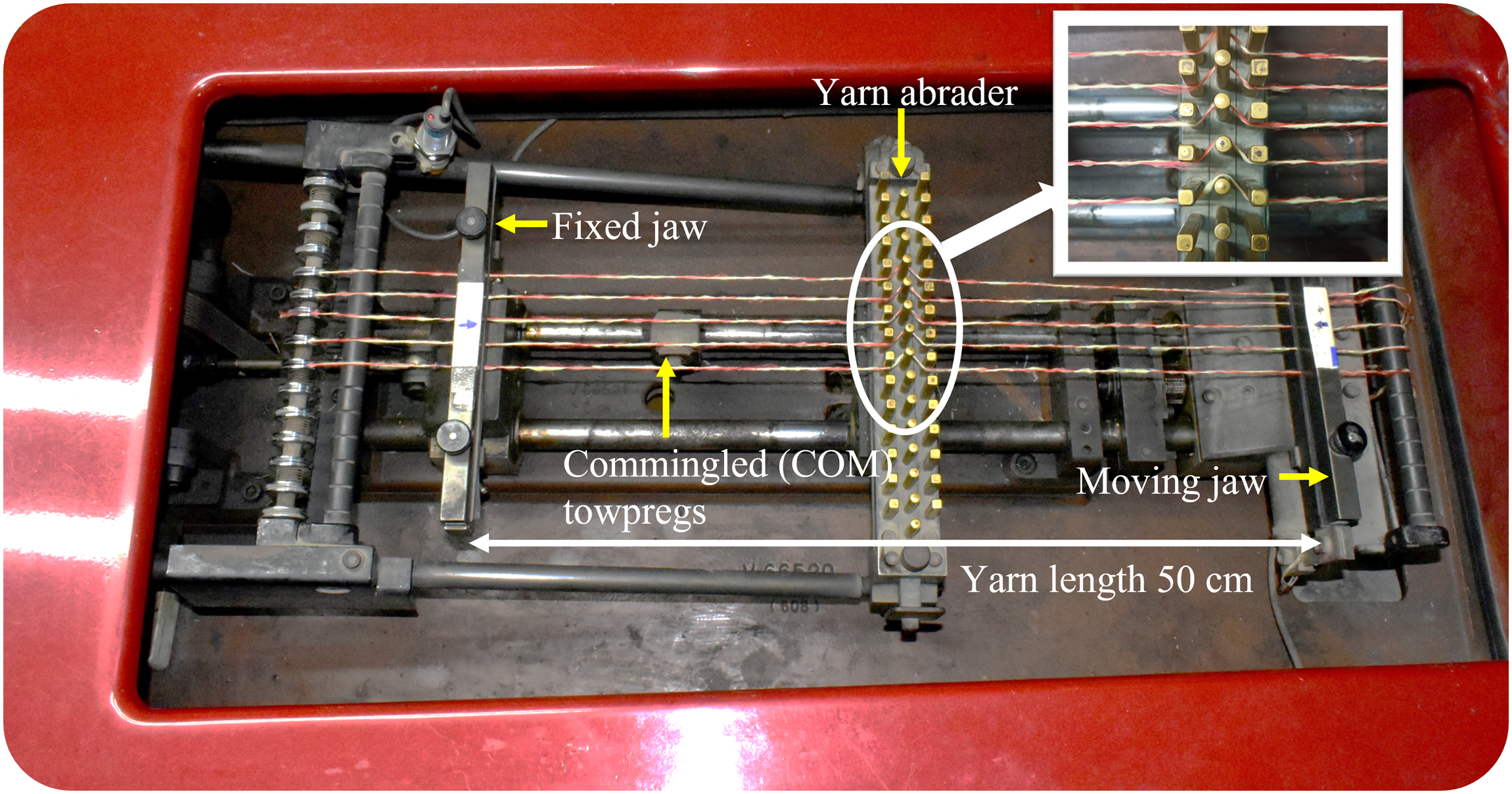
Towpregs microstructure analysis
The migration of Kevlar® and PP filaments in the towpregs cross-section and longitudinal direction are analyzed using optical microscopic images. The yarn analysis is done for the specimens produced at different AP while keeping OF and DS constant.
Flexural rigidity test for towpregs
The flexural rigidities of COM towpregs and parent yarns are determined using a “Shirley weighted ring yarn stiffness tester”. During the test, a ring of towpregs is formed on a cylindrical former of circumference 7.75 cm and gripped at its highest point in a spring clamp. The former cylinder is taken out while allowing the ring towpregs to hang vertically in front of a mirror scale. The scale reading of the lowest point of the ring (R1) is taken, and then the ring is suspended with a hooked weight (m). After 5 seconds new reading of scale (R2) is taken. The deflection (d) value is calculated using equation (2).
The deflection ratio is the ratio of deflection (d) in cm to the ring’s circumference (L) in cm. The Z value is referred from the table provided by the Shirley Institute. The flexural rigidity (G) of towpregs in 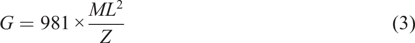
Characterization of UD composites
Void content
The void is critical in determining the consolidation quality and composite properties. A composite with a lower void (%) offers better mechanical and impact performances. The final void in the composite is determined by obtaining the theoretical and experimental densities of the sample.
26
The final void in the composite is determined using equation (4). The experimental density is obtained through the density column method using ethanol as per ASTM-D 317. For theoretical density, firstly, the fibre volume fraction is obtained by dissolving the PP matrix in the liquid xylene at boiling temperature. The theoretical density is then calculated according to the rule of mixture method, using equation (5), as follows.

Flexural strength by three-point bending test
Three-point bending test is performed for UD Kevlar®/PP towpregs composites as per ASTM D7264/D7264M – 21.
27
The transverse flexural strength of the composite mainly depends on the consolidation quality of the composites. This test indicates how well the resin matrix is dispersed within and outside the fibre bundle. Unlike the tensile strength test, which is fibre dominating property, the flexural strength is dominated mainly by the matrix system.
26
A total of five composite specimens with a thickness of 2.7 ± 0.1 mm and span length of 100 mm are flexed at a cross head velocity of 2 mm/min using a universal testing machine (T-72052, DAK Systems, Mumbai, India) equipped with 5kN load cell. The flexural strength (MPa) and modulus (GPa) are determined using equations (6) and (7), respectively.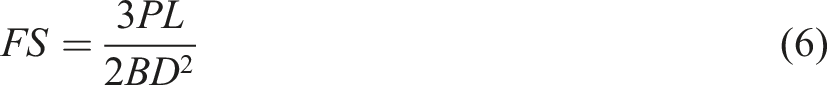
Fabrication of Kevlar®/PP thermoplastic UD composites
The optimized Kevlar®/PP towpregs having a 50/50 fibre to matrix volume ratio are developed and then compressed under optimum moulding parameters. The towpregs are wrapped on a metallic frame having dimensions 300 mm×200 mm. Sixteen towpregs layers are wound from left to right at the middle of the frame and then reversed (right to left) with the same number. The laying sequence is repeated three times to lay 192 towpregs layers. The towpregs bundle is then wrapped tightly with a PP multifilament to fit the bundle within the cavity of the moulds developed. The developed mould has the dimension of 250 mm in length and 13 mm in width. The UD mould is transferred between the pre-heated top and bottom heavy moulds. The towpregs bundle is first pre-heated for 10 min at 200°C without any pressure inside the cavity, later cured at 20, 40 and 60 bar pressure for 5, 5, and 10 min, respectively. The pre-heating of the bundle at zero tension ensures the smooth flow of resin, thus helping to achieve better consolidation quality. The pre-heated bundle is then subjected to 3 breathing cycles at 20 bar pressure to remove any air bubbles entrapped. Subsequently, the bundle is compressed under vacuum at 200°C with a gradual increase in the pressure from 20 to 60 bar. The gradual increment in pressure further penetrates resin within the towpregs bundle. In the final curing, the towpregs bundle is compressed at 60 bar pressure for 10 min to achieve a composite thickness of 2.7 ± 0.1 mm. The moulds are then water-cooled at approx. 9–10°C per min till the temperature drops to 50°C. The fabricated composites have a fibre to matrix ratio of 50/50 by volume. The dimensions of the final composite are 250 mm (length) ×13 mm (width)
Results and discussion
Effect of nozzle diameters on VM, TKE, TI and RV
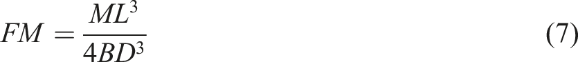
The COM towpregs structure is characterized by the presence of nips/entanglements and open segments across the yarn length. The nips are formed due to the vortex airflow generated within the nozzle. Therefore, the rotation speed of the filaments inside the nozzle increases with the increase in VM (1/s). As a result, the number of nips per unit length in the towpregs also increases. Meanwhile, the random displacement of the filament’s position is only possible at the higher TKE (m2/s2) and TI (%). In addition, a strong RV (m/s) airflow is necessary to strike and open the filament bundles in the balloon shape. Therefore, the fluid parameters VM, TKE, TI and RV have a substantial role in producing quality COM towpregs. Higher the value of these parameters better is the towpregs quality. It is therefore essential to analyze the aerodynamics of the nozzle using these fluid parameters. 3 In the present study, fluid parameters of different diameter nozzles are compared and analyzed to determine the optimum nozzle diameter.
Figures 5(a), (b), (c) illustrate the effect of change in nozzle diameters on the fluid parameters VM, TKE and TI at 7 bar AP. Figure 5(d) depicts the effect of change in nozzle diameters on RV at yarn outlet and inlet planes. It is clear from Figures 5(a), (b), (c) that with the increase in diameter from 5 mm to 9 mm, the values of fluid parameters decrease within the nozzle. The nozzle diameter of 5 mm performs exceptionally in terms of VM, TKE and TI. The fluid parameter values are almost constant between 7 mm to 9 mm diameters. The 3 mm nozzle diameter has a high VM compared to other diameters. However, the TKE and TI values of the 3 mm nozzle are similar to the 7 mm nozzle. Fluid parameters vorticity magnitude (VM) (1/s), turbulence kinetic energy (TKE) (m2/s2), turbulence intensity (TI) (%) and radial velocity (RV) (m/s) at different commingling nozzle diameters at 7 bar air pressure. In Figures 5 (a), (b), (c), the % difference in the values of the fluid parameters between former and later nozzle diameters are given within the parentheses. Similarly, in Figure 5 (d), the % difference in the values of the fluid parameters between the former and later yarn inlets & yarn outlets, in different nozzle diameters are given within the parentheses and square brackets, respectively.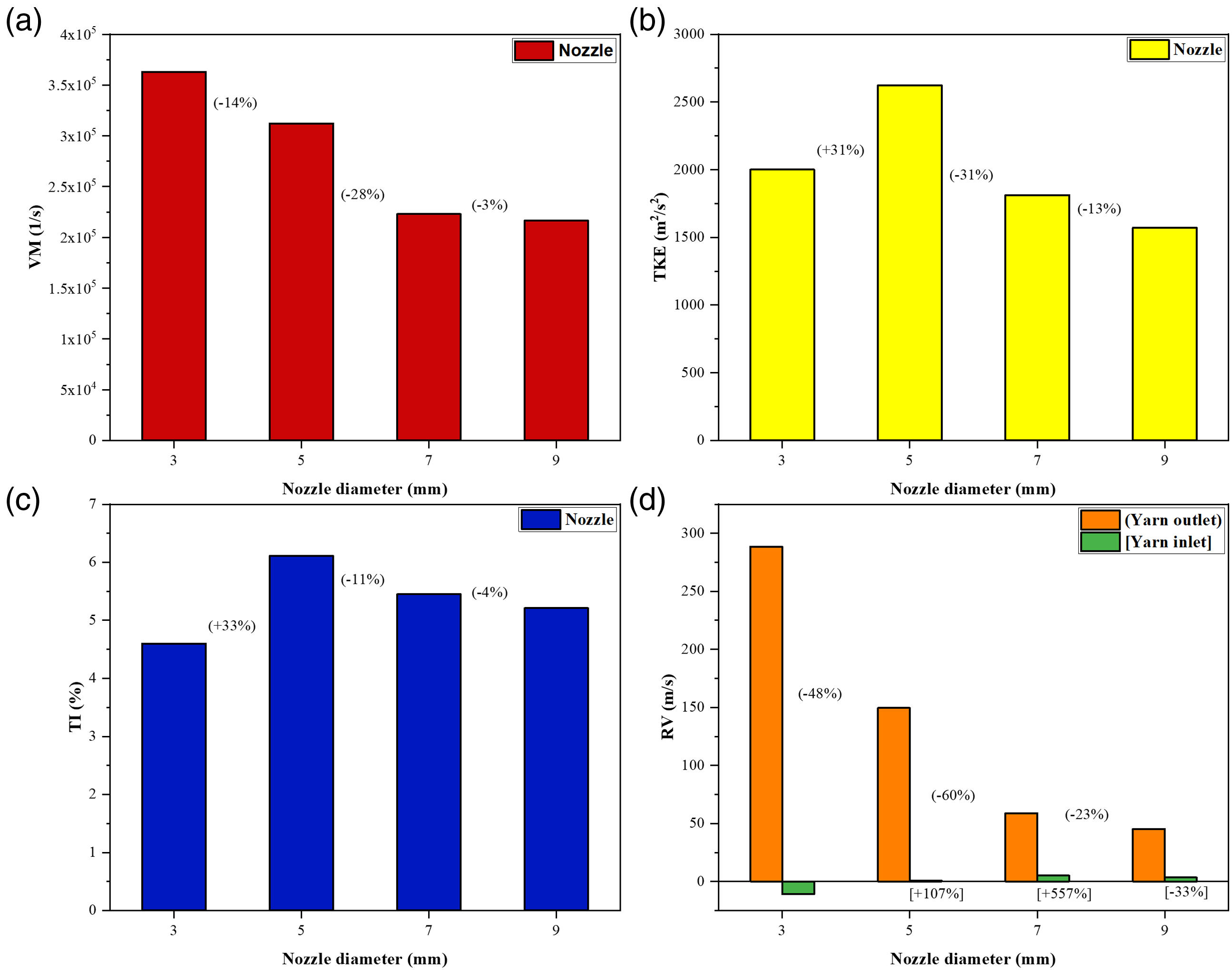
The RV values decrease from 288 m/s to 45 m/s at the yarn outlet planes from 3 mm to 9 mm nozzle diameters. The RV values at the yarn inlet vary between −10.83 to 3.36 m/s from 3 mm to 9 mm nozzle diameters. The magnitude of RV is high at the yarn outlet and too low at the yarn entrance. Variation in RV values between the nozzle diameters at the yarn outlet is ignored due to the non-significant difference in magnitude. The lower RV magnitude at the yarn inlet provides gentle air interaction as the yarn enters the nozzle and thus minimizes the harsh air treatment and fibre surface damage. In contrast, the higher RV magnitude at the yarn outlet provides intense air treatment to the partially mingled bundles, thus increasing the mingling tendency. The results reveal that the nozzle diameters 3, 5, 7 and 9 mm offer powerful vortex and high-intensity turbulent fields within the commingling nozzle. The RV of these nozzles at the yarn outlet plane is also high and beneficial for opening and mixing filaments. The percentage change in the fluid values between 7 mm and 9 mm is insignificant. The same trend is visible and perfectly matches the contour profiles obtained, as shown in Figures 6–8. Vortex distribution in different diameter nozzles. Turbulence distribution in different diameter nozzles. Radial velocity distribution in different diameter nozzles.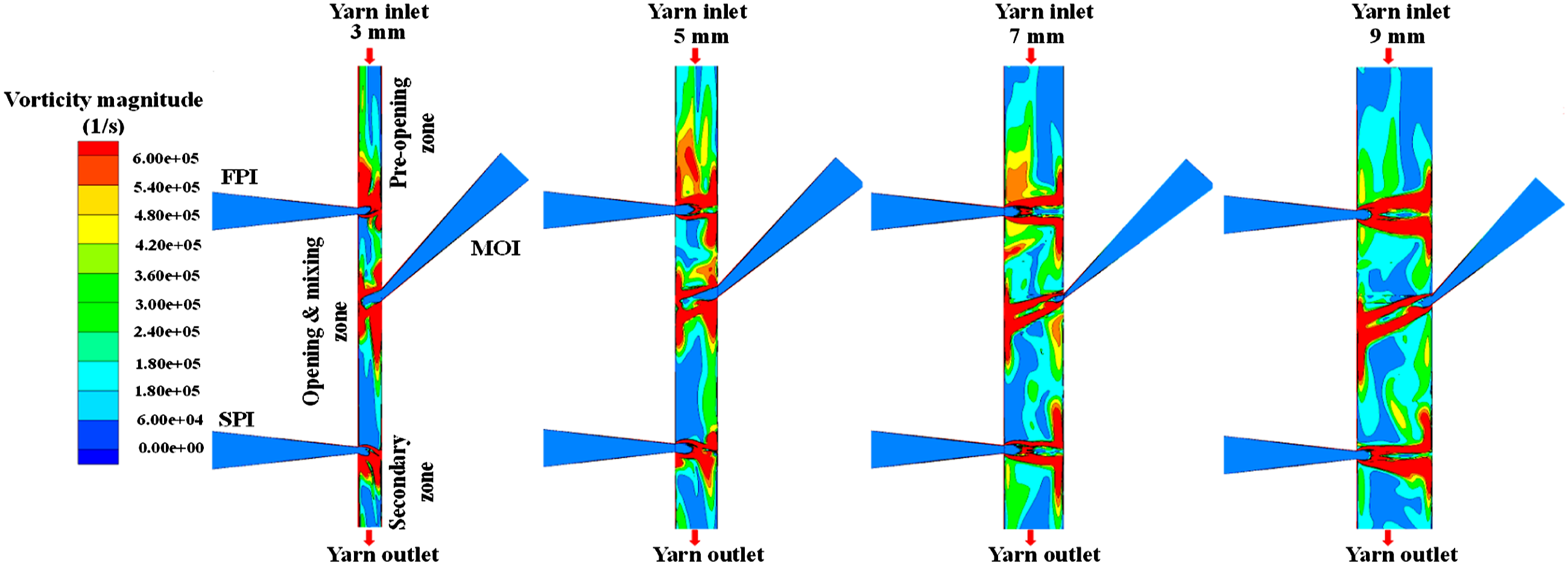
The simulation results reveal that at constant AP (7 bar), the increase in the nozzle diameter decreases the total velocity inside the nozzle, reducing the magnitude of other fluid parameters. The results follow the continuity and Bernoulli’s equation. The velocity within the nozzle is inversely proportional to the area of the nozzle. The magnitude of fluid parameters varies as the total velocity changes. The decreased velocity results in lower kinetic energy and thus reduces the magnitude of fluid parameters within the nozzle. The VM, TKE, TI and RV values drop from 5 to 9 mm nozzle diameter. However, the 3 mm diameter nozzle showed a lower magnitude of fluid parameters due to less area available in the nozzle cross-section.
In practice, the introduction of filament bundles during commingling affects the flow behaviour of the nozzle. Therefore, the investigation is conducted by feeding filament bundles to the nozzles at different AP to understand the effect of filament’s presence inside the nozzle. The optimum nozzle diameter is determined by comparing the nip frequency of the resultant towpregs produced at different AP at different nozzle diameters. The towpregs are produced at identical processing conditions keeping OF and DS constant while varying AP. The OF of Kevlar® and PP is 3% and 1%, respectively. The constant DS of 2 m/min with varied AP (2, 4.5, and 7 bar) are used for producing COM towpregs.
Nip frequency of commingled (COM) towpregs produced at different diameters.
In contrast, the 7 mm nozzle diameter produced exceptional quality towpregs compared to the others. The available empty area for commingling the individual Kevlar® and PP filaments increased to an optimum level at 7 mm nozzle. This increased optimum gap offers better fibre displacement within and between the Kevlar® and PP filament bundles and thus produces highly mingled compact COM towpregs. Due to the increased mingling behaviour of the fibre, the number of nips formed also rose sharply. The NF increased from 23 to 75 at 2 bar and 4.5 bar, respectively, dropping to 44 with the further increase in AP (7 bar).
The 9 mm nozzle showed poor performance with zero nip frequency from 2 to 7 bar. The increased free space seems too high at the 9 mm diameter nozzle. Much filament movement restriction is needed to retain the filament bundles within the potential air-to-fibre interaction area. Otherwise, the air streamlines will push the filament bundles out of the potential interaction zone without causing entanglements. Therefore, the final towpregs would have no nips formed and be a side-by-side hybrid yarn structure.
Effect of process parameters on nip frequency
In the present study, individual parameter AP, interaction parameters OF×DS, and square of parameter AP
2
are highly significant with p-values <0.0001, 0.0002, and <0.0001, respectively. A high correlation coefficient of 
Figure 9(a) depicts the 3D surface plot to highlight the influence of interaction parameters AP and OF on NF at 3.5 m/min delivery speed. It is evident from the figure that OF has an insignificant role in forming nips, while AP has a significant influence. At any constant AP value, the NF decreases with the increased OF value from 1% to 5%. However, the change in NF magnitude is not significant. In the commingling process, yarn OF is either zero or very low. Iemoto et al.
28
found maximum nip frequency at 1% OF. The increased OF of PP from 1% to 5% reduces the yarn tension inside the nozzle. As a result, slack-tensionless PP filaments might move out of the potential air interaction. Eventually, PP filaments fail to interact with Kevlar® filaments, leading to decreased NF. (a) Effect of interaction parameters AP and OF, (b) AP and DS, (c) DS and OF on output response NF . AP: air pressure; OF: overfeed; DS: delivery speed; NF: nip frequency.
On the other hand, the NF increased with the rise in AP value from 2 to 4.5 bar and dropped at 7 bar. The NF of 53 is obtained when AP and OF values are set at 4.5 bar and 1%, respectively, at 3.5 m/min DS. The effect of AP and DS interaction parameters on yarn NF at 3% OF is shown in Figure 9(b). Nips formation is significantly influenced by the parameter AP, while the parameter DS plays an insignificant role. NF of 52 is obtained with AP 4.5 bar and DS 2 m/min at 3% PP OF. At any constant DS value, NF increases with an increase in AP from 2 to 4.5 bar and later drops at 7 bar.
Similarly, NF increases with a decrease in DS at any constant AP value from 5 to 2 m/min. The reduction in DS provides maximum air-yarn interaction time inside the nozzle. As a result, Kevlar® and PP filament bundles are strongly subjected to the potential air interaction, leading to more nips/m. The interaction parameters DS and OF impart a vital role along with AP in forming more stable nips/m. A maximum NF of 77 is observed at 4.5 bar AP with 1% OF and 2 m/min DS, as shown in Figure 9(c). Lower DS (2 m/min) and OF (1%) lead to a higher air-yarn interaction time and a higher probability of nip formation. The individual parameter AP is dominant in forming stable and entangled nips across the towpregs structure.
As the AP increases, the kinetic energy inside the nozzle also increases; thereby, VM, TKE, TI and RV increase. Eventually, increased AP leads to more filaments position displacement, filaments opening and entanglement. However, in the present study, reduction in the filament opening, displacement and nip formation are noticed as the pressure increased from 4.5 bar to 7 bar. At the same time, the NF increased from 2 bar to 4.5 bar. The main reason behind the NF reduction is associated with the nozzle design. The current study utilizes a nozzle design that works on the forward airflow principle, meaning maximum airflow velocity streamlines towards the yarn outlet. The presence of an oblique air inlet at the middle of the nozzle makes this nozzle unique with forwarding airflow. Here, the increase in AP increases the velocity of the oblique inlet. As a result, filament bundles that directly face the air streamlines would be pushed to move towards the yarn outlet. Eventually, filament bundles might not get enough air-interaction time to mingle with each other as the velocity of the oblique air inlet increases.
At the low AP of 2 bar, a small magnitude of outward airflow push (towards yarn outlet) is imparted on the filaments and therefore has more air-yarn interaction time. However, the overall kinetic energy inside the nozzle is not strong enough to displace the position of the individual filaments to a large extent and form more entangled nips. A median AP of 4.5 bar is proven to be significant in creating maximum stable nips. At 4.5 bar pressure, the nozzle has sufficient TKE inside the nozzle to open and displace the position of the filaments. At the same time, the magnitude of outward filaments push is not high enough to cause lower air-yarn interaction. Therefore, maximum NF is observed at 4.5 bar due to the sufficient TKE and air-yarn interaction time present within the nozzle. At a higher AP of 7 bar, filaments are blown out towards the yarn outlet at a higher magnitude and hence, filaments would not spend sufficient time inside the nozzle to form entangled nips. In other words, the filament bundles are pushed out of the potential air interaction zone. Hence, poor filament displacement and opening and reduction in mixing are noticed.
It is inferred from the Box-Behnken design experiment study that COM towpregs with a maximum NF of 77 is produced at processing parameters – OF 1%, AP 4.5 bar, DS 2 m/min. COM towpregs with a higher NF is beneficial as it consists of more filament entanglement and mingling features. For further optimization, three different COM towpregs are produced at 2 bar, 4.5 bar and 7 bar AP with OF at 1% and DS at 2 m/min using the optimized 7 mm diameter nozzle. The produced specimens are subjected to towpregs structure analysis, NF, nip stability, weavability and flexural rigidity tests to arrive at the best quality towpregs and determine the effect of AP on COM towpregs.
Towpregs microstructure analysis
The analysis of COM hybrid yarn structure is essential as it directly affects the towpregs properties, influencing textile pre-forming and consolidation processes. The study provides a clear understanding of the towpregs structural features, namely regularity, compactness, mixing quality and NF. Generally, a compact and regular structure with random mixing of filaments at the towpregs cross-section and longitudinal section is of utmost importance. It is inferred from Figures 10(a) and (b) that the towpregs produced at 4.5 bar have better compactness, high regularity with more NF and excellent mixing quality. In contrast, the towpregs made at 2 bar show bulkiness, irregularity, insignificant NF and poor maxing quality. The quality parameters of the towpregs produced at 7 bar lie between 2 bar and 4.5 bar. These yarns show medium bulkiness, good regularity and medium NF with average mixing quality. (a) Longitudinal and (b) Cross-sectional morphology of COM towpregs structure at different air pressures. [Red colour filaments denote PP and yellow colour filaments denote Kevlar®]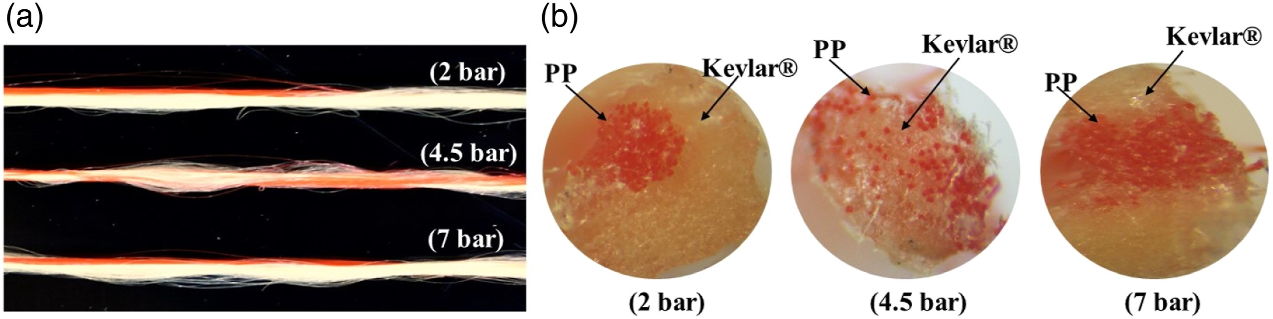
At 2 bar, the kinetic energy required to displace the position of the individual filaments lying inside the nozzle is not sufficient. In other words, the VM, TKE and RV formed inside the nozzle cannot push the filaments out of their original positions. As a result, only a few weak entanglements between the individual filaments of Kevlar® and PP are observed. The increased AP of 4.5 bar and available space led to the higher and random fibre displacement between both filaments. Consequently, at 4.5 bar, a compact and regular COM towpregs structure with a greater NF and fibre mixing quality is observed. At 7 bar, the fluid streamlines push the filaments out of their potential air interaction zone, leading to decreased NF formation, average mixing quality, and medium bulkiness and regularity. The COM towpregs produced at 2 bar and 7 bar are not feasible in textile pre-forming as they might cause significant filamentation problems with frequent yarn breakages and loom stoppages.
Nip stability
The nip stability is an important COM towpregs quality parameter that determines the efficiency of textile pre-forming operations. Textile pre-forming would function smoothly with higher production efficiency if the towpregs have stability in the structure. In the commingling process, the stability of the towpregs structure mainly depends on the strength of the individual entangled nips and the number of nips per meter formed across the longitudinal yarn structure. In the present study, the nip stability per nip is expressed in terms of relative decay (RD). RD indicates the average work done per nip. In other words, the amount of energy a single nip can absorb during cyclic tensile testing. High RD means high energy absorption offered by a single nip. Therefore, the towpregs having many nips with relatively high RD denote high structural stability.
The decay % indicates the magnitude of energy spent removing the full nips or entanglements in the yarn structure. In other words, the total resistance offered by the entrapped filaments and full nips between the first and tenth loading cycle is expressed in terms of decay %. Therefore, high decay % is also an indication of increased mixing and entrapment of filaments. The decay % value of each COM towpregs is divided by the NF to determine the RD, which indicates the energy absorbed by each nip in the yarn structure. 3 The current study shows that the yarns formed at 2 bar have RD of 1.34 with decay % of 30.94 and NF of 23. RD of 0.72 is noticed at decay % 54.19 and NF 75 for the yarns produced at 4.5 bar. The yarns of 7 bar have RD of 0.82 with decay % of 36.36 and NF of 44.
Stability of towpregs produced at different air pressures.
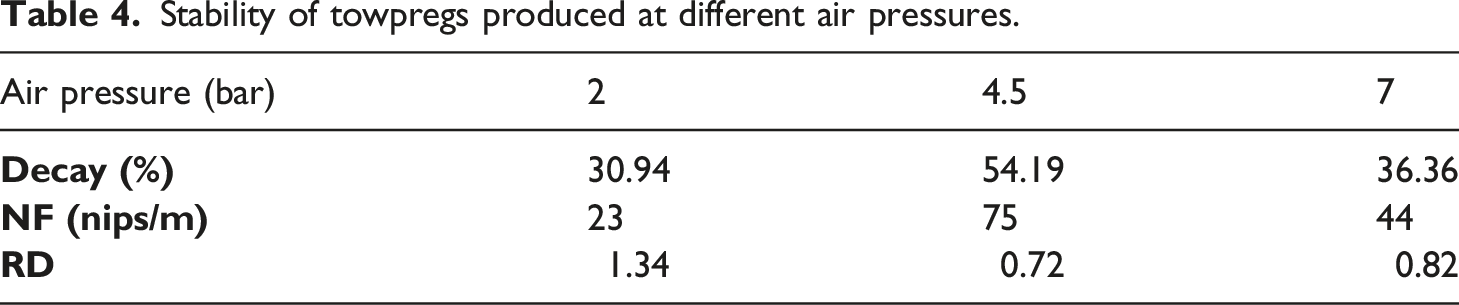
In contrast, the towpregs with low decay % and less NF have mostly filaments lying straight in the yarn axis and barely show any filaments mixing and interlocking. Such towpregs are not desirable in textile pre-forming as they cause filamentation and poor fibre-matrix impregnation during the consolidation process. In conclusion, the towpregs having high RD with high NF show better stability across the yarn structure, while poor yarn stability is demonstrated by the towpregs formed with low RD and poor NF.
Weavability test
The COM towpregs manufactured at different AP are subjected to the weavability test. These towpregs are subjected to intense stress conditions to simulate the pre-forming effect. The towpregs passing this harsh weaving condition can be easily woven into pre-forms. The weavability is determined by analyzing microscopic images of towpregs before and after the test for filamentation, nip stability and fibre damage, shown in Figure 11. The weavability of COM towpregs significantly relies on the stability of towpregs structure, which in turn depends on the yarn structural features such as NF and nip stability. Generally, the stability of the towpregs structure enhances as the entrapment strength (filaments interlocking strength) between the individual filaments increases. A towpregs with high RD per nip and high NF provides a stronger interlocking of filaments. It offers excellent resistance to abrasion, stress and strains that occur during the weaving process. A stable towpregs structure maintains the complete nip structure and does not readily undergo filamentation and fibre damage under weaving conditions. Using such stable towpregs structure not only increases the weaving performance but also minimizes the resin melt flow distance and offers excellent matrix impregnation during the consolidation.
3
Microscopic images captured before and after the weavability test at 2, 4.5 and 7 bar. (a),(b),(c) show towpregs morphology before the test and (a!), (b!), (c!) show microscopic images captured after weavability test. [Red colour filaments denote PP and yellow colour filaments denote Kevlar®]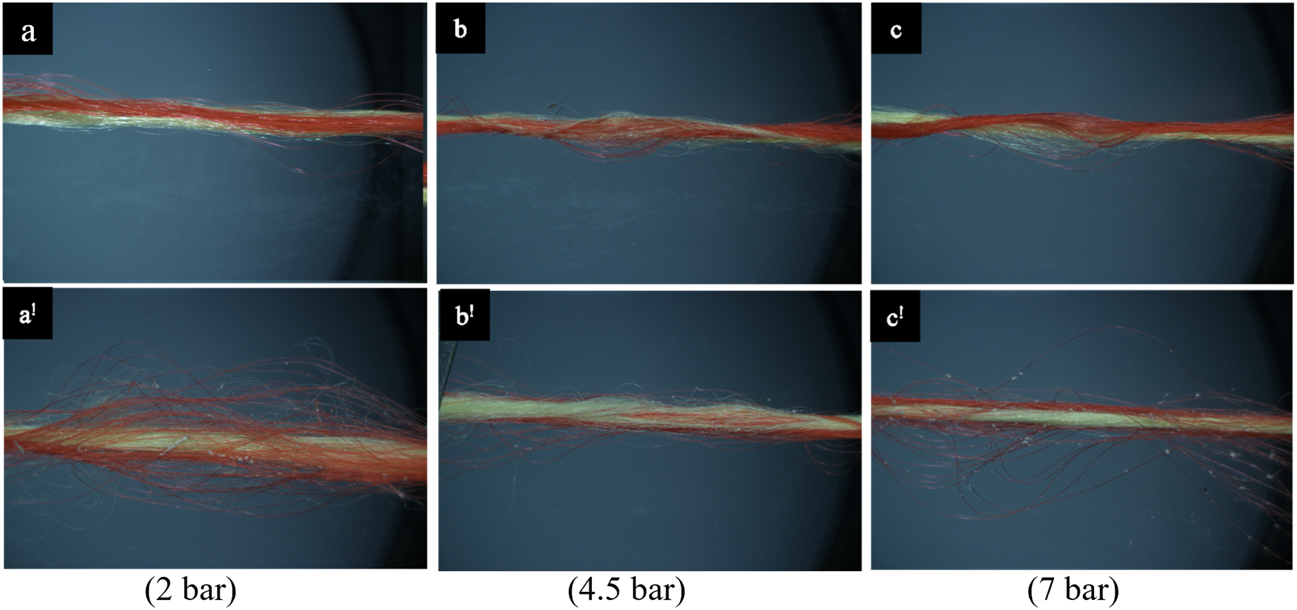
It is observed that the towpregs formed at 4.5 bar show the highest weavability performance, followed by the towpregs produced at 7 bar and 2 bar. The towpregs formed at 4.5 bar have the highest yarn stability due to good RD (0.83) and the highest NF (75). Therefore, negligible filamentation with no fibre surface damage is observed in this case. These towpregs show a stable nip structure even after the wevability test. These towpregs have a strong interlocking of filaments along the length, showing excellent weavability. The COM towpregs produced at 2 bar and 7 bar showed maximum filamentation with some fibre surface damage. The nips underwent disentanglement during the weavability test in both the towpregs. The towpregs formed at 7 bar still show some structural integrity, while poor structural stability is seen with hybrid yarns made at 2 bar.
Flexural rigidity of towpregs
The towpregs flexural rigidity is affected by the arrangement and interaction behaviour between constituent fibres, yarn geometry, and their mechanical properties. 29 The fibre parameters (dimension, stiffness, clustering) and yarn parameters (torsional rigidity, linear density, diameter and twist) influence the overall towpregs flexural rigidity. The COM towpregs are nothing but blended yarns, which are more complex than the individual parent yarns. This complexity of blended towpregs restricts the freedom of fibre motion at different locations of the yarn bundles at varying extents. 30
Flexural rigidity of COM towpregs at different air pressure.
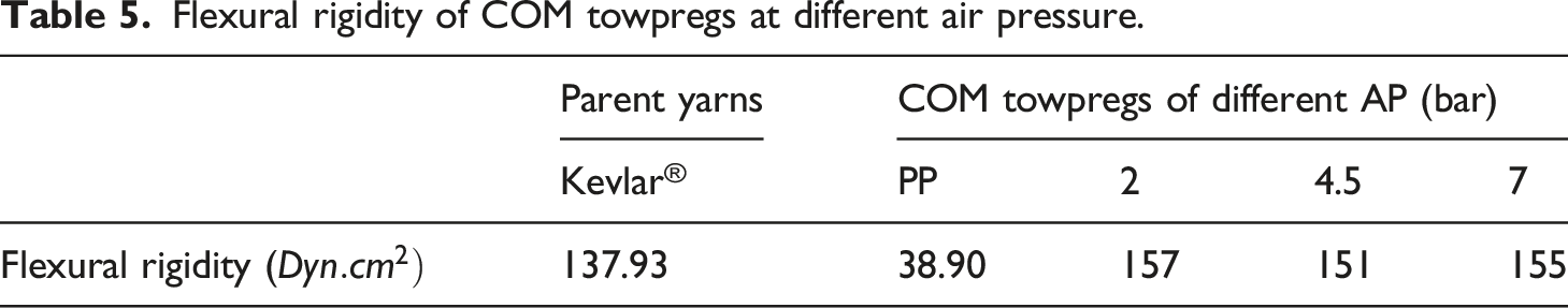
The towpregs with high flexural rigidity (as in powder coated and melt coated) create many difficulties during textile pre-forming. These rigid towpregs may break due to high abrasion and bending movements associated with textile pre-forming, causing frequent machine stoppages. In addition, polymeric resin might slip off from the fibre bundle or de-mingle, leading to poor impregnation in the consolidation process. To avoid such problems, towpregs with low flexural rigidity are preferred.31,32 In this aspect, COM towpregs offer great flexibility compared to other towpregs and thus eliminate the difficulties of textile pre-forming. 33
Void in UD composites
The UD Kevlar®/PP composites made through COM towpregs showed a minimum void of 4.3%. The scanning electron microscope (SEM) micrographs of the cut cross-sections of UD Kevlar®/PP composite taken at different magnifications are shown in Figure 12. The SEM images hardly show any void in the UD composites. However, resin-rich regions (encircled areas) can be seen in some places. It is understood from the SEM micrographs that both fibre and matrix are indistinguishable, meaning better impregnation quality is achieved. The lower void percentage with indistinguishable fibre and matrix region leads to better load transfer. However, the matrix-rich region (encircled area) might act as a weak link leading to the early failure of composites. SEM micrographs for the cut cross-section of UD Kevlar®/PP COM composites at (a) lower magnification and (b) higher magnification. (Encircled/highlighted area represents matrix rich region).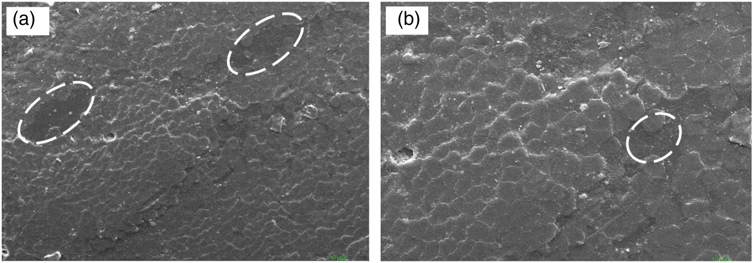
Flexural strength of UD composites
Major failure modes observed in the specimens tested for flexural strength are the compressive and tensile failure modes, seen at the top and bottom of the specimen, respectively. In general, UD composites with fibres oriented in the span direction (0°) shows the domination of compressive failure as the compressive strength is typically lower than the tensile strength.
26
The same trend can be seen in Figure 13. The fibre buckling/kinking at the compression side of the specimen and mass accumulation of fibres without breakages at the tension side of the specimen are the dominating failure modes observed in the UD Kevlar®/PP composites. Microscopic view of (a) compression and (b) tensile failure sides of the UD Kevlar®/PP COM composites.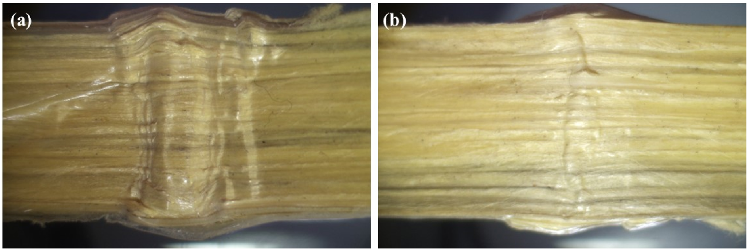
The load-extension curve for UD Kevlar®/PP composites is shown in Figure 14. The onset fracture in the composite can be seen at 2.89 mm extension, indicating initiation of fibre matrix de-bonding. The fracture propagates with a further increase in the loading, and finally, the specimen fails sharply at 4.91 mm extension with a maximum peak load of 113 N. Unlike thermoset Kevlar® composites which fail catastrophically (brittle failure), the thermoplastic composites exhibit plastic failure due to the visco-elastic behaviour of PP resin and flexible behaviour of Kevlar® fibres. The developed UD Kevlar®/PP composites show the shoulder region due to the plastic deformation caused by the matrix. The PP matrix can still deform even after the peak load, thus avoiding catastrophic failure. This behaviour can be attributed to better fibre-matrix dispersion meaning good consolidation.
34
The developed UD composites exhibit average flexural strength of 130 MPa and flexural modulus of 28 GPa. Load-Extension curve for UD Kevlar®/PP COM composites under three-point bending test.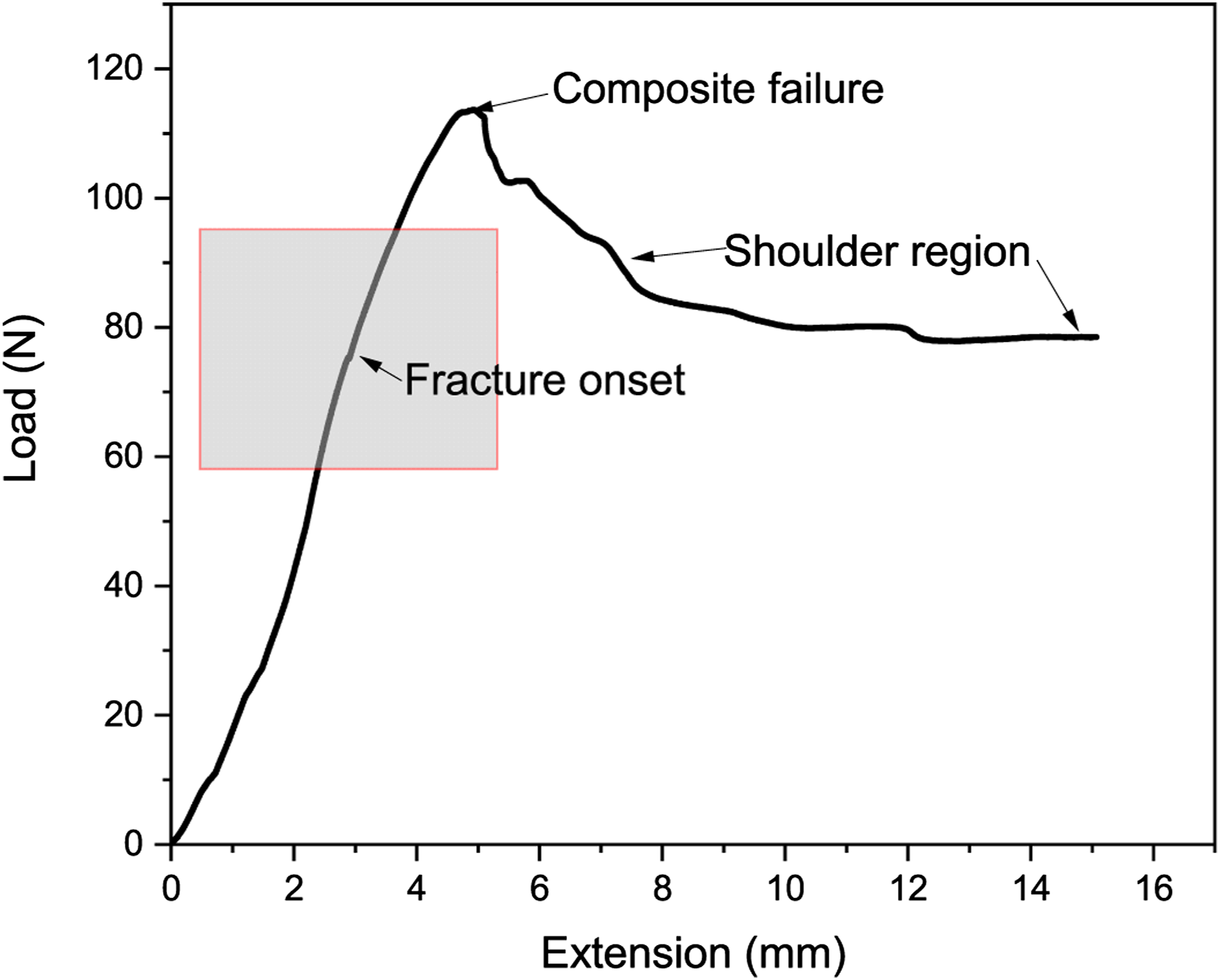
Conclusion
The current study focuses on developing optimized COM towpregs based UD Kevlar®/PP composites by optimizing commingling nozzle diameter and processing parameters using computational simulation and experimental methods. The study investigates the features of COM towpregs developed and analyses the consolidation quality and flexural properties of the developed UD Kevlar®/PP COM composites. The effect of commingling process parameters on the quality of towpregs is also investigated.
The study concludes that the 7 mm nozzle diameter forms ideal COM hybrid yarns/towpregs for thermoplastic composites. The nozzle showed excellent VM, TKE, TI and RV values and offered optimum free space for filament mingling inside the yarn channel. Therefore, flexible COM towpregs with the high NF, nip stability, weavability, regularity, compactness and mixing quality are produced using an optimized 7 mm nozzle diameter with processing conditions - AP of 4.5 bar, DS of 2 m/min OF of 1% for PP and 3% for Kevlar®. The parameter AP significantly influences the formation of stable nips. The interaction parameters OF and DS should be as minimum as possible to facilitate maximum air-filament interaction. The towpregs produced by the 7 mm diameter nozzle at the aforementioned optimum processing conditions make the textile pre-forming effortless with minimum fibre damage and loom stoppages.
The UD Kevlar®/PP COM composites formed with optimized towpregs offered excellent transverse flexural properties due to the enhanced impregnation quality. The lower void of 4.3% represents better fibre-matrix impregnation quality achieved due to the homogeneous mixing of fibre and matrix filaments along the length and cross-sections of the towpregs. SEM micrographs also depict quality consolidation with good matrix dispersion between the reinforcing fibres. As a result, the lowest melt flow distance during consolidation is achieved, leading to improved flexural properties. The UD composites exhibit average flexural strength of 130 MPa and flexural modulus of 28 GPa. In future studies, mechanical and impact performances of UD, 2D and 3D composites made through optimized COM towpregs will be studied.
Supplemental Material
Supplemental material - Development of Kevlar®/polypropylene towpregs through optimized commingling nozzle and processing parameters for thermoplastic composites
Supplemental material for Development of Kevlar®/polypropylene towpregs through optimized commingling nozzle and processing parameters for thermoplastic composites by Ganesh Jogur, Apurba Das and R Alagirusamy in Journal of Thermoplastic Composite Materials
Footnotes
Declaration of conflicting interests
The author(s) declared no potential conflicts of interest with respect to the research, authorship, and/or publication of this article.
Funding
The author(s) disclosed receipt of the following financial support for the research, authorship, and/or publication of this article: This work was supported by the Directorate of Extramural Research & Intellectual Property Rights (ER & IPR) Defense Research & Development Organization (DRDO) (ERIP/ER/1300464/M/01/1633).
Supplemental Material
Supplemental material for this article is available online.
References
Supplementary Material
Please find the following supplemental material available below.
For Open Access articles published under a Creative Commons License, all supplemental material carries the same license as the article it is associated with.
For non-Open Access articles published, all supplemental material carries a non-exclusive license, and permission requests for re-use of supplemental material or any part of supplemental material shall be sent directly to the copyright owner as specified in the copyright notice associated with the article.