
Abstract
It is essential to investigate the nonlinear phenomena associated with rolling ships to enhance marine operations, reliability, and stability under challenging circumstances. Ship design, operating protocols, and control strategies are improved by comprehending and anticipating these patterns of behavior. A dynamic analysis of the nonlinear rolling ship model under a parametric force is presented in this work. The nonlinear derivative feedback (NDF) control is used to enhance stability and lessen unwanted vibrations, particularly in the resonance zone. To obtain the approximate solutions (AS), the multiple-scales process (MSP) develops and solves the differential formula regarding the nonlinear rolling ship to the proper order. The correctness of the AS is verified by comparing it to the calculated numerical solutions (NS) using the fourth-order Runge–Kutta process (RK-4). Solvability requirements and resonance examples are explored to acquire the modulation formulas. MATLAB programming is used to display the frequency responses and time histories of the obtained solutions graphically. Furthermore, the temporal histories of the obtained solutions are analyzed graphically both with and without control. Stability analysis and steady-state results are also investigated using resonance curves. To determine the crucial factors that result in significant fluctuations in the structure’s behavior, the nonlinear dynamics of the model are further examined using bifurcation analysis, as represented by bifurcation diagrams. Periodic as well as chaotic oscillations are studied using the Poincaré diagram, which sheds light on the long-term equilibrium of the structure and the genesis of chaotic processes. These findings facilitate a better understanding and mitigation of dynamic disruptions in flexible structures across diverse operating environments. The dynamical analysis of the rolling ship model plays a vital role in enhancing ship stability, safety, and performance. It aids in the design of anti-roll systems, ensures cargo security, and informs safe operational guidelines under varying sea conditions. Additionally, it supports simulation-based crew training and helps predict critical transitions to chaotic motion, reducing the risk of capsizing and improving overall maritime safety.
Keywords
Introduction
The rolling motion of a ship refers to its oscillatory rotation about the longitudinal axis due to external disturbances such as ocean waves. This motion is inherently nonlinear, influenced by factors like hull geometry, damping, and restoring moments resulting from buoyancy and gravity. Understanding the dynamics of ship roll motion is crucial for stability analysis, control strategies, and optimizing ship design to mitigate excessive rolling and ensure safe navigation.1–3 Recent studies extend traditional ship stability analysis by considering dynamic instabilities in waves. Numerical simulations were employed to investigate transient roll responses to sudden heeling, with a focus on wave effects, damping, and nonlinear restoring forces, in order to identify potential instability. 4 Moreover, 5 derived kinematic models to unify maneuvering and seakeeping analyses using a robotics-based matrix approach, enabling the transformation of seakeeping equations into body-fixed coordinates. Furthermore, efficient computational models for real-time ship motion simulation were presented, accommodating various ship types, engines, and sea conditions. A simulation system was developed for educational and entertainment purposes, allowing users to interactively adjust ship and environmental parameters. The models, based on Newtonian mechanics, capture six degrees of freedom, ensuring high-fidelity motion simulations. 6 The authors in 7 studied the significant impact of ship rolling on the marine gear transmission system, highlighting increased vibrations, quasi-periodic and chaotic behavior, and a 23.81% rise in response amplitudes. By incorporating rolling effects into the marine gear transmission model, the research provides critical insights for optimizing marine transmission systems and navigation strategies to enhance stability and performance. On the other hand, the work of 8 explored the potential of harvesting wave-induced energy on ships using linear generators. Results show that while insufficient for propulsion, the generated power (1–2 kW per ton) could supplement auxiliary systems, offering a practical marine energy solution.
In the engineering curriculum, vibration control is crucial for minimizing negative impacts. A modified integral resonant control method was employed by 9 to enhance the bandwidth of a weakly damped resonant structure. Subsequently, a method for reducing the controller’s directive via a selected input by choice was created, which deviated from the conventional approach of this controller. Additionally, controller settings have been theoretically established to offer the maximum detection bandwidth. The periodic solution of the nonlinear oscillator, which describes the extended Rayleigh formula, was examined by. 10 Two distinct time delays−one for location and one for proportional velocity—were employed to regulate the vibration of the Van der Pol-Duffing-Rayleigh oscillator. The authors in 11 assessed the immediate standard using the method of harmonic balance and MSP. Regarding the study of the unforced and undamped Duffing oscillator, it has been demonstrated that these techniques provide sufficient precision for analyzing backbone shapes when the amplitude fluctuation is modest. To control the bifurcation occurring in a fractional predator-prey mechanism, 12 employed delayed feeding. In, 13 an investigation of the dynamically stable and unstable performance of a set of linked van der pol oscillators was performed. Additionally, it is analytically stated that the oscillator’s amplitude grows if the stability conditions are not met.
To increase the stability of the one-degree-of-freedom giant magnetostrictive actuator apparatus and manage its irregular vibratory properties, such as its principal frequency response, chaotic position, and regulating phase intensity, a feedback algorithm for displacement as well as velocity involving a time lag is devised in. 14 Giant magnetostrictive materials have gained widespread applications in various fields, including electro-hydraulic servo valves, aircraft, and gasoline infusion systems operated under electrically controlled conditions.15–20 The researchers in 21 developed a regressive variable differential equation for a cable-stayed beam, regulated through time-delayed responses. The outcomes showed that displacement or acceleration feedback regulation outperformed velocity input control. In, 22 a longitudinal vibration structure for an electromechanical link transmission mechanism was created. The zone of disturbance shrank as the feedback gain rose, causing the motion to change from chaotic to periodic.
In, 23 the MSP was utilized to mitigate unwanted residual harmonics in both conventional and unconventional Duffing systems, employing a two-scale feed-forward control technique. One basic method is the linear negative displacement feedback control system, in which the regulating force acts directly against the displacement.24,25 This controller exhibits special stability properties in time-delayed situations, particularly when controlling various types of vibration.26,27 In, 28 the transversal time-delay loop control strategy was used to mitigate sub-harmonic and super-harmonic oscillations in a suspended cable. The Galerkin procedure was employed to derive the nonlinear differential equations of the planner motion, which were then transformed into delayed differential equations. Although time delay in the loop of feedback may decrease the efficacy of velocity feedback (VFB), investigations have demonstrated that it still performs well, regardless of various contextual circumstances. 29 The intrinsic nonlinearities in cable structures are addressed by the adverse cubic VFB controller. 30 Liu et al. 31 investigated the nonlinear oscillation characteristics of micro-nano-harmonic oscillators combined with delay time VFB, applying the multi-scale technique to determine the critical parameters for the chaotic motion of the structure.
The micro-oscillator subsystem’s chaotic motion was recorded by Bassinello et al., 32 who also examined the effects associated with each influencing factor and effectively managed the chaotic oscillation of the entire apparatus. Shang and Wen 33 examined a micro-electromechanical system resonator with delayed feedback regarding position. It was shown that using delayed control via feedback efficiently suppresses the chaos in the micromechanical resonator. The stability and responsiveness of the structure to small voltage and vibration loads were investigated in 34 concerning delayed VFB. They also demonstrated how a negative time delay feedback control gain can lead to an unstable reaction, while an excessive time lag can effectively enhance the system’s stability. Siewe 35 examined the influence of three distinct active controllers on a chaotic system and found that a negative VFB can effectively control the vibration of the structure.
A dynamic scheme with a multi-excitation force procedure was proposed in 36 for the shearer’s permanently magnet compact driven breaking apparatus. The intricacies of this structure were examined and addressed in this investigation. Additionally, the harmful impacts of resonance occurrences were examined by the deployment of a cubic velocity feedback (CVF) controller and a VFB controller. The relationship between the VFB and CVF regulators was clarified, demonstrating that roughly 99.95% of the control influence can be attributed to the VFB controller, while around 96.7% is related to the CVF controller. When both parametric and excitation forces were applied to the structure, the VFB controller demonstrated exceptional results. In, 37 a mathematical representation of a revolving beam at different speeds was studied, the nonlinear system of differential equations was analyzed under the influence of the MSP, and the approximate solutions for the behavior of the system during the conditions of resonance were assessed, including the use of a proportional-derivative (PD) controller to enable delayed control of displacement and velocity. Reference 38 reported an investigation on a coupled pitch-roll ship model with CVF control in response to parametric excitation. The authors in39–41 examined various dynamical models, obtained their approximate solutions using the MSP, and compared these with those obtained from the numerical algorithm. Along with an examination of the system’s chaotic dynamics using bifurcation diagrams, Poincaré maps, and phase portraits, control strategies were also incorporated into these models to lessen detrimental vibrations.
A semi-active nonlinear controller utilizing fuzzy logic and a chaotic fruit fly algorithm was developed to enhance the vibration isolation of marine engines. Integrated with a two-stage isolation system, the controller significantly improved vibration reduction, especially in low-frequency resonance regions, outperforming passive methods. 42 Moreover, in, 43 an Adaptive Neuro-Fuzzy Control System-based semi-active control system using magnetorheological dampers was proposed to reduce ship engine vibrations, achieving over 20% improvement in vibration suppression compared to passive methods, with validated performance based on real-world data.
The dynamics of a ship model under a parametric force are examined in this paper. The NDF control is used to enhance consistency and minimize undesired vibrations, particularly in the resonance zone. To obtain an AS, the MSP addresses the mathematical representation of the ship model’s nonlinear ordinary differential equations. The correctness of the AS is confirmed by comparison with the NS, which is obtained using the RK-4. Solvability criteria and resonance scenarios are analyzed to derive the modulation formulas. A comparative graphical analysis of the temporal histories under controlled and uncontrolled settings is presented, along with the frequency responses and time histories of the obtained solutions. The system’s stability and steady-state properties are examined using resonance and the amplitude-frequency curves. The nonlinear dynamics of the model are further investigated using bifurcation analysis, illustrated through bifurcation diagrams, to identify the critical elements that lead to exploratory fluctuations in the structure’s performance. The Poincaré map is applied to study periodic and chaotic vibrations, providing insight into the system’s long-term stability and the emergence of chaotic dynamics. Engineers are better able to assess the impacts of both static and dynamic forces, such as weight, winds, or movement loads, on constructions as they investigate and construct ship constructions. We provide a feedback control approach based on the NDF approach, which may considerably lower the peak values of the ship model’s amplitude-frequency characteristic curve. In addition to providing an innovative technique and viewpoint for the active vibration reduction of rotating machinery, this scheme enhances oscillations, lessening performance.
Model’s description perturbation processes
In this section, we present the mathematical modeling of ship roll motion. Previous studies on the mentioned model44,45 have shown that its dynamics can be described by a second-order differential equation. 46

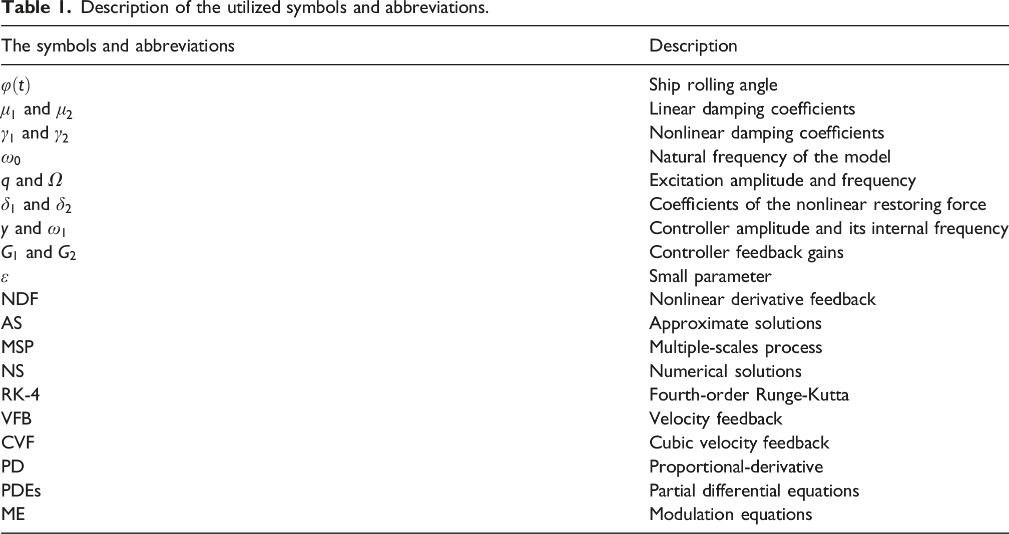
Description of the utilized symbols and abbreviations.
The closed loop feedback control with the ship dynamical model is shown in Figure 1. NDF controller with the mathematical modeling of the dynamical system.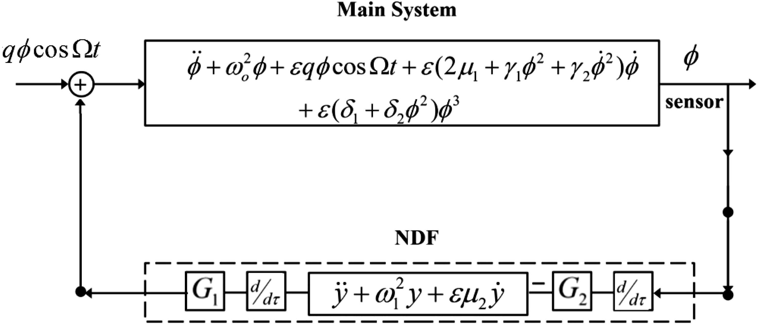
Now, we are going to apply the MSP
47
to obtain an approximate solution of equation (1) up to the second order. In MSP, a small parameter 
In this context, 
These operators explicitly demonstrate that higher-order terms, specifically those of
(a) Order 

(b) Order of 

Consequently, the general solution of equations (4) and (5) is derived as follows

Notably, 

In conclusion, we remove the previously mentioned secular terms and solve equations (6) and (7), as below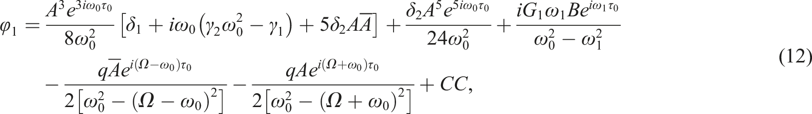

The analytical solution of the ship roll motion using the MSP plays a crucial role in understanding the system’s nonlinear dynamic behavior. This perturbation technique enables the approximation of solutions in the presence of small nonlinearities and parametric excitations, providing insight into resonance conditions, stability boundaries, and long-term behavior. Unlike purely numerical methods, the MSP yields explicit expressions that reveal how system parameters influence the roll amplitude and phase, making it a powerful tool for designing control strategies and improving the safety and performance of marine vessels under various sea conditions.
Analysis and classification of resonance
This section seeks to categorize various resonance cases, examine a particular scenario, and formulate the modulation equations (ME). Resonance conditions occur when any denominator in the final solution nears zero, resulting in singularities. Consequently, the following possibilities arise. • Sub-harmonic resonance at • Internal resonance case at
The system will behave in a complicated way if any of the resonance requirements listed above are satisfied. Additionally, it’s vital to remember that even when vibrations deviate from resonance, the resulting solutions remain valid. Let us now examine the issue in more detail, focusing on both cases of external and internal resonances that occur at 
Eliminating secular elements can yield the solvability criterion. Consequently, the subsequent equations reflect the probability of fulfilling the requirements

The established solvability conditions equations (15) and (16) contain two nonlinear PDEs for 
The first-order derivative operator may be expressed in the following form as the functions 
Based on equation (18), the following modified phase can be used to transform the solvability conditions of PDEs equations (15) and (16) into ordinary differential equations as follows
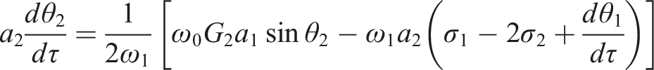
By inputting equation (17)–(19) into equations (15) and (16) and distinguishing the real and imaginary parts, we derive the following system from the prior analysis

A comprehensive explanation of the importance of constructing these equations can be provided as follows: They help capture the slow evolution of amplitude and phase in nonlinear dynamical systems, provide a simplified mathematical representation of complex vibration behaviors, and facilitate an understanding of the system’s long-term dynamics and stability characteristics. They describe the gradual changes in amplitude variations and phase shifts. The phase modulations reveal the synchronization mechanism, the coupling between different system components, and the examination of stability zones. They serve as a powerful analytical tool for understanding and predicting the intricate dynamics of controlled vibrating systems.
Steady-state approach and stability analysis
This section primarily focuses on the solutions corresponding to the steady-state condition of the dynamical system. In this context, the solutions emerge at the end of the transient processes. For this analysis, we assume 


Substituting equations (23) and (24) into (21) and (22), respectively, the resultant equations will be

Based on the analysis of the previous system equations (23)−(26) with the removal of the modified phases 


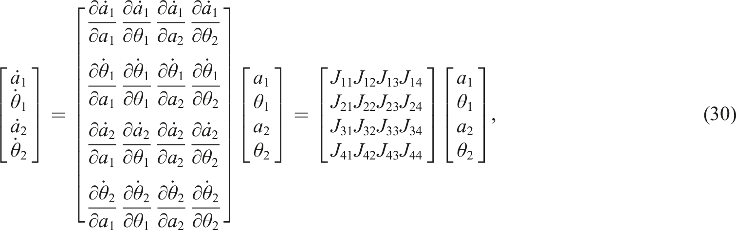
The system is formulated by linearizing equation (20) through the Lyapunov first (indirect) method, utilized to evaluate the stability characteristics of these solutions
40

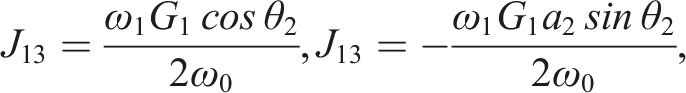


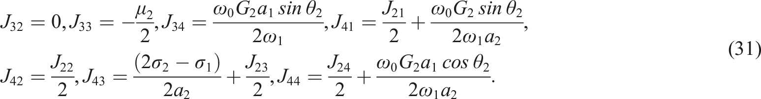
Therefore, the capacity to evaluate and resolve the characteristic equation dictates the stability of the steady-state solution. The eigenvalues of the Jacobian matrix can be expressed as follows
41
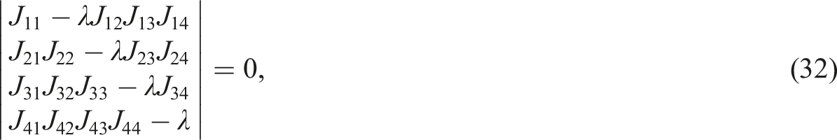


The solution is asymptotically stable if and only if all real parts of the roots of equation (33) are negative, based on the Routh–Hurwitz criterion.
41
This condition is met when the coefficients comply with
Results and discussion
In order to illustrate the system’s amplitude and phase performance, this section looks at both the controlled and uncontrolled scenarios, including the resonance state. We analyze the impact of certain elements on system amplitude. We also look at the relationship between the system amplitude and the detuning parameters, 
Time response
The RK-4 method can be applied to solve the system numerically equation (1) after incorporating the NDF control, as mentioned earlier. Figures 2(a), and (b) display, respectively, the time history of the function Time response solution Time response solution at resonance instance (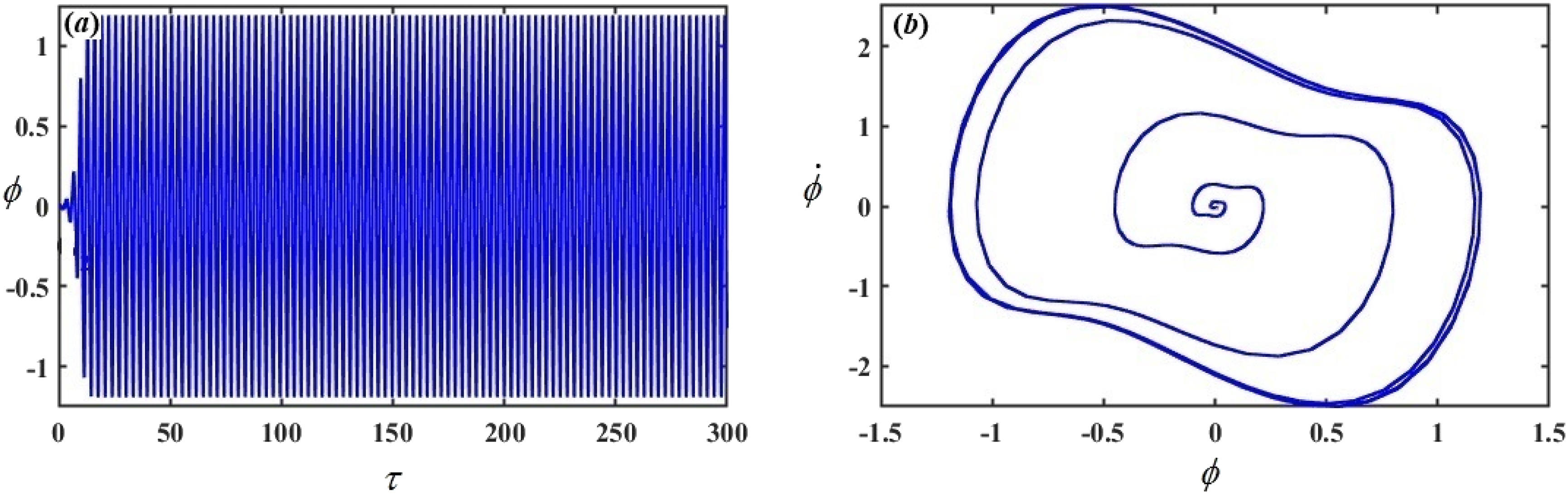
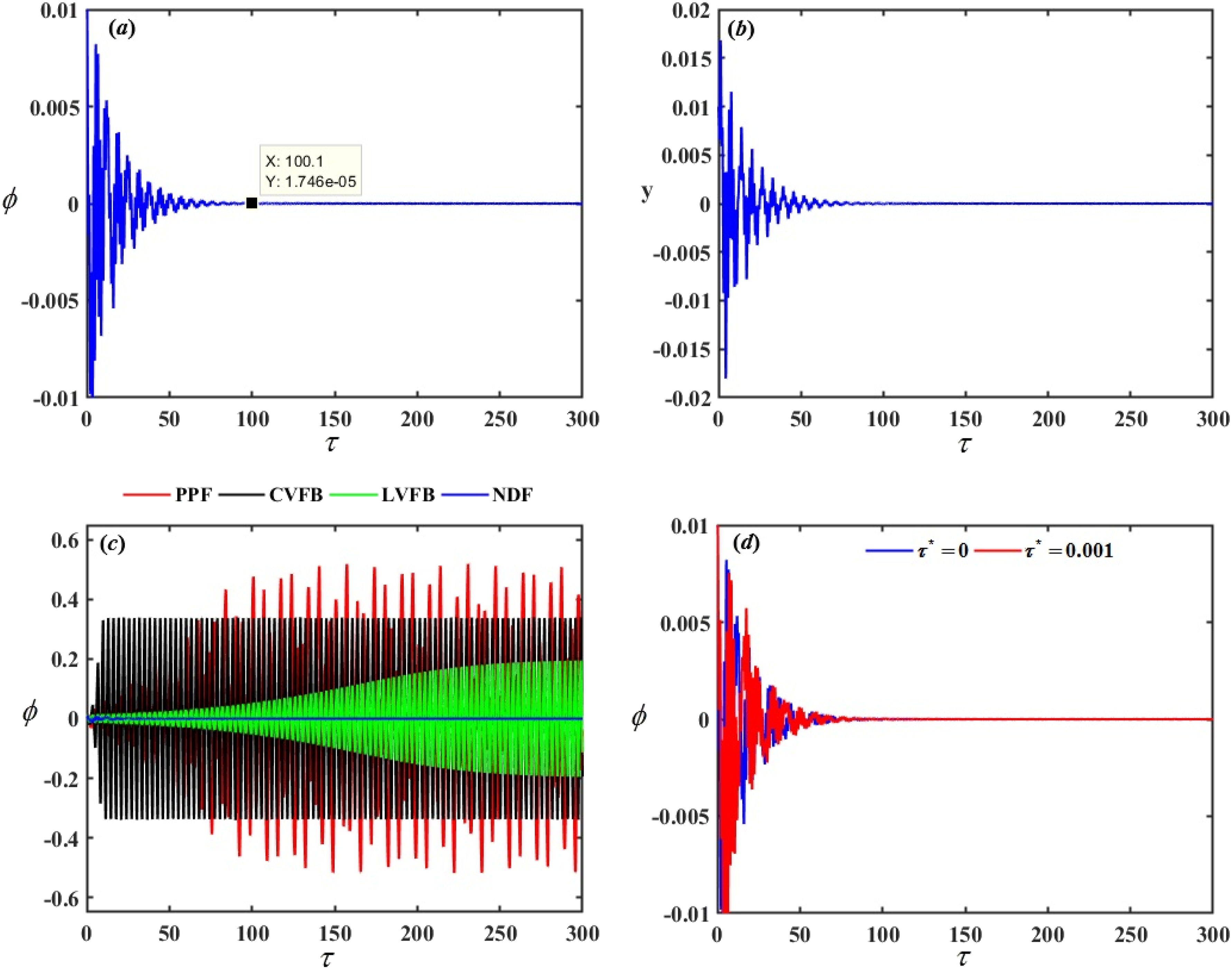
• with PPF controller is given by
• with the CVFB controller is given by the following
• with the LVFB controller is given by the following
• with the NDF controller with delay time is given by

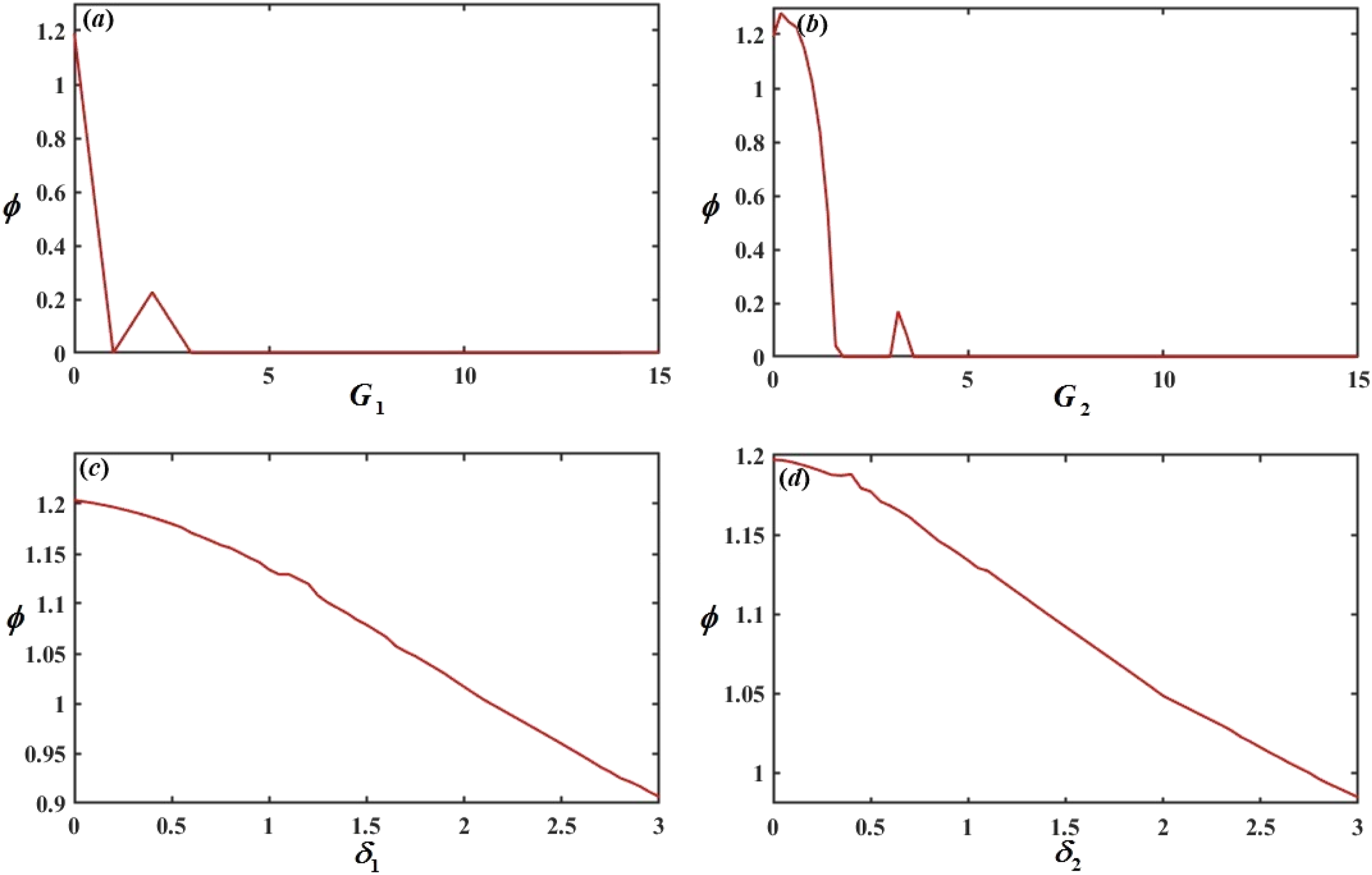
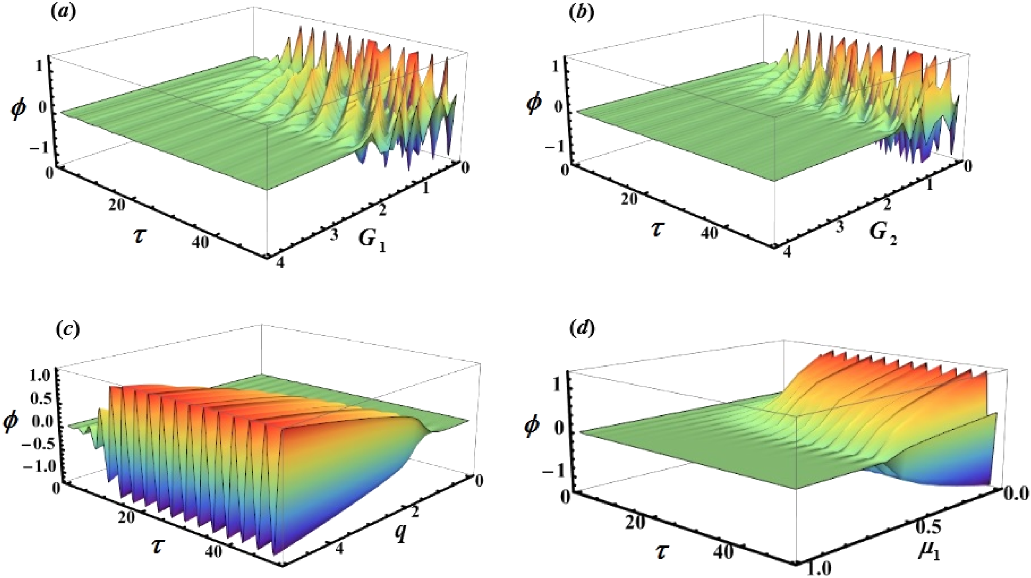
System parameter effect on the response solution
We will demonstrate how the system parameters System parameter effects System parameter effects Three-dimensional surface plot of the amplitude of the system 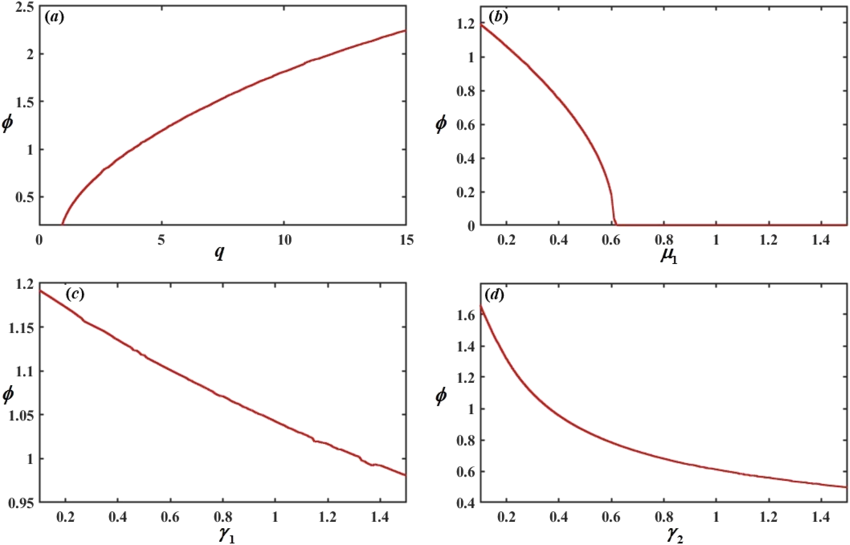
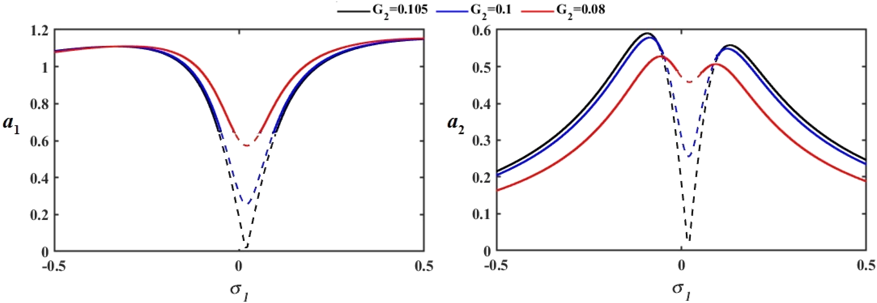
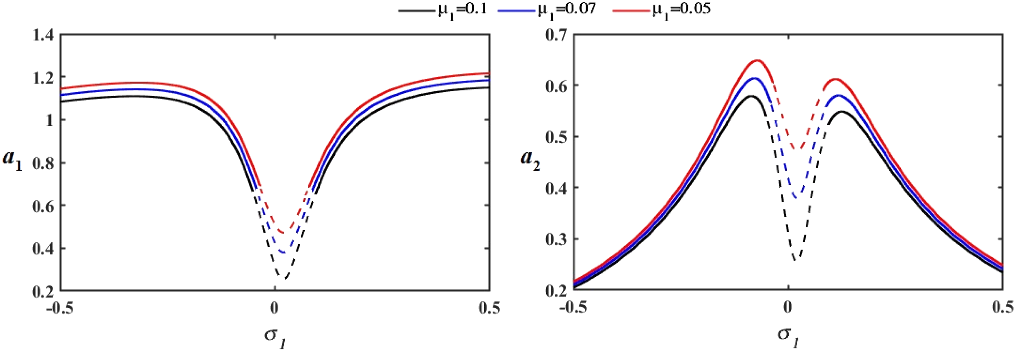
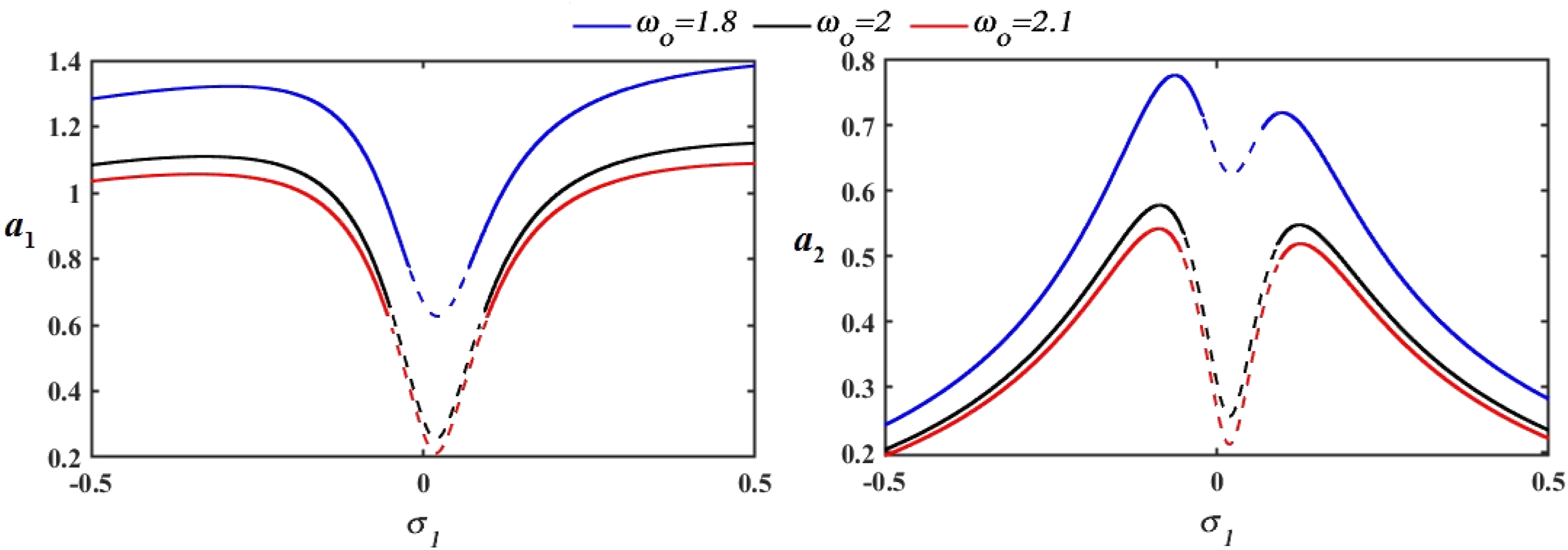
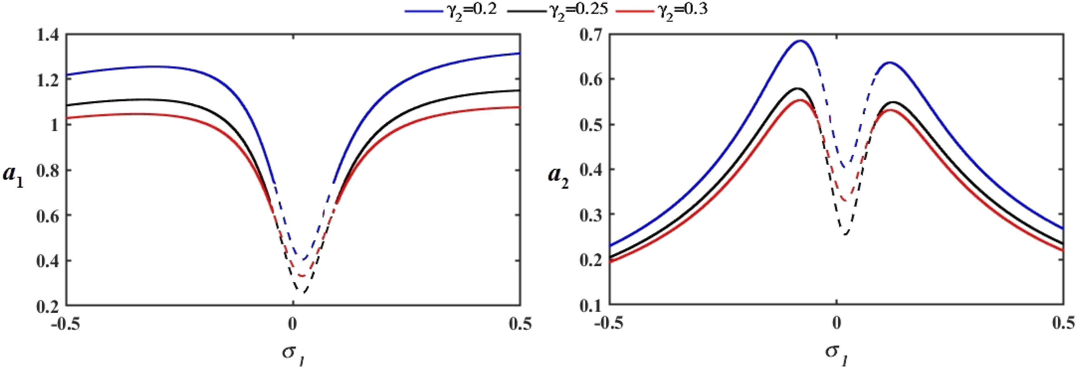
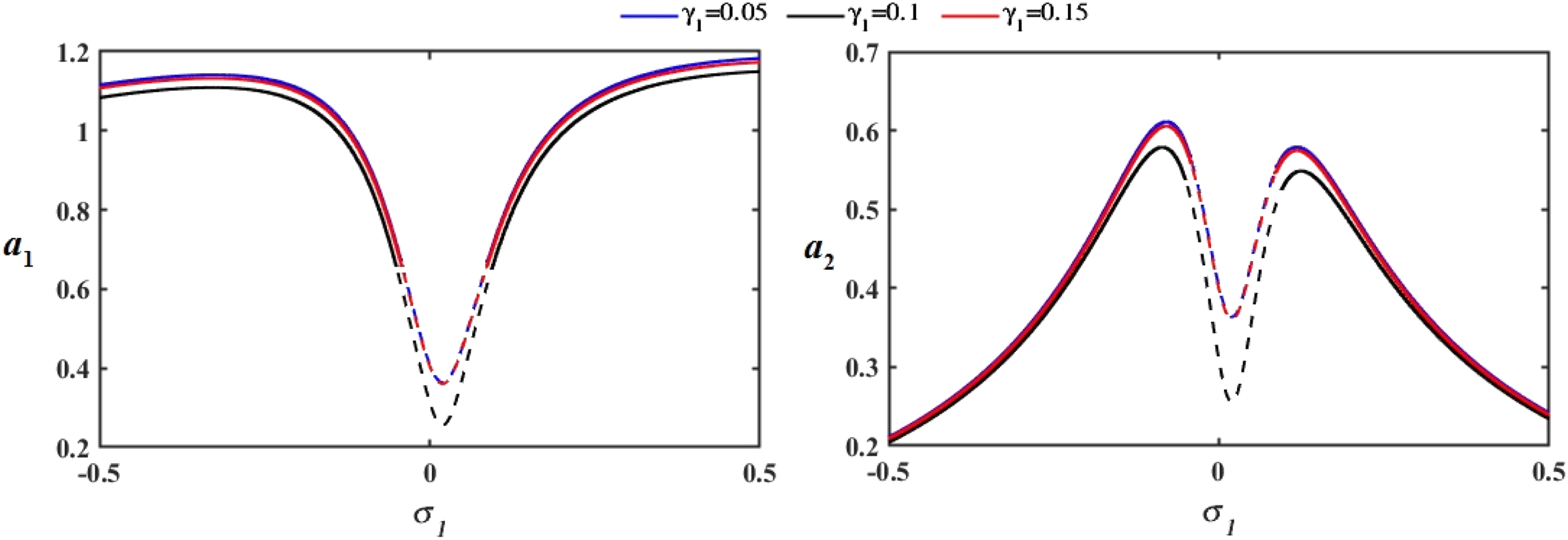
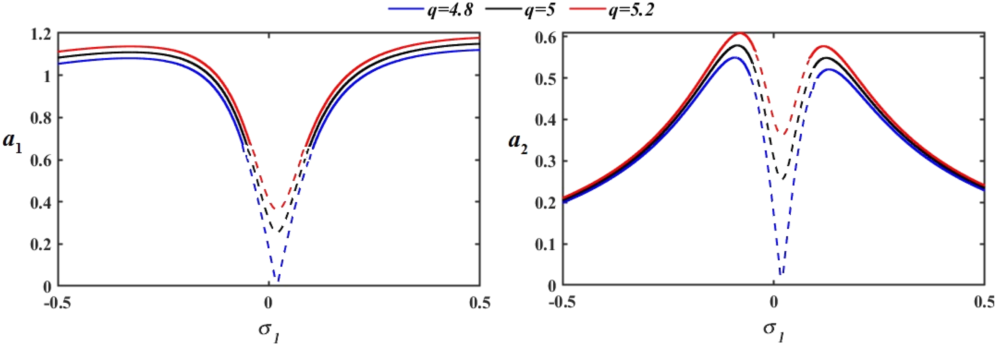
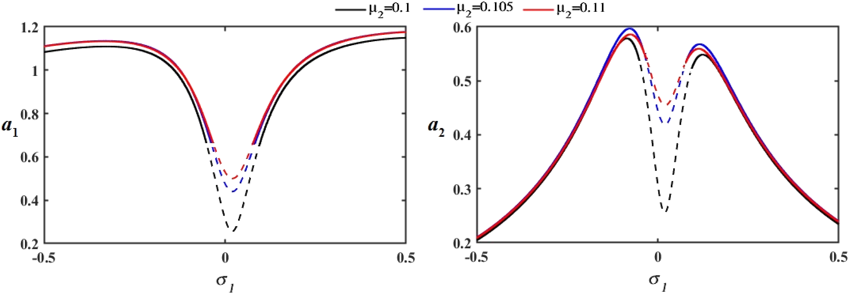
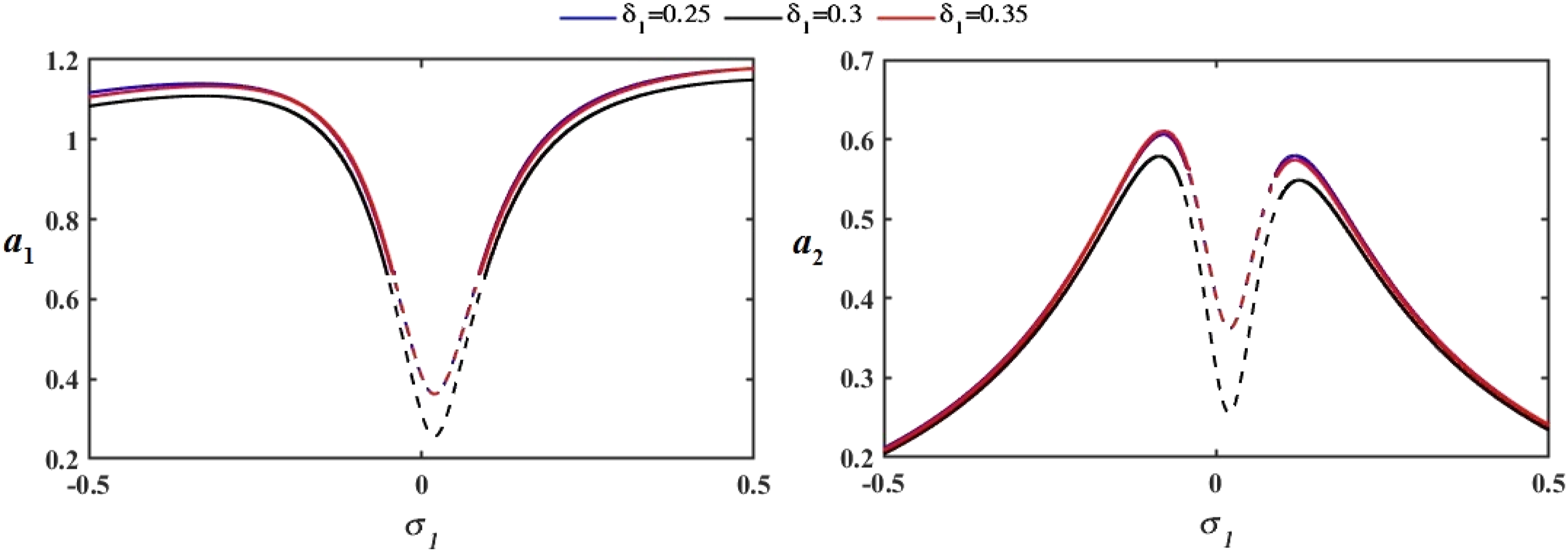
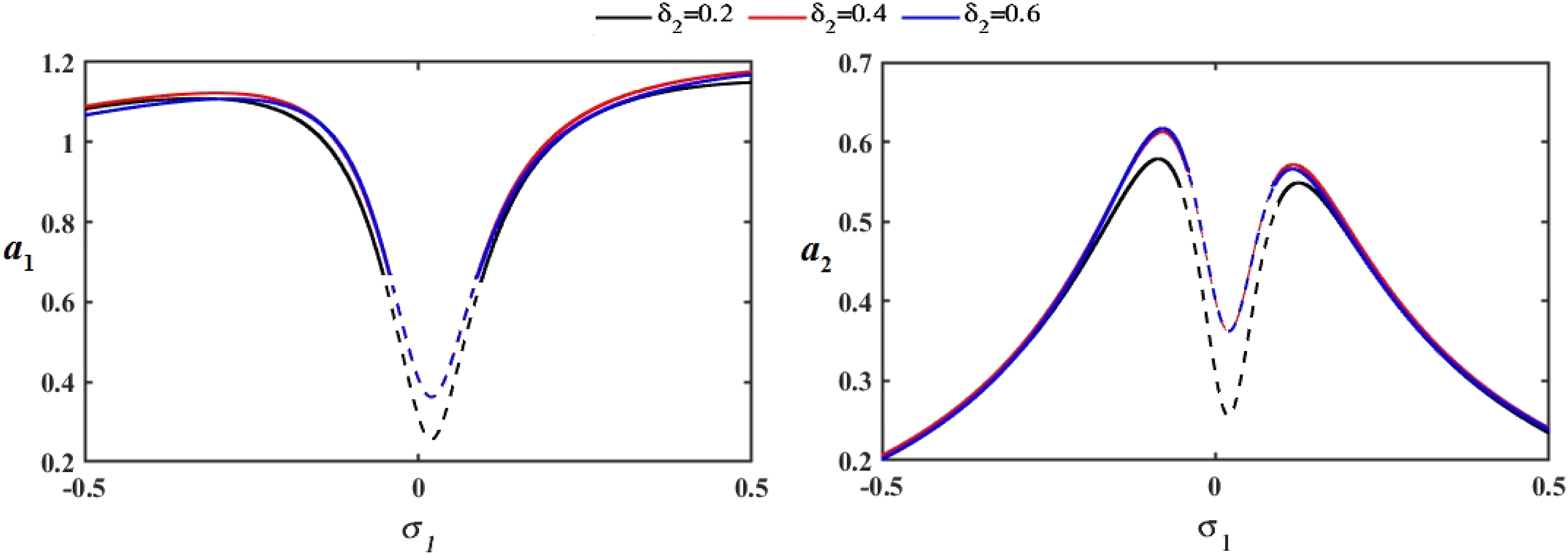
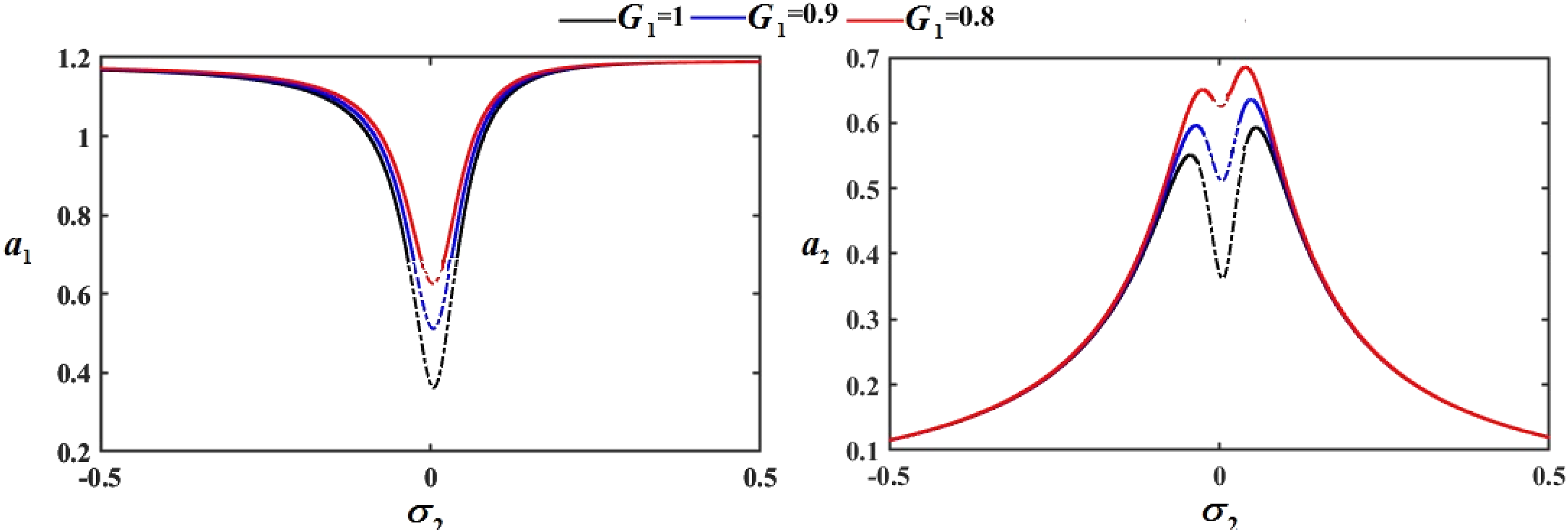
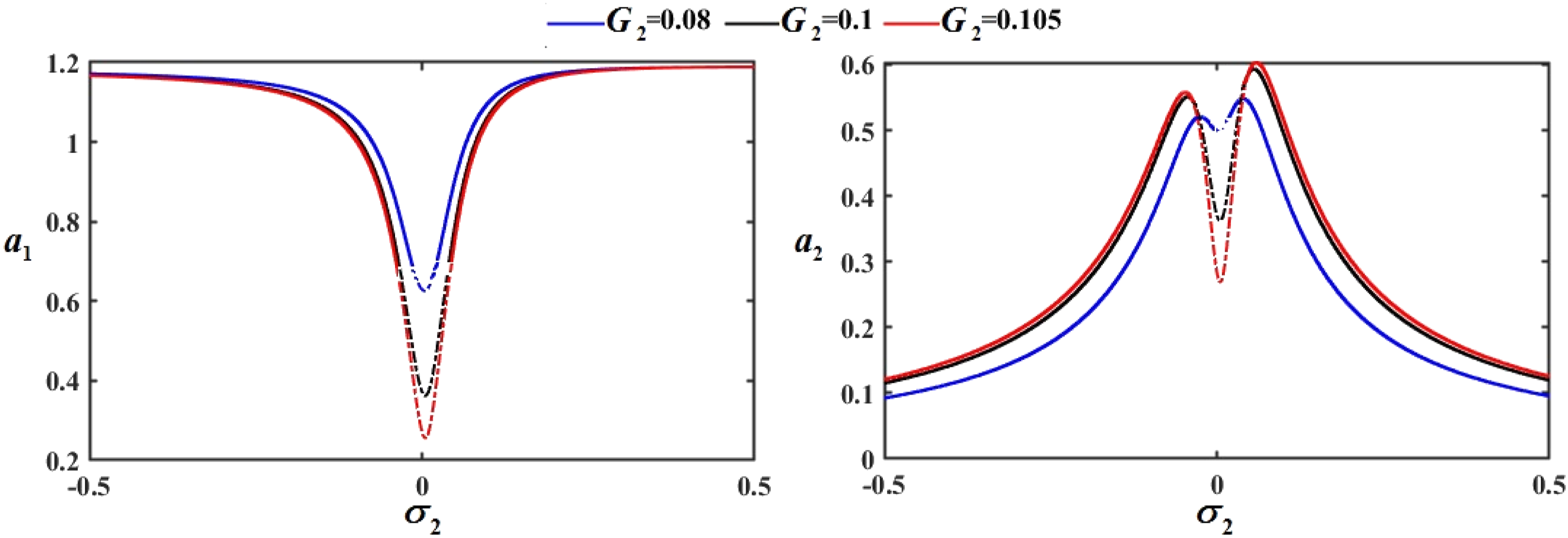
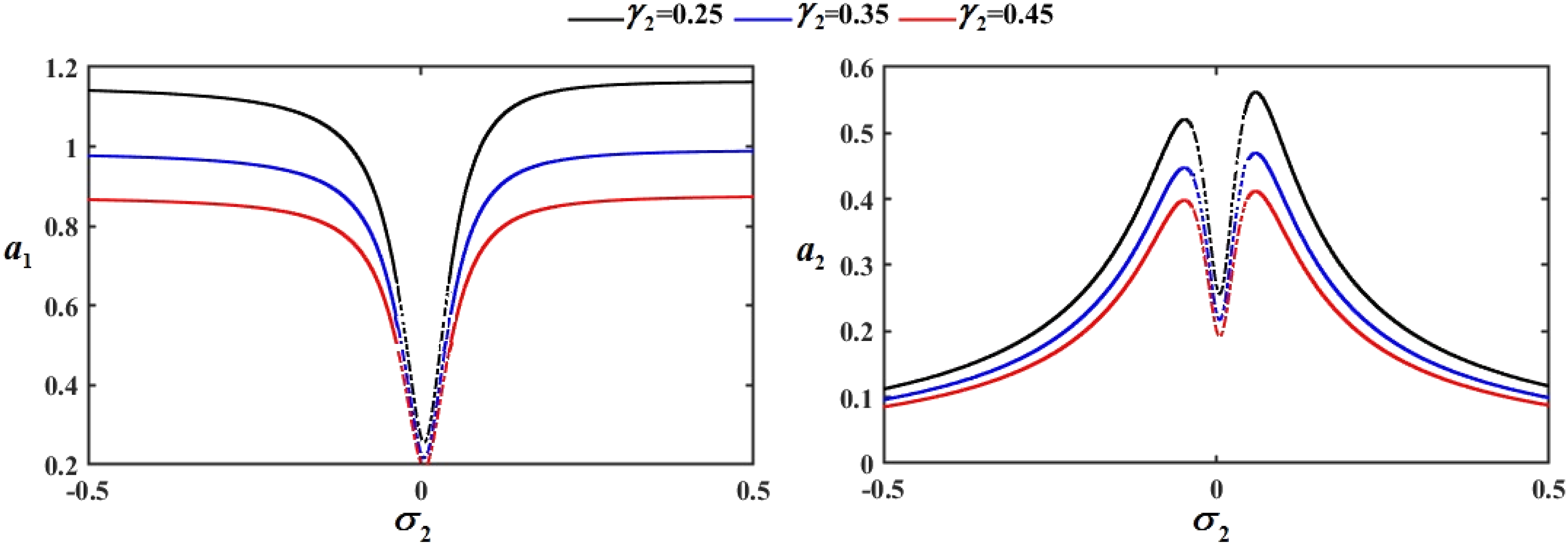
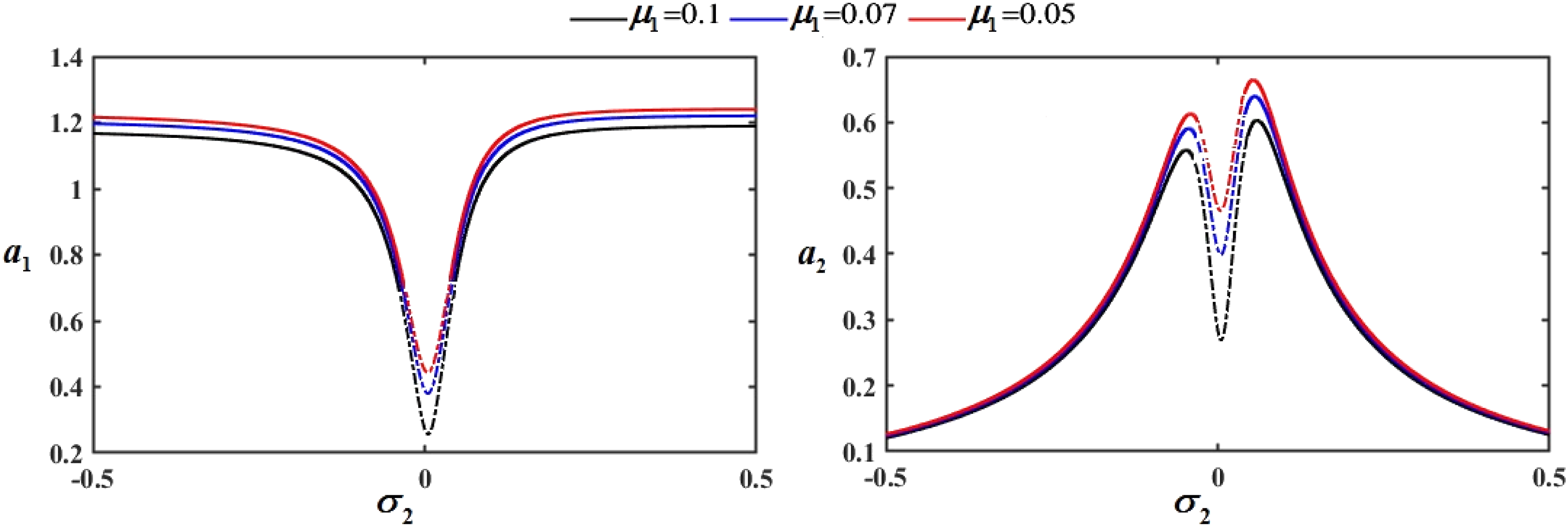
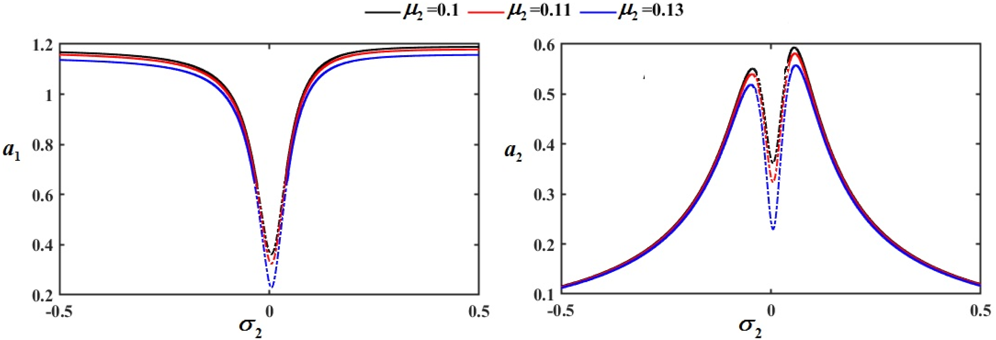
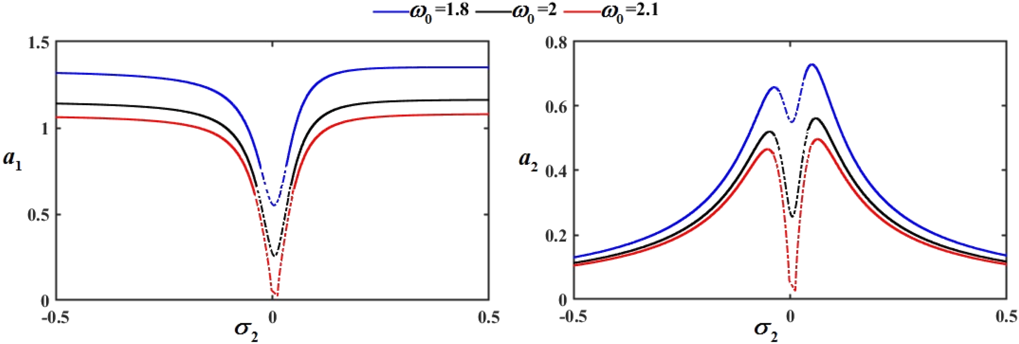
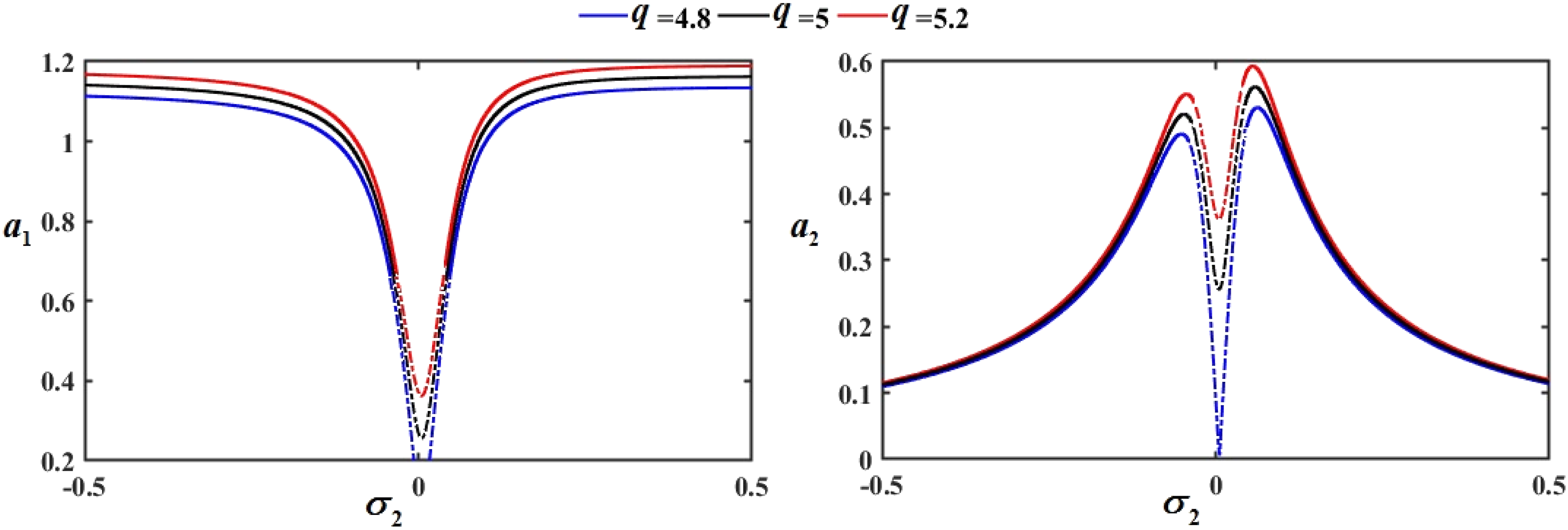
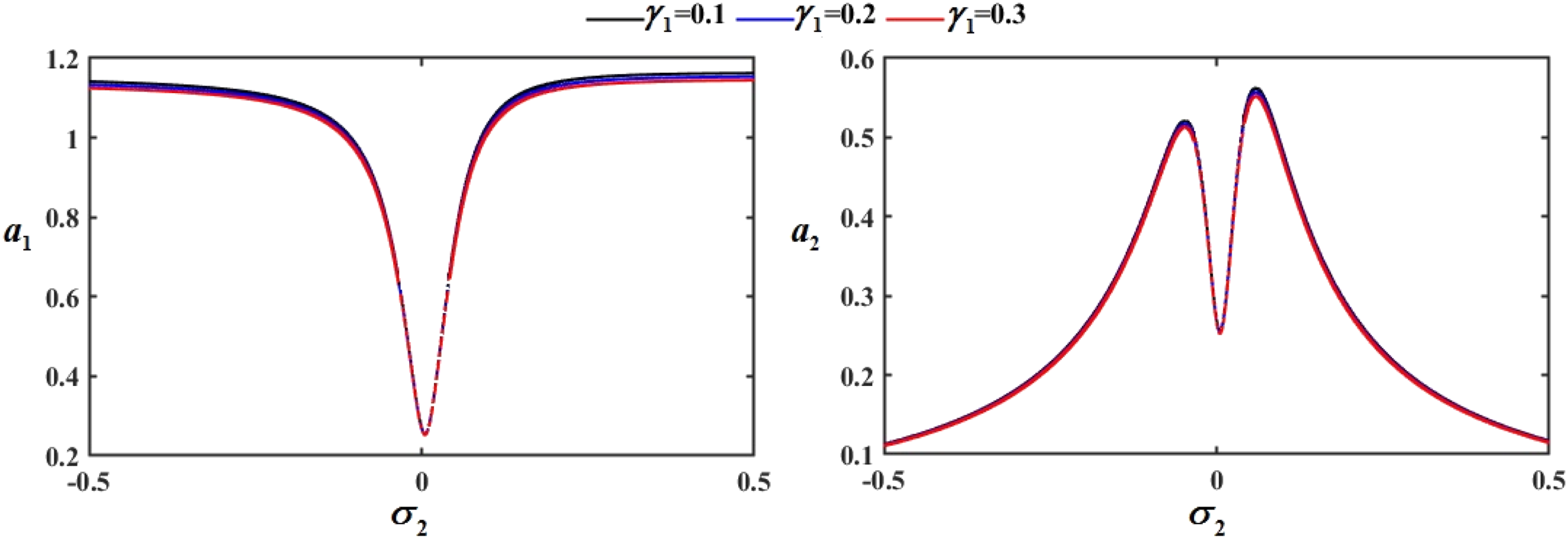
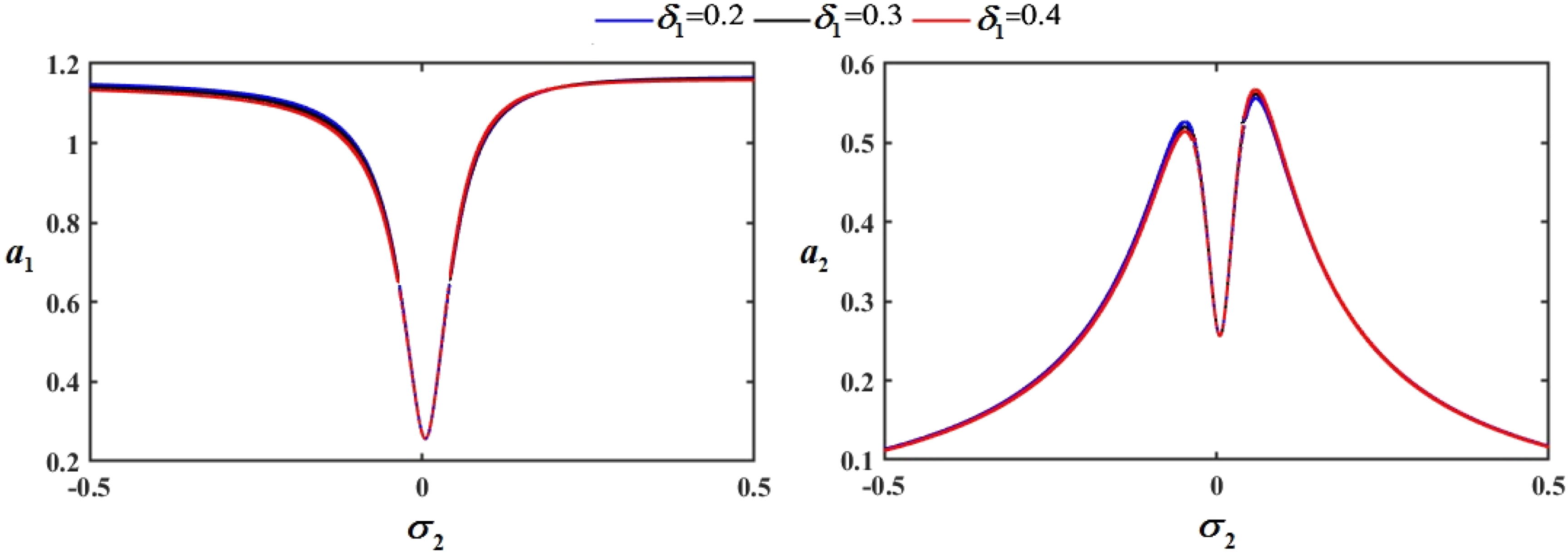
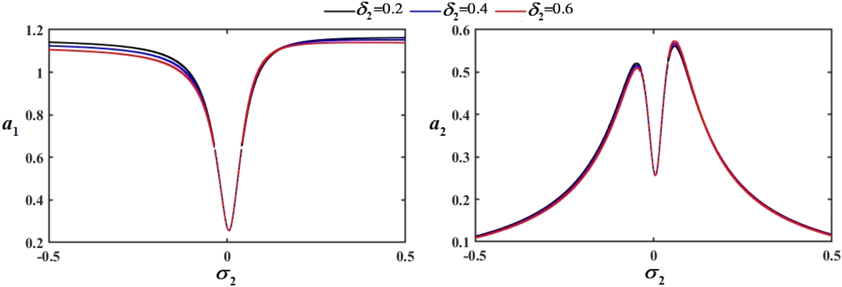
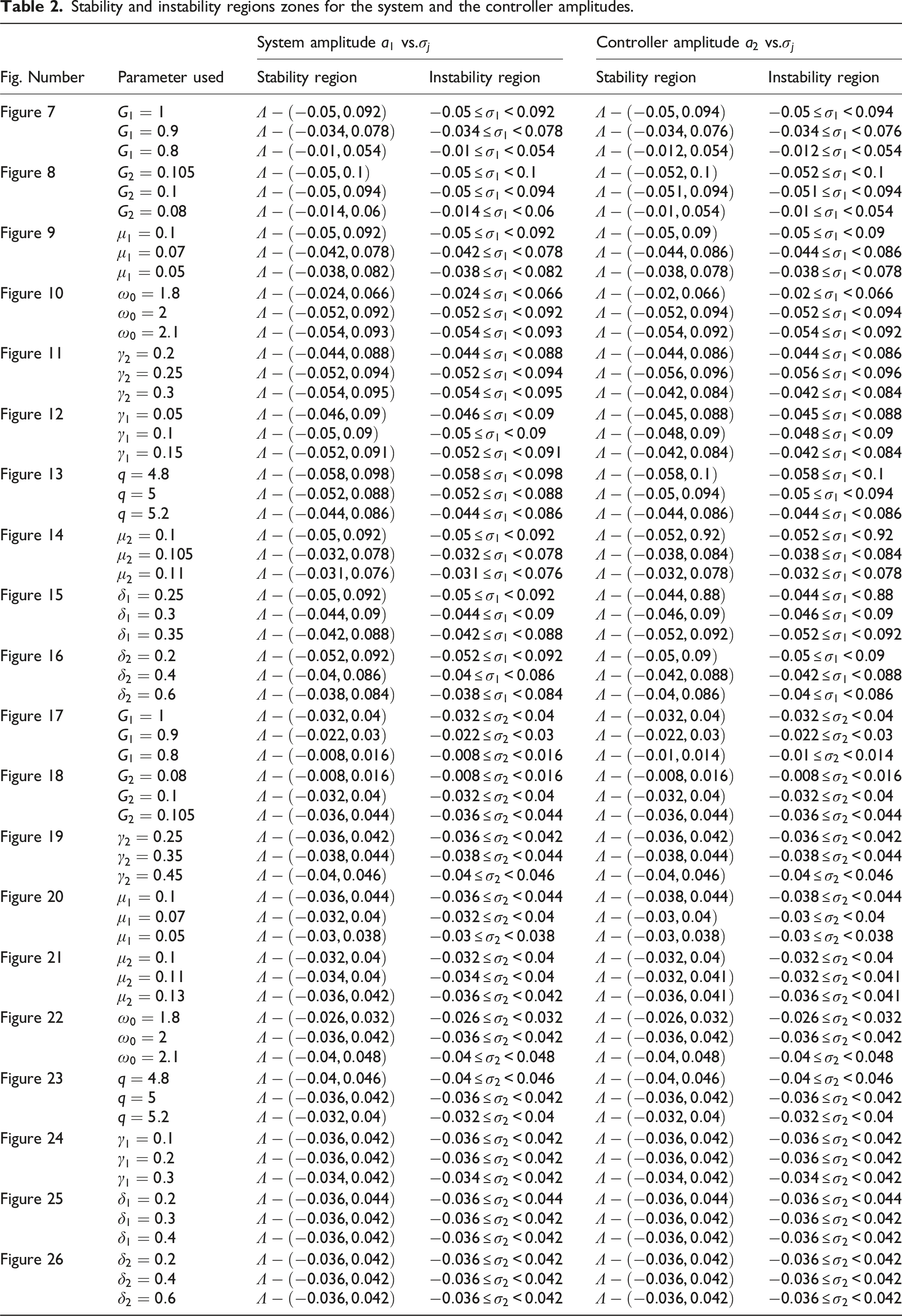
The resonant response curves
The equilibrium bands of fixed points will be demonstrated by the resonant curves of responses that are derived from the NS of equation (21), which are displayed in Figures 7–26. Consider that solid lines indicate stable fixed points while dashed lines indicate unstable ones. It has been shown that specific stability criteria parameters, such as control system gain Resonance curves for amplitudes Resonance curves for amplitudes Resonance curves for amplitudes Resonance curves for amplitudes Resonance curves for amplitudes Resonance curves for amplitudes Resonance curves for amplitudes Resonance curves for amplitudes Resonance curves for amplitudes Resonance curves for amplitudes Resonance curves for amplitudes Resonance curves for amplitudes Resonance curves for amplitudes Resonance curves for amplitudes Resonance curves for amplitudes Resonance curves for amplitudes Resonance curves for amplitudes Resonance curves for amplitudes Resonance curves for amplitudes Resonance curves for amplitudes Stability and instability regions zones for the system and the controller amplitudes.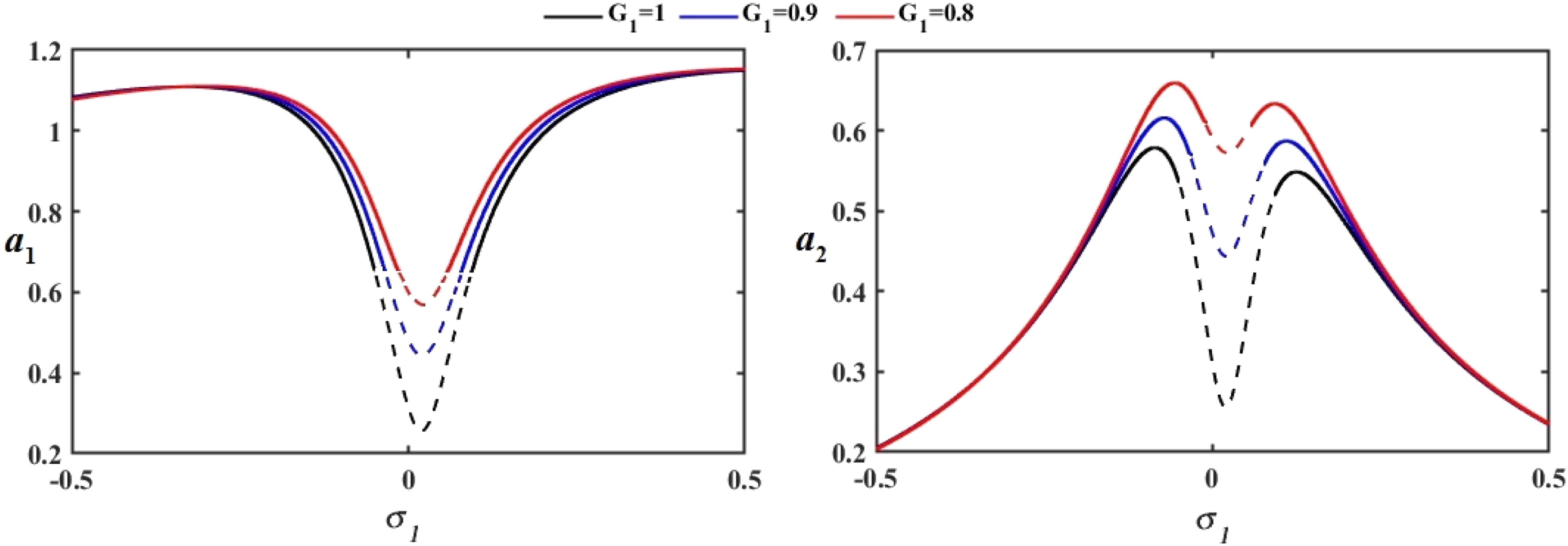
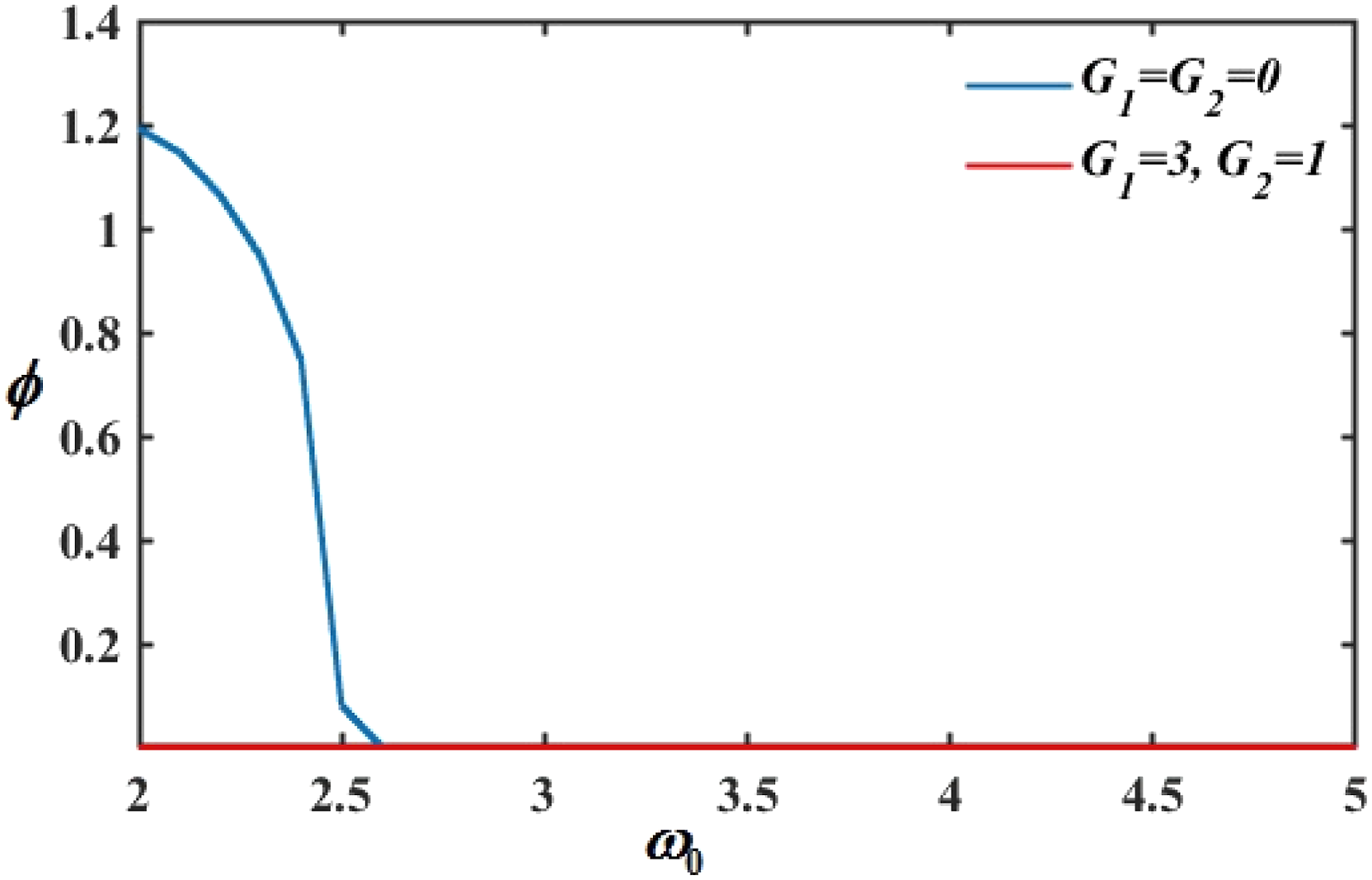
System amplitude–frequency spectrum
The frequency response curve of a dynamical system demonstrates how the amplitude of the system’s response fluctuates with the excitation range’s frequency. Figure 27 displays the amplitude-frequency behavior of the uncontrolled system under different Amplitude–frequency spectrum; Amplitude–frequency spectrum without and with NDF control.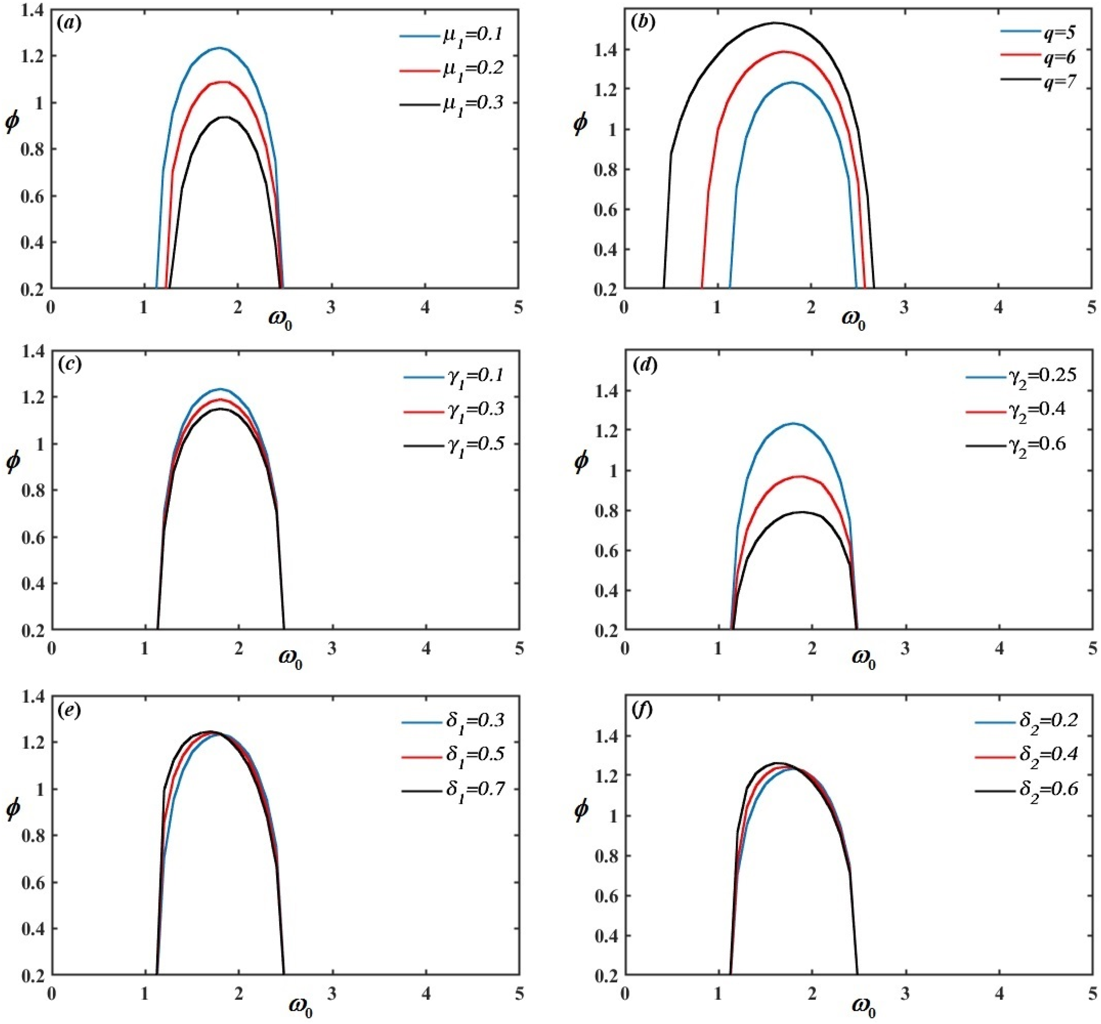
AS with NS confirmation
The AS driven by MSP and the NS utilizing RK-4 at the resonance case ( The variation between AS, shown by the blue dashed line, and NS, shown by the red line at; 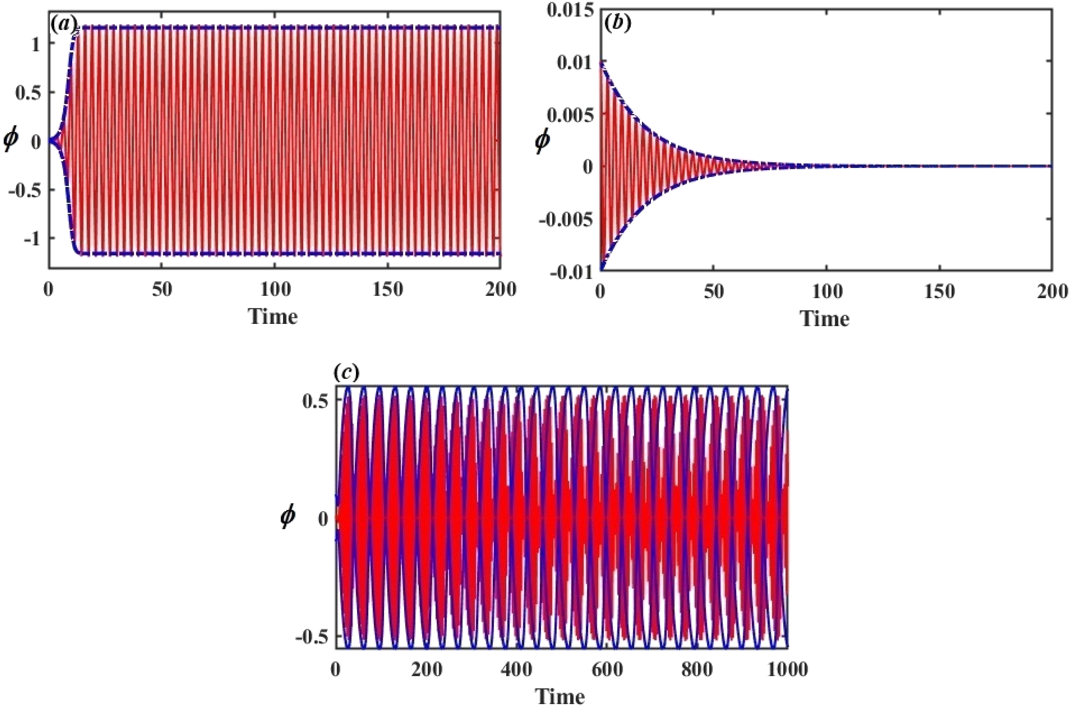
Bifurcation analysis
Bifurcation analysis plays a crucial role in understanding the behavior of nonlinear dynamical systems, particularly in identifying transitions between different types of motion, including periodic, quasiperiodic, and chaotic motion. By analyzing bifurcation diagrams, phase portraits, and Poincaré maps, one can gain deep insights into a system’s stability and dynamic characteristics as parameters are varied. These tools provide a graphical representation of how a system’s behavior changes with respect to a bifurcation parameter, revealing regions of stability, periodicity, and chaos.
In this study, we investigate the bifurcation behavior of a dynamical system by using the excitation amplitude
Bifurcation analysis without control
In Figure 30, the bifurcation diagram
48
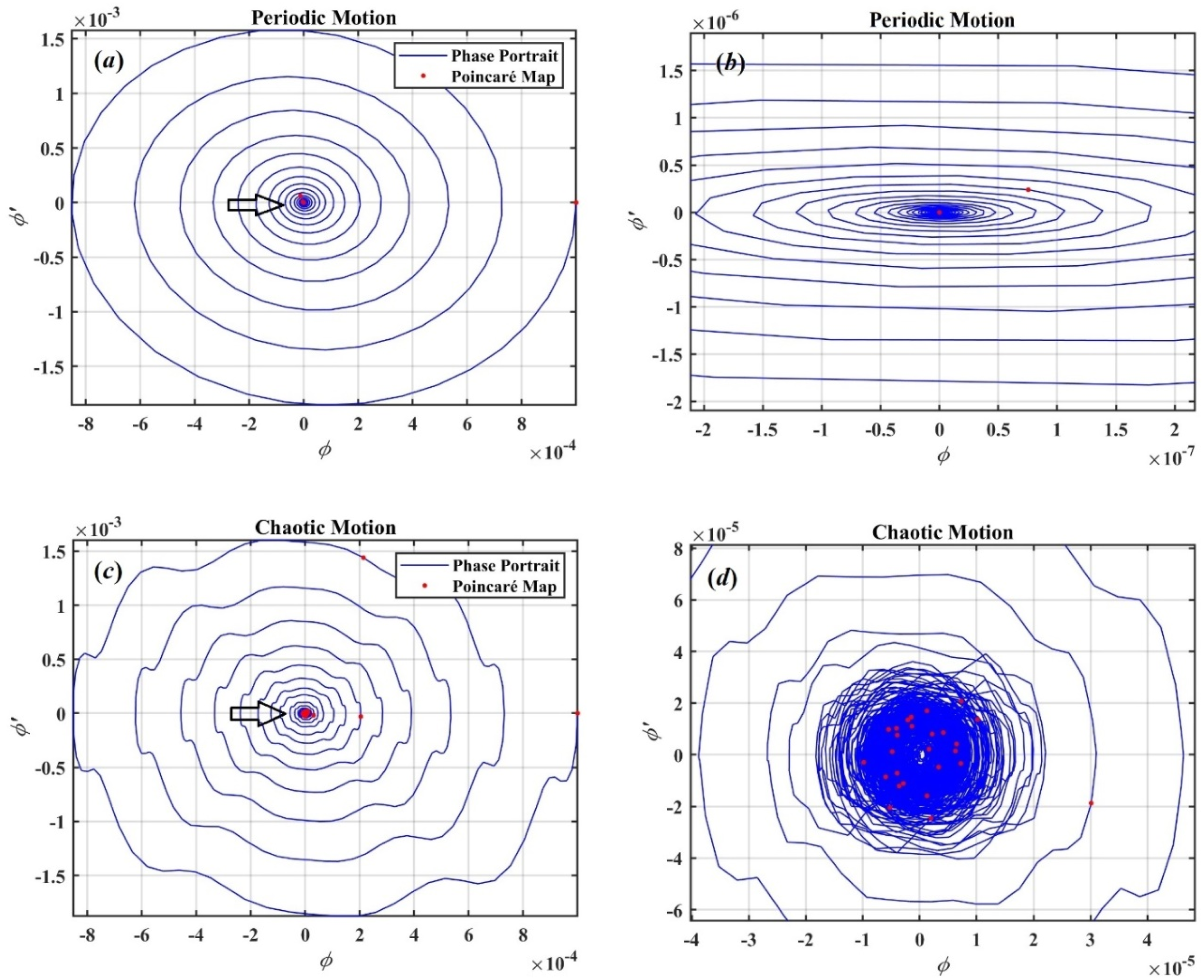
reveals two distinct types of motion. In the region Bifurcation diagram of Phase portraits and Poincaré maps illustrating two distinct types of motion: (a), (b) periodic motion at 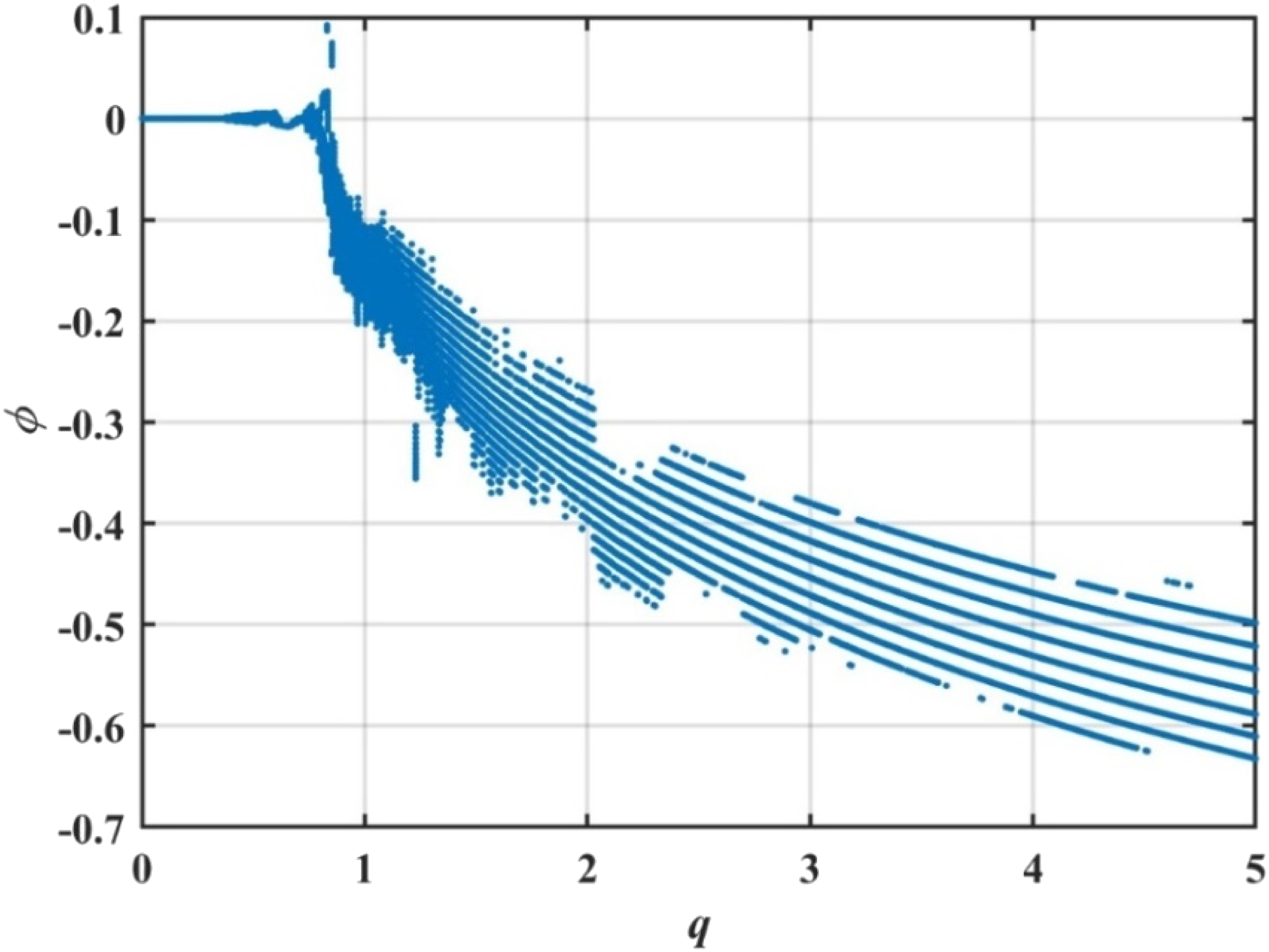
As
Without the control mechanism, the system exhibits a small region of periodic motion and predominantly chaotic behavior. This analysis demonstrates the significant role that the bifurcation parameter
Bifurcation analysis with control
Next, we repeat the bifurcation analysis, but this time with a control mechanism in place. The gain parameters are set to Bifurcation diagram of 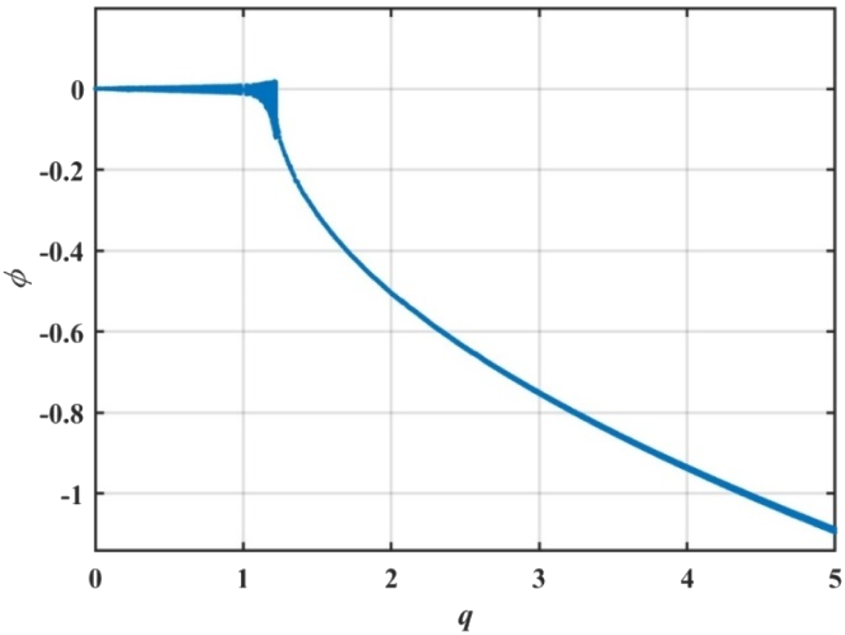
Phase portraits and Poincaré maps for the controlled system are presented in Figsure 33. These figures further demonstrate the two different types of motion. In the periodic region, the phase portraits show smooth, closed trajectories, while the Poincaré maps display discrete, evenly spaced red points, indicating periodic behavior. In the chaotic region, the red points in the Poincaré maps are scattered randomly, illustrating the system’s transition to chaotic motion. Phase portraits and Poincaré maps illustrating two distinct types of motion: (a), (b) periodic motion at 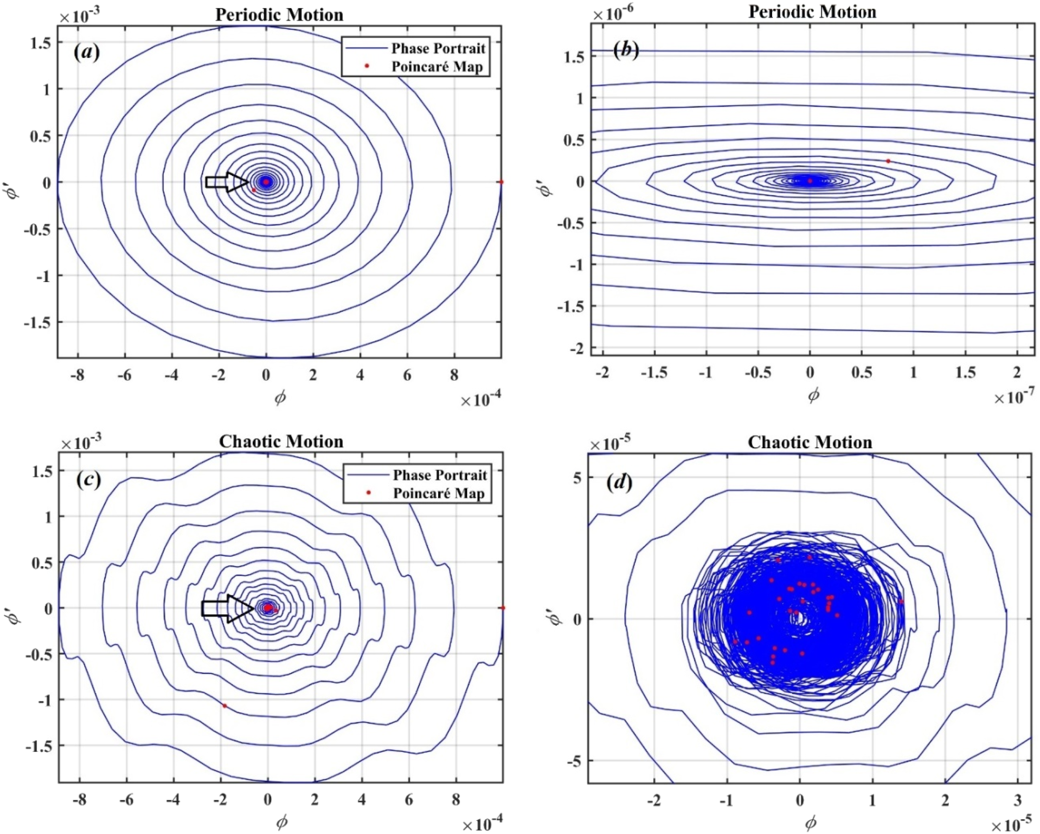
Comparison of controlled and uncontrolled systems
The comparison between the two cases, with and without control, highlights the significant impact that the controller has on the system’s dynamics. The introduction of control not only increases the stability of the system but also extends the range of periodic motion. The controlled system exhibits a larger stability region, with periodic behavior observed for a broader range of
These findings emphasize the importance of incorporating a control mechanism to enhance the stability of nonlinear dynamical systems. By increasing the range of periodic motion and reducing the extent of chaotic behavior, the controller helps maintain the system in a more predictable and stable state, which can be crucial for practical applications where reliability and control are essential.
Studying the bifurcation analysis of the ship’s dynamical system is essential for predicting and preventing irregular and potentially dangerous roll motions. Tools such as bifurcation diagrams, phase portraits, and Poincaré maps provide a deeper understanding of how the system responds to changes in parameters, revealing transitions from stable to chaotic motion. These analyses help identify critical thresholds and nonlinear phenomena that cannot be captured by linear models, thus aiding in the development of more effective control mechanisms and enhancing the safety and performance of ships in diverse marine environments.
Conclusion
This study discusses a dynamic model of a rolling ship subjected to a parametric force. Particularly in the resonance zone, the NDF control is employed to increase stability and reduce undesired vibrations. The AS is obtained by solving this equation using the MSP. By comparing the AS with the computed NS using the RK-4, the accuracy of the AS is confirmed. The ME are obtained by analyzing resonance instances and solvability requirements. MATLAB is used to graphically show the frequency responses and time histories of the solutions. Additionally, a visual comparison of the generated solutions’ time histories in controlled and uncontrolled scenarios is provided. Resonance curves are also used to describe steady-state solutions and stability analysis. The nonlinear dynamics of the model are further investigated using bifurcation analysis, illustrated through bifurcation diagrams, to identify the crucial factors that lead to qualitative changes in the system’s behavior. The Poincaré map is used to study periodic and chaotic oscillations, providing insight into the system’s long-term stability and the emergence of chaotic dynamics. At the worst resonance condition, identified as sub-harmonic resonance
We hope to work beyond routine parametric in future studies, such as extending the control strategy to full 6-DOF ship models, incorporating real sea-state data, and exploring adaptive or machine-learning-based controllers for enhanced robustness under uncertain operating conditions. These additions have been included in the revised manuscript to reflect better the practical relevance and research potential of our study.
Footnotes
Authors’ Contributions
M. K. Abohamer: Conceptualization, Methodology, Validation, Examination, Corroboration, Visualization, and Reviewing. Asma Alanazy: Resources, Data curation, Formal analysis, Validation, Reviewing. T. S. Amer: Resources, Conceptualization, Formal analysis, Methodology, Validation, Reviewing, and Editing. Taher A. Bahnasy: Investigation, Methodology, Corroboration, Validation, Data duration, Examination, Visualization, and Reviewing.
Funding
The authors declared the following potential conflicts of interest with respect to the research, authorship, and/or publication of this article: The authors extend their appreciation to the Deanship of Scientific Research at Northern Border University, Arar, KSA for funding this research work through the project number “NBU-FFR-2025-912-03”.
Declaration of conflicting interests
The authors declared no potential conflicts of interest with respect to the research, authorship, and/or publication of this article.
Data Availability Statement
All data generated or analyzed during this study are included in this published article.