
Abstract
A quasi-zero stiffness vibration isolator (QZSVI) is used in applications like precision instruments, aerospace, microelectronics manufacturing, and seismic isolation to protect sensitive equipment from low-frequency vibrations. Their key advantage lies in achieving near-zero stiffness, allowing for highly effective vibration attenuation while maintaining system stability. These passive systems are cost-effective and reliable, offering superior vibration isolation without the need for external power or active control. This work proposes the use of negative displacement, velocity, and cubic velocity feedback control techniques to enhance the QZSVI’s isolation performance. We found that the composite negative velocity and cubic velocity control (NVFC + NCVFC) is more effective with low cost compared to other types of controller (its effectiveness is about 94.8%). The approximate solutions (AS) of the controlling system of equations of motion (EOM) are acquired using a multiple-scales procedure (MSP) up to the second order, and it is subsequently validated numerically through the Runge–Kutta method (RKM) from the fourth-order. Modulation equations (ME) are obtained by exploring resonance instances and solvability conditions. Time history graphs and frequency response curves, generated via MATLAB and Wolfram Mathematica 13.2, are presented to analyze stability and steady-state solutions. It is investigated how altering the parameters affects the system amplitude. Poincaré maps, Lyapunov exponent spectra (LEs), and bifurcation diagrams are presented to illustrate the system’s diverse behavior patterns. Furthermore, the transmissibility of force, displacement, and acceleration is computed and displayed. A QZSVI minimizes low-frequency vibrations, making it ideal for precision applications in metrology, automotive, aerospace, civil engineering, medical equipment, and renewable energy. It achieves superior damping, ensuring high stability and precision.
Keywords
Introduction
The QZSVI is sophisticated passive vibration isolation equipment that is intended to reduce vibrations, particularly at low frequencies where conventional isolators sometimes have difficulties. Classical isolators, like dampers or springs, frequently have to choose between vibration isolation and weight-carrying capability. In order to handle big loads, a higher stiffness is required; nevertheless, this decreases the system’s capacity to isolate low-frequency oscillations. To get past this restriction, QZSVI systems combine linear and nonlinear components, such as buckling beams or pre-compressed springs, and provide virtually “flat” stiffness characteristics around the position of equilibrium. As a result, the system is able to support loads efficiently and provides excellent isolation at lower frequencies. Extended exposure to vibration and impact can lead to discomfort and fatigue in the human body in vehicle engineering. In the fields of mechanical and architectural engineering, excessive vibrations can cause structural damage, making vibration control a critical focus. Linear passive vibration isolators are frequently employed due to their affordability and effectiveness in managing vibrations. Vibration control is vital in engineering to reduce harmful effects. Metamaterials and origami-based structures offer unique properties like energy absorption and negative stiffness, making them effective solutions. Though distinct, their overlap has led to combined concepts like “origami metamaterials,” blending mechanical and structural innovations. 1
A bio-inspired limb-like construction with asymmetry bars and springs is studied in Ref. 2 for passive vibration isolation. Flexible quasi-zero, zero, or negative stiffness can be achieved by adjusting the system’s nonlinear stiffness through structural factors. The asymmetric design and spring ratios improve stiffness tuning and loading capacity. Its benefits over current isolators are confirmed by experiments, providing a novel approach to designing vibration control. In Ref. 3, the authors looked at how applying higher-order expansions improved these reactions. In Ref. 4, a three-degrees-of-freedom (DOF) system impacted by harmonic excitation forces was created by analyzing the movement of a tuned absorber attached to a 2DOF pendulum mechanism. The fundamental resonance is examined, and the system’s stability is analyzed utilizing the function of frequency response and the phase plane approach.
In Ref. 5, it is suggested to use a displacement–velocity feedback regulation technique to improve QZSVI’s isolating capability. In the electronically controlled QZSVI mechanism, the delay in time is taken into account. All potential improvements to optimize the QZSVI for better overall performance are outlined in Ref. 6, along with a few engineering examples demonstrating its applications. The dynamic model in Ref. 7 was constructed using LE, and new indicators for the QZSVI are developed and compared with other isolators, considering stiffness linearity and the region’s width. The theoretical results are then confirmed through the establishment of an experimental setup. The authors study the worst resonance case of a Duffing oscillator under feedback control using MSP in Ref. 8. The effects of time delay on amplitude and stability analysis were examined. In Ref. 9, a shearer magnetic braking system with multi-excitation forces is studied and solved by MSP. The worst resonance case, with NVFC showing 99.95% control effectiveness, outperforming NCVFC at 96.7%. In Ref. 10, the NVFC is used to reduce vibrations in the 2DOF system. Bifurcation diagrams, Lyapunov exponents, and piezoelectric EH performance are investigated. In Ref. 11, the behavior of an elastic pendulum under harmonic forcing is examined, with its pivot point following a circular trajectory at a steady angular velocity. In a dynamical pendulum system, where the suspension point follows a Lissajous curve trajectory, the energy transfer between various modes is depicted in Ref. 12. In Ref. 13, the authors conducted an analysis of a suspended mass connected to a nonlinear damped spring pendulum, one end of which was anchored to a fixed location. Both transverse and radial forces exerted on the spring have an impact on the motion. Two distinct strategies involving three different time frames are used in Ref. 14 to enhance the findings of Ref. 13. These scales are thought to be necessary for lowering errors. In these investigations, the EOM were estimated using the MSP Ref. 15. The vibrating movement of a damped pendulum of a rigid body at its equilibrium point is examined numerically in Ref. 16. One of the energy harvesting technologies that transforms vibratory movement into electric energy is an electromagnetic device. In Ref. 17, the vibratory movement of a connected dynamical system to this device is explored. In Ref. 18, the authors examined how a spring pendulum coupled to a more basic one-damped motion. In Ref. 19, the researchers investigated how a viscous moment at the turning point and two harmonic excitation forces affected the movement of a pendulum system. In Ref. 20, authors examined the pivot movement of a basic pendulum that was traveling on an elliptical path and had a stiff arm attached to a longitudinal absorber. By adding regional averages and replacing rapid scale inputs with localized periodic-in-time problems, the authors 21 were able to decouple the rapid and sluggish scales. By breaking down errors into averaging error, slow scale error, and fast scale error, they were able to create an a posteriori error estimator through the use of the dual-weighted residual approach. The writers verified the error estimator’s accuracy and demonstrated how to use it for adaptive control of a numerical MSP.
In Ref. 22, the nonlinear oscillation of a dual pendulum with 2DOF that is not stretched and whose suspended point travels in an elliptic path at a constant angular velocity is studied. These pendulums are connected with varying masses and vary in length. The EOM are derived by applying Lagrange’s equations (LE). Up to the third level of approximation, the desired AS are found using the MSP. The planar movement of a distinct 3DOF triple pendulum system is explored in Ref. 23, featuring a double rigid pendulum linked to an unstretched pendulum that is suspended from a fixed point. The controlling system of EOM are developed by using LE. Utilizing the MSP, higher-order AS of these equations are obtained. On the other hand, using the Galerkin method, time and displacement variables are uncoupled, and the resulting ordinary differential equation (DE) governing the web’s behavior is solved using the MSP. In Ref. 24, the authors explored the creation of a nonlinear model for the meniscus force acting on the trolling mode atomic force microscopy (TR-AFM) nanoneedle and presented an analytical solution by applying the MSP technique to the distributed-parameter model of the TR-AFM resonator. A nonlinear railway car with dual bogies was the subject of a bifurcation analysis in Ref. 25 to examine how the interaction between the bogies affects the hunting behavior of the vehicle. By means of an asymptotic growth of a minor perturbation parameter through the MSP, solutions close to the hunting speed were produced. Resonance cases are commonly classified, with a specific emphasis on studying the circumstance involving two simultaneous external resonances. A damped elastic pendulum, as opposed to an unstretched one, is the subject of additional research on this subject, as described in Ref. 26. A two-scale feed-forward control approach was studied in Ref. 27 using the MSP to lessen undesired residual oscillations in both standard and non-traditional duffing systems. In Ref. 28, the authors applied the method of restricting phase trajectories to explore the dynamics of a parametric pendulum for the stationary and non-stationary scenarios. They suggested a simplified model that might predict highly modulated patterns beyond the usual range of initial conditions. In Ref. 29, it was performed a multi-scale dynamic analysis and established solvability criteria for 1D structures with irregular boundaries, making it easier to examine beams, arches, strings, and cables. In Ref. 30, the presented study is focused on the impact of forced oscillations on a coupled particle to a support by means of two nonlinear springs with viscous dampers. The MSP is used in the time domain in this investigation. However, new algorithms designed specifically to handle differential and algebraic equation problems have resulted in a modified version of the MSP with three scales of the time variable. In Ref. 31, the authors investigated the sinusoidal response of vibrating rods equipped with a variety of nonlinear springs. Response functions are shown over wide frequency ranges in the multi-mode analysis to reveal different resonances.
In Ref. 32, the effect of a piezoelectric device on a 2DOF dynamical system is investigated. LE are applied to get the system’s governing EOM, while the AS was obtained using the MSP, and the NS was derived via the RKM. Secular terms are eliminated to establish solvability criteria, and the various resonance cases are then classified. The ME for two cases are investigated, and the outputs of the energy harvesting device are analyzed. In Ref. 33, the vibrating dynamical motion of a 3DOF auto-parametric system made up of a damped spring pendulum and a damped Duffing oscillator is investigated. The EOM are derived by applying LE, and the MSP are employed to solve this equation. In addition, the study looks into non-linear stability and analyzes resonance cases, time histories, resonance curves, and stability zones. Furthermore, the influence of an electromagnetic harvesting device on another 3DOF dynamical system is examined in Ref. 34. The EOM of the system are solved analytically utilizing the MSP. To determine the areas of instability and stability, the conditions of Routh–Hurwitz are applied. In Ref. 35, the authors examined the influence of three external moments on the movement of a 4DOF nonlinear system. LE and the MSP have been used to get the system’s EOM and to obtain its solutions. The corresponding NS of this system are obtained using RKM, demonstrating high consistency and precision. Graphs representing the motion’s time histories, resonance curves, and the solutions at the steady-state case are used to explore how the physical properties of the system affect the motion under study.
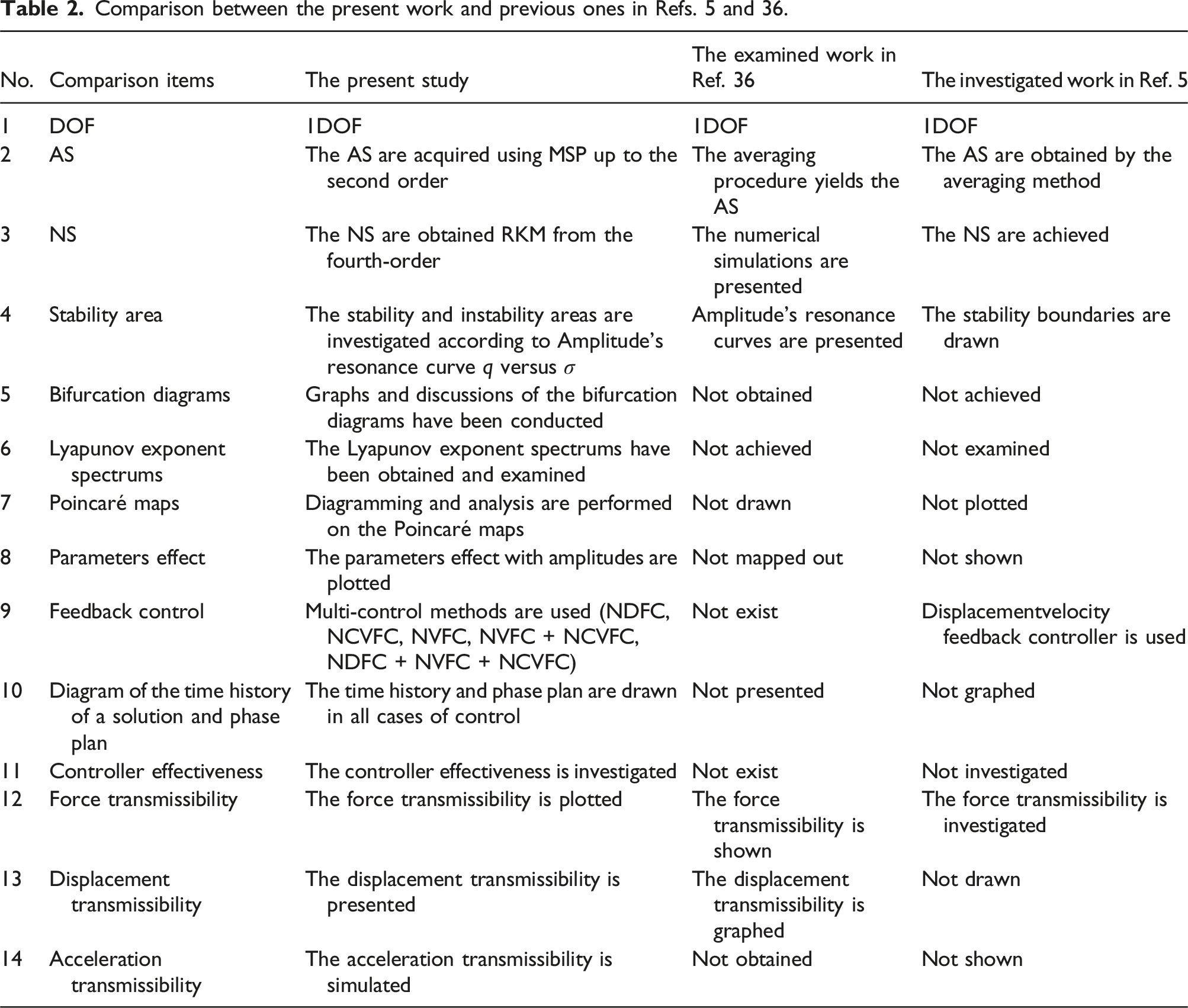
The purpose of this study is to introduce efficient feedback control techniques for reducing vibration in the resonant area. To fulfill that goal, a negative displacement feedback controller (NDFC), a negative velocity feedback controller (NVFC), a negative cubic velocity feedback controller (NCVFC), a NVFC + NCVFC, and composite controllers NDFC + NVFC + NCVFC methods are suggested in this article. Using the MSP, the system’s AS are derived till the second-order approximation. To evaluate the accuracy of the used approach, the NS are calculated using the RKM, graphically represented, and compared to the AS. The solvability criteria and all resonance cases are found when the secular terms are eliminated. Informed of the numerical solutions of the ME’s stability assessments, the temporal histories of the modified phases and amplitudes are displayed. These equations are simplified under steady-state conditions to obtain the frequency response equations, which are subsequently solved together to identify the fixed points. Consequently, the resonance curves at various parameters are used to display the associated domains of stability and instability. In addition, bifurcation sketches, Poincaré maps, and LEs are used to explore the system’s behavior. The transmissibilities of force, displacement, and acceleration are computed and displayed. In domains demanding high precision and stability, such as seismic isolation, precision instruments, and aerospace systems, QZSVI is extensively employed to safeguard delicate equipment from low-frequency vibrations. Their superior isolation capabilities without sacrificing stability make them perfect for situations where minimum external vibration disturbance is required.
The approach and analysis of a QZSVI with negative displacement, velocity, and cubic velocity feedback control techniques to improve the QZSVI’s isolation performance highlight the innovations of this study. Another innovative feature is the use of the MSP to derive the AS up to the second order, which enables a more precise and thorough investigation of the dynamic behavior of the system, especially when nonlinearities are present. By contrasting the AS with the NS derived from the fourth-order RKM, the study confirms the correctness of the AS. This two-pronged strategy guarantees the robustness and dependability of the analytical techniques used. Using force, displacement, and acceleration transmissibility, bifurcation diagrams, Poincaré maps, and Lyapunov exponent spectrums, the study explores complicated dynamic phenomena. Understanding the entire spectrum of system responses requires fresh insights into the system’s stability and possible chaotic behavior, which are provided by this exhaustive examination. Applications such as seismic isolation, aerospace, microelectronics production, and precision instruments use QZSVI to shield delicate equipment from low-frequency vibrations. Their fundamental benefit is that they may achieve almost zero stiffness, which enables very efficient vibration attenuation while preserving system stability. The theoretical results are given a practical dimension by the quantitative proof of the control’s efficacy and the graphical analysis of the amplitude of NDFC, NVFC, NCVFC, NVFC + NCVFC, and composite controllers NDFC + NVFC + NCVFC.
Description of a QZSVI system and the modeling of controller
A negative stiffness corrector (NSC) and two vertical springs constitute the majority of the QZSVI. The components of the NSC include a horizontal spring, connecting rods, hinge axes, and brackets. The connecting rod’s two ends link with the hinge axis and the bracket, respectively, such that every connecting rod has an identical length (a) The QZSVI system in flat view using two linear dampers; (b) A diagram illustrating the static analysis of the load-bearing support and the scissor-like structure.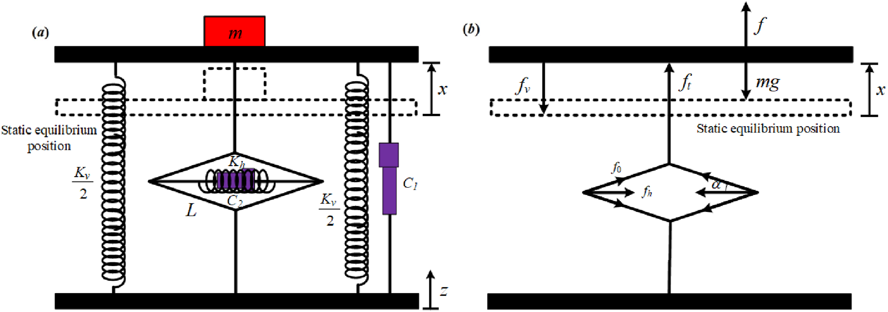
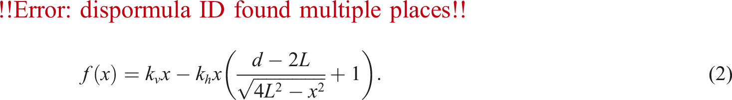
Notably, the restoring force in the system will be equal in size but opposite in direction to the applied force. The equation presented below describes how the applied force is related to the resulting displacement

The regulating load’s equation under the impact of harmonic force is given as
36


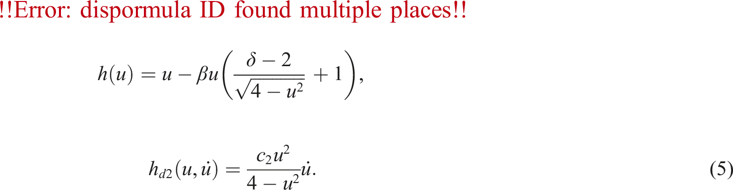
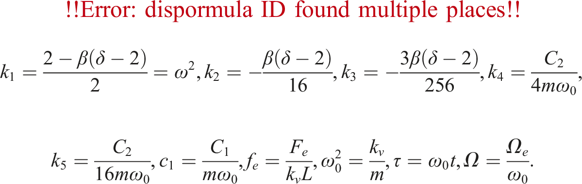
It is possible to convert equations (2) and (4) into a dimensionless form

Using the Taylor series till the third approximation of (5) and the non-dimensional parameters (6), the equation of motion (3) will be

At this stage, we are going to establish the QZSVI mathematical model, focusing on the impact of NDFC, NVFC, and NCVFC on the response cases for reducing induced vibrations, as shown in Figure 2. Given these considerations, the mathematical model for the QZSVI system will be constructed as follows NDVFC, NVFC, and NCVFC of the dynamical model.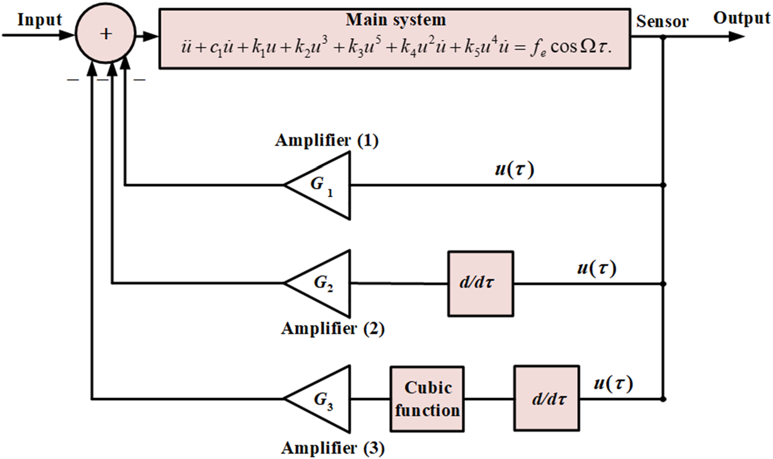

The recommended methodology
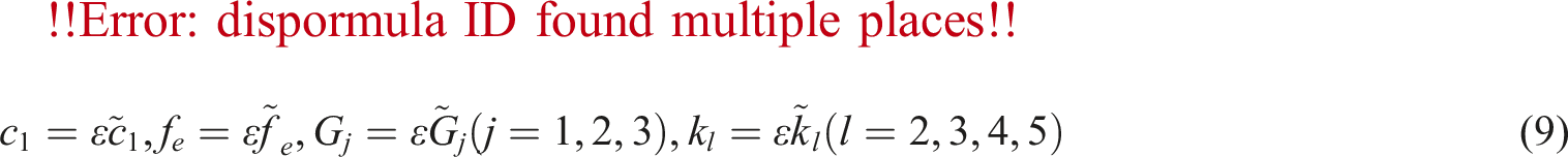
The asymptotic analytic solutions to equation (8) are obtained in the present section by means of the MSP. Consequently, we direct our study toward the system’s dynamic behavior within a limited region bounded by the static equilibrium position. Following this, the smallness of the parameters and variables was incorporated, in line with
As stated by the MSP, the solution

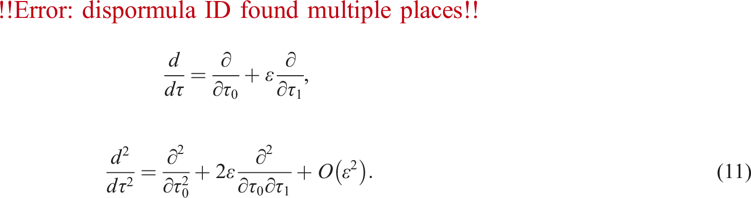
These operators clearly show that terms
(a) Order

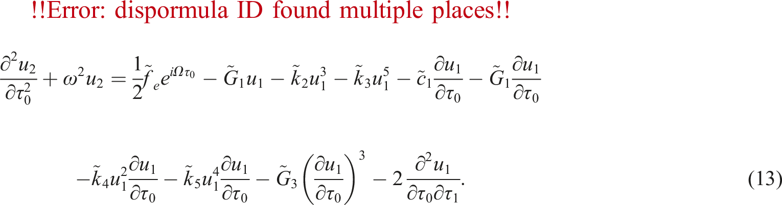
(b) Order of
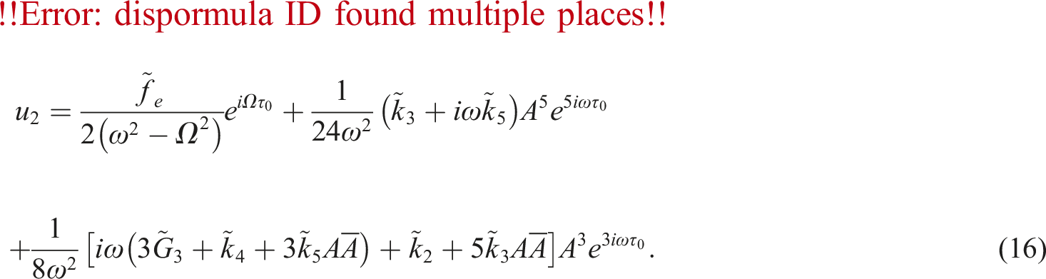
Therefore, the general solution of (12) can be obtained as follows

Eventually, we obtained the second-order solution, which is presented below
Resonance classification and modulation equations
This section’s goals are to categorize the different resonance cases, address one of those situations, and obtain the ME. If any of the denominators in the final solution approaches disappear, such conditions could appear.
32
Consequently, opportunities that follow occur • Primary external resonance case can be found at • Internal resonance case at
If any of the resonance requirements outlined earlier are satisfied, the system will show intricate and complicated behavior. It’s important to keep in mind that even when the vibrations go away from resonance, the solutions obtained are still appropriate. Let’s now investigate the issue more closely and look at the main external resonance that happened at

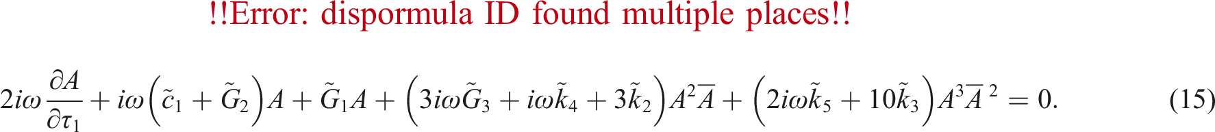
Two nonlinear partial DEs with regard to

The operator of the first-order derivative can be written in the following manner because the functions

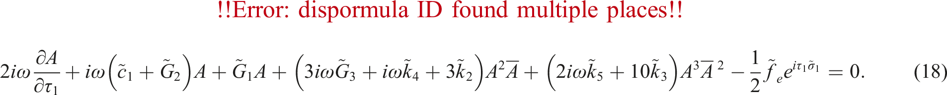
In dependence on (20), the subsequent modified phase can be utilized to convert the solvability criteria of partial DE (18) into ordinary ones as

By substituting (19)–(21) into (18) and dividing the imaginary and real components, the system below can be achieved based on the previous
Steady-state approach and stability analysis
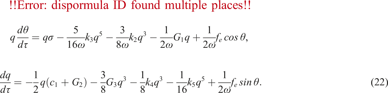
The solutions for the dynamical system’s steady-state condition are the main topic of this section. In this scenario, the solutions would show up at the conclusion of the temporary procedures. In this case, we take into consideration the zero value of
After the modified phase
The stability behavior of these solutions is discussed by linearizing (22) using the Lyapunov first (indirect) approach, which yields the following system
8
Consequently, the ability to analyze and solve the characteristic equation determines the steady-state solution’s stability. The Jacobian matrix’s eigenvalues may be written in the following manner
9


By using the Routh–Hurwitz criterion,
33
we can observe that the state’s solution is asymptotically stable if and only if all real portions for the roots of (28) are negative. This condition occurs if the coefficients fulfill

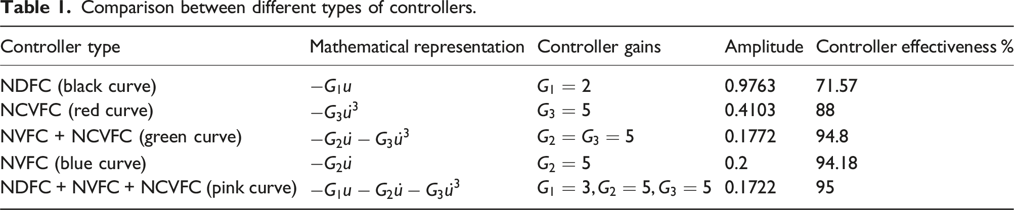
Results and discussion
This section illustrates the system’s performance in terms of amplitude and phase, examining both controlled and uncontrolled cases, including the resonance condition. We compare different control systems and analyze how specific parameters influence system amplitude. Additionally, we explore the relationship between system amplitude and the detuning parameter
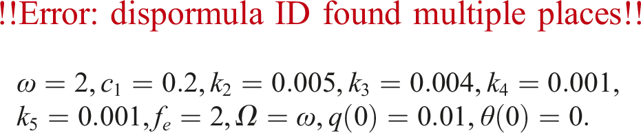
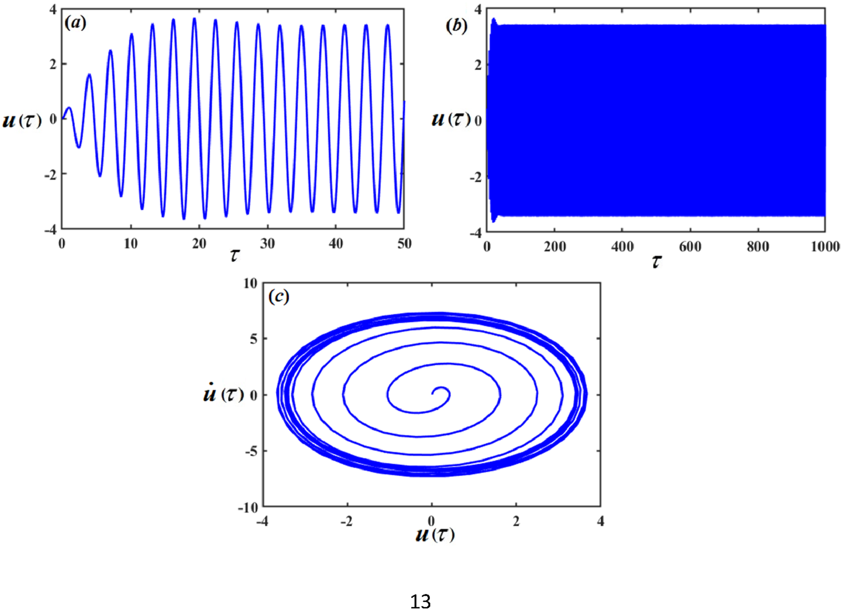
Figures 3(a) and (b) show the time history of the function Time response solution The time response solution The time response solution Comparison between different types of controllers.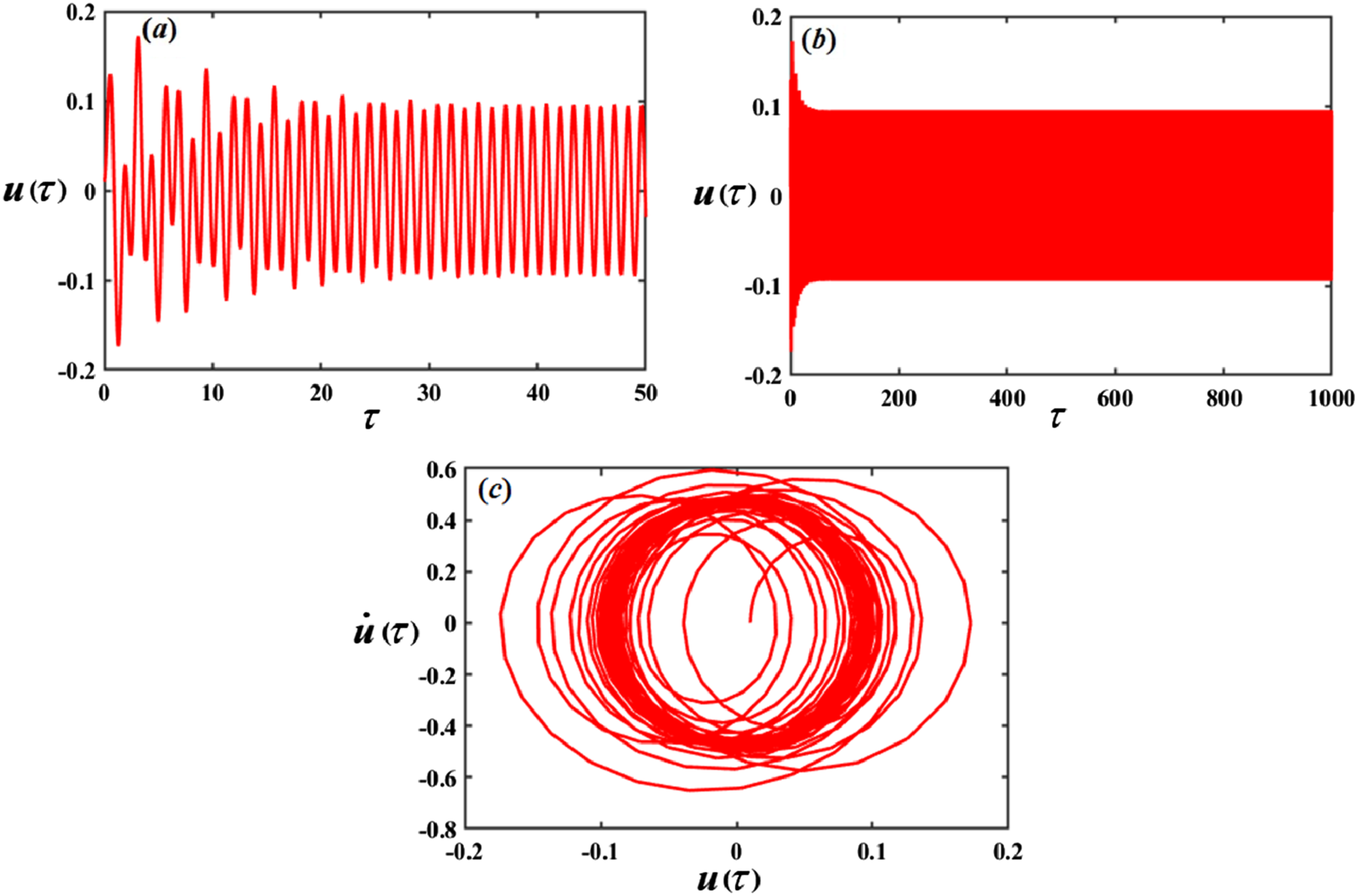
The curves in Figures 6(a) and (b) compare the analytic solution induced by MSP and the numerical solution using RKM at resonance case without control for short and long time intervals, respectively. On the other hand, the comparison of the AS and the NS for the resonance case with control (NVFC + NCVFC) is depicted in Figure 7 in two different time ranges. The comparisons between the analytical and numerical solutions demonstrate considerable agreement. The comparison between NS, represented by the red line, and AS, represented by the blue line, in resonance case The comparison between NS, represented by the red curve, and AS, shown by the blue curve in the resonance case 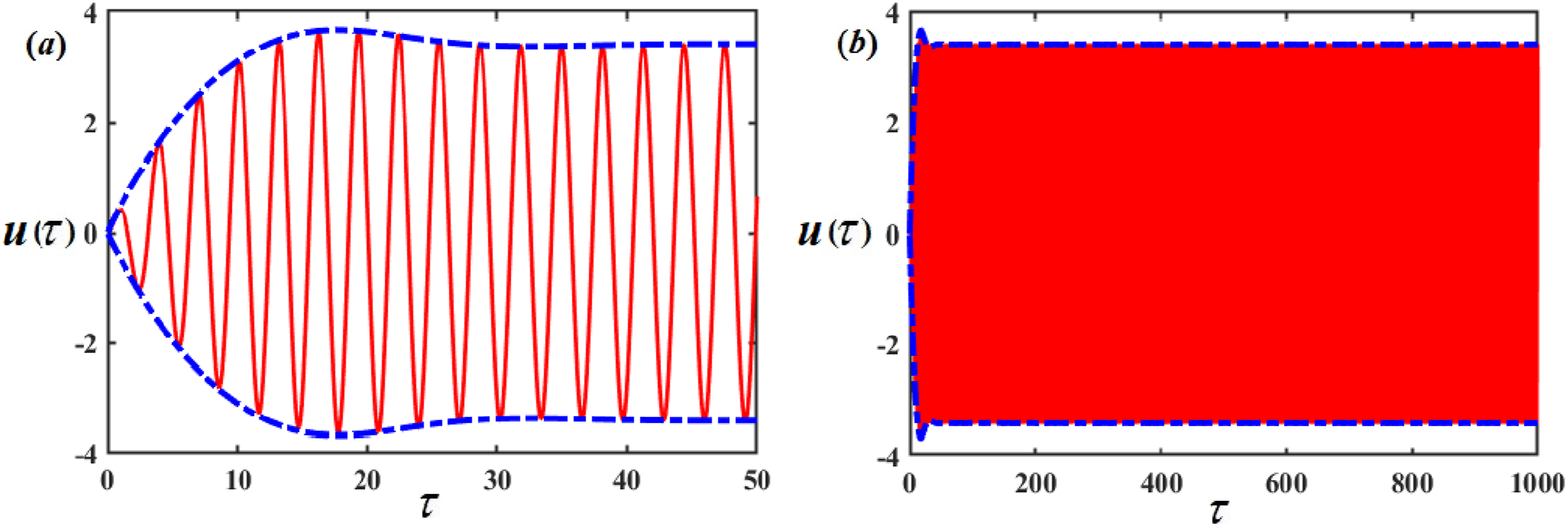
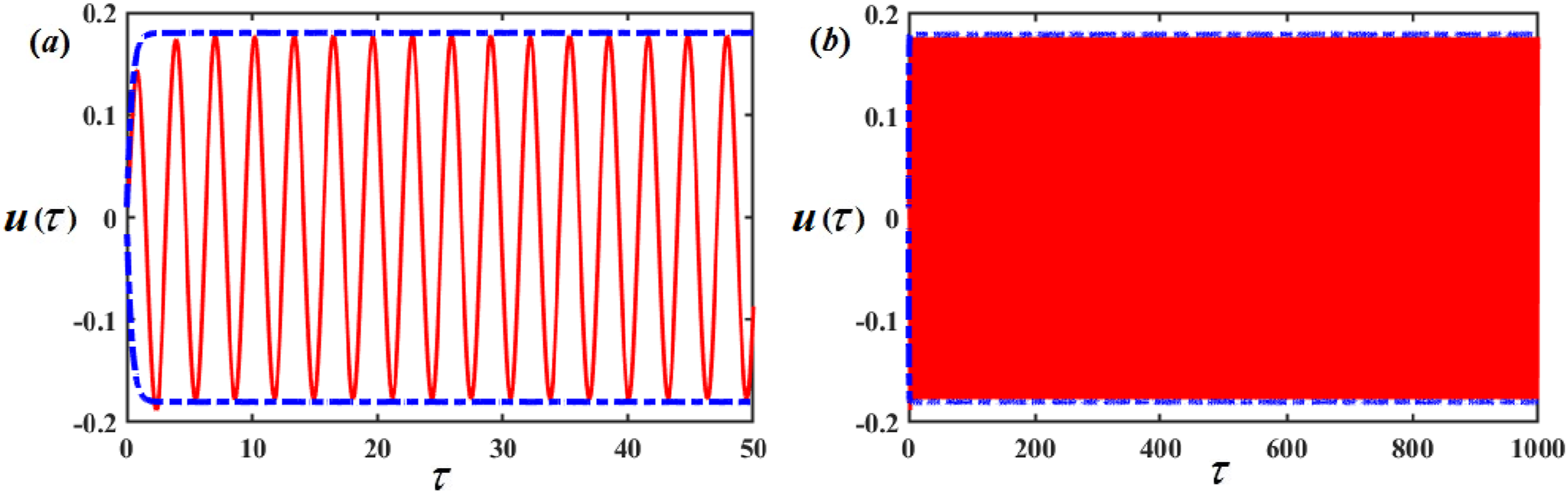
Let us demonstrate the amplitude changes of System parameter effects 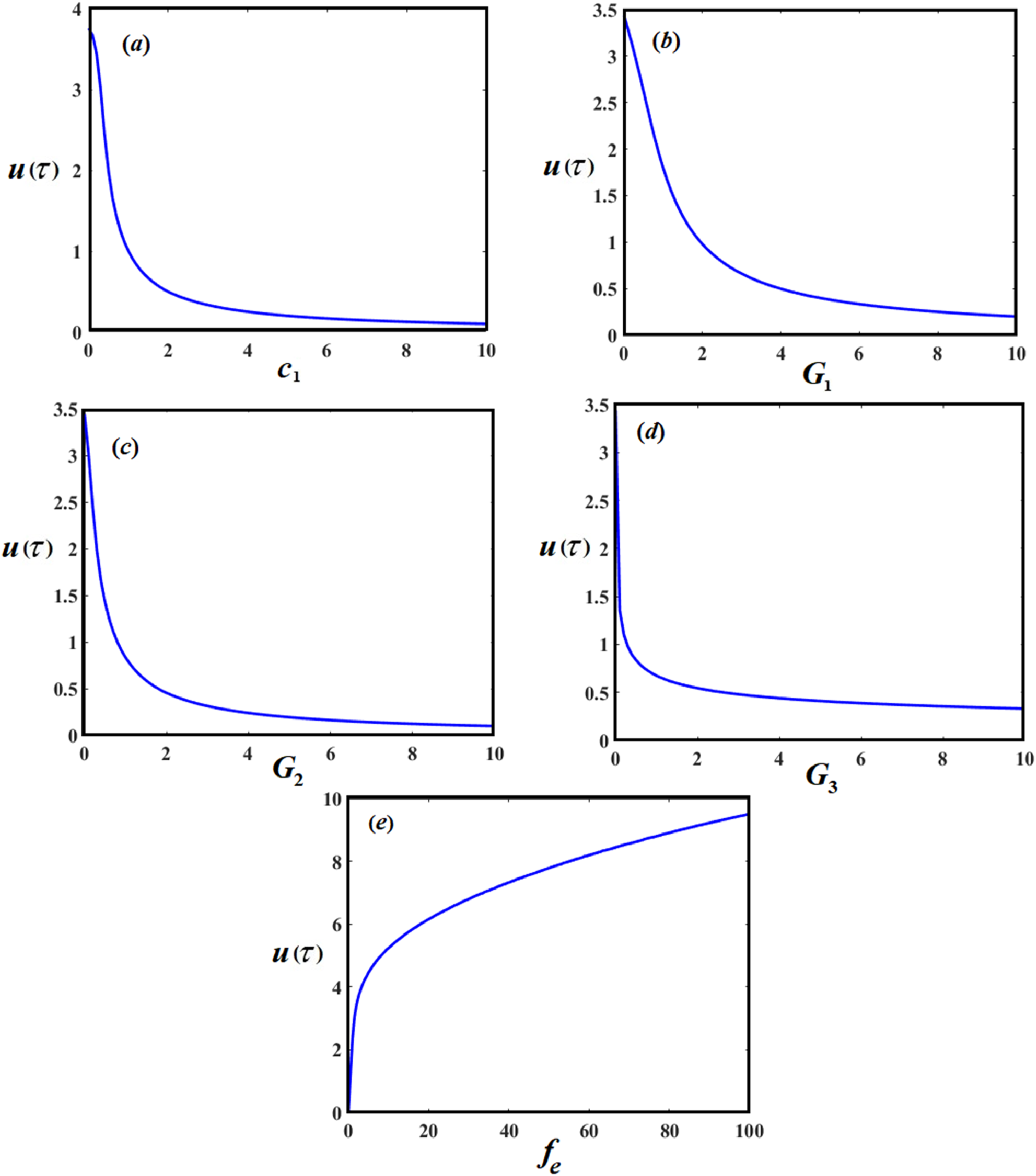
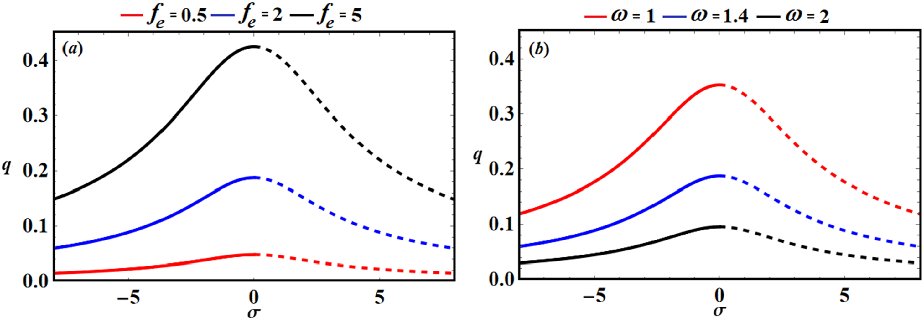
The fixed points’ stability regions, explored in Figures 9 and 10 will be presented using the resonant response curves produced from the NS of equation (24). It’s important to keep in mind that solid lines indicate stable fixed points, whereas dashed ones illustrate unstable ones. It was shown that some stability criterion parameters have a substantial impact on stability analysis, such as gains of controllers Amplitude’s resonance curve Amplitude’s resonance curve 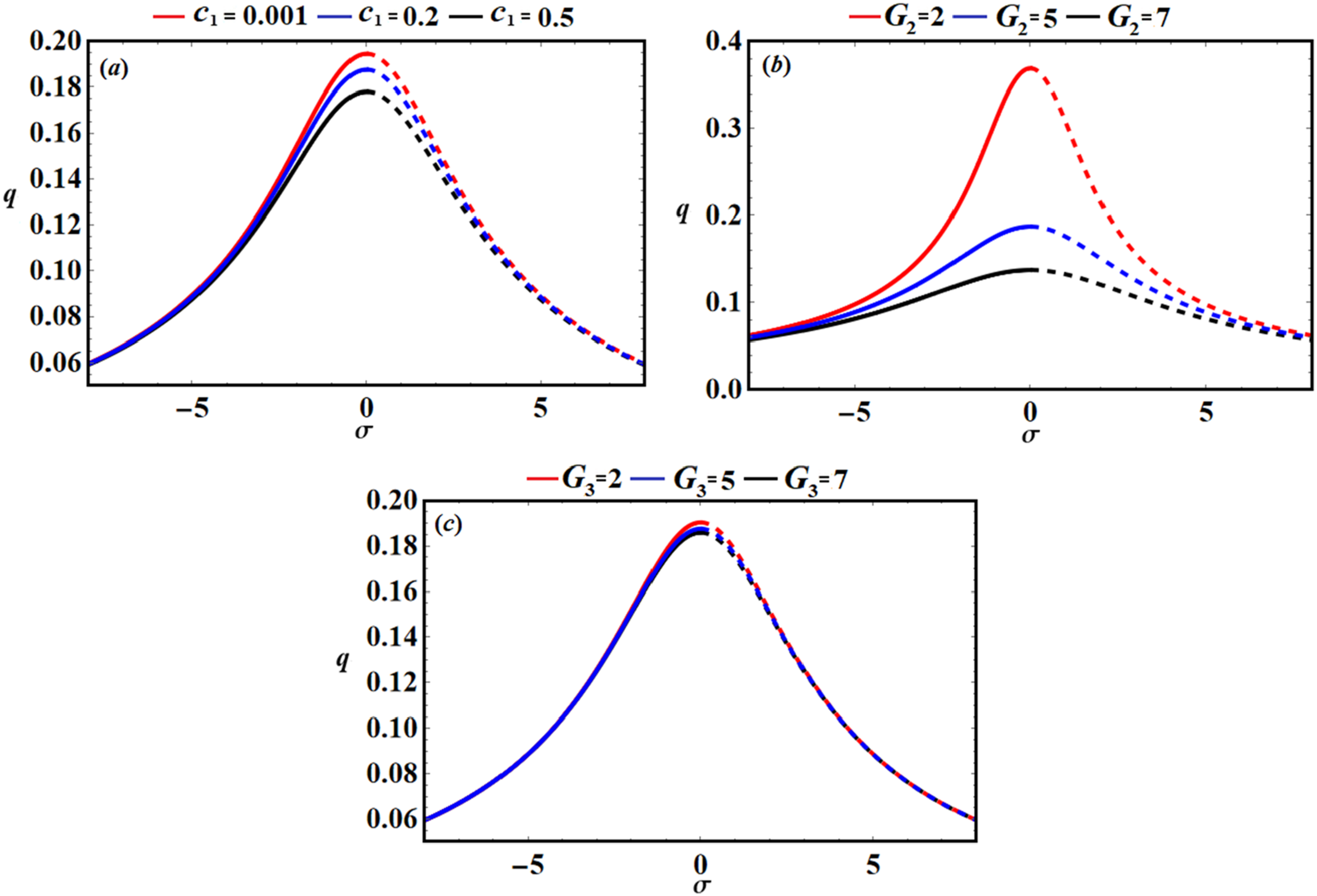
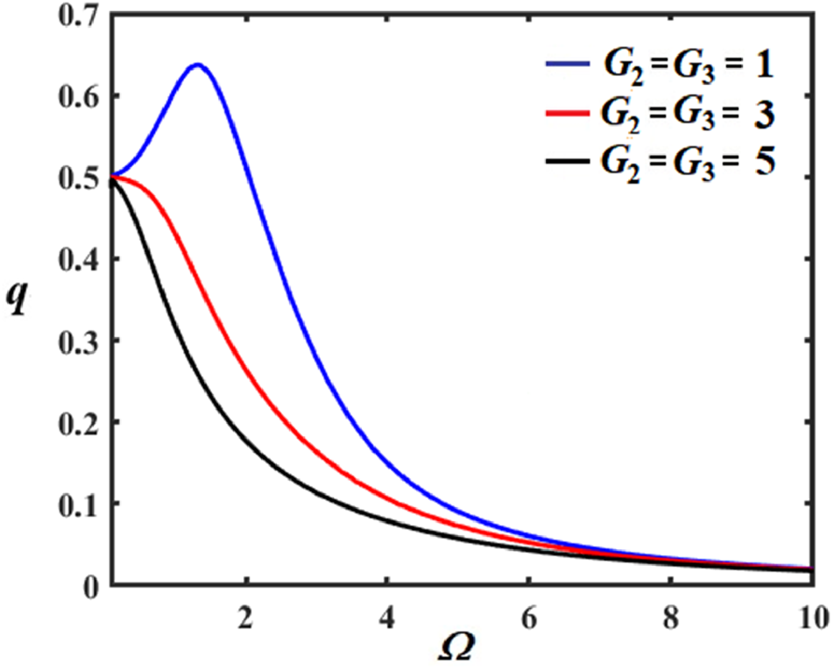
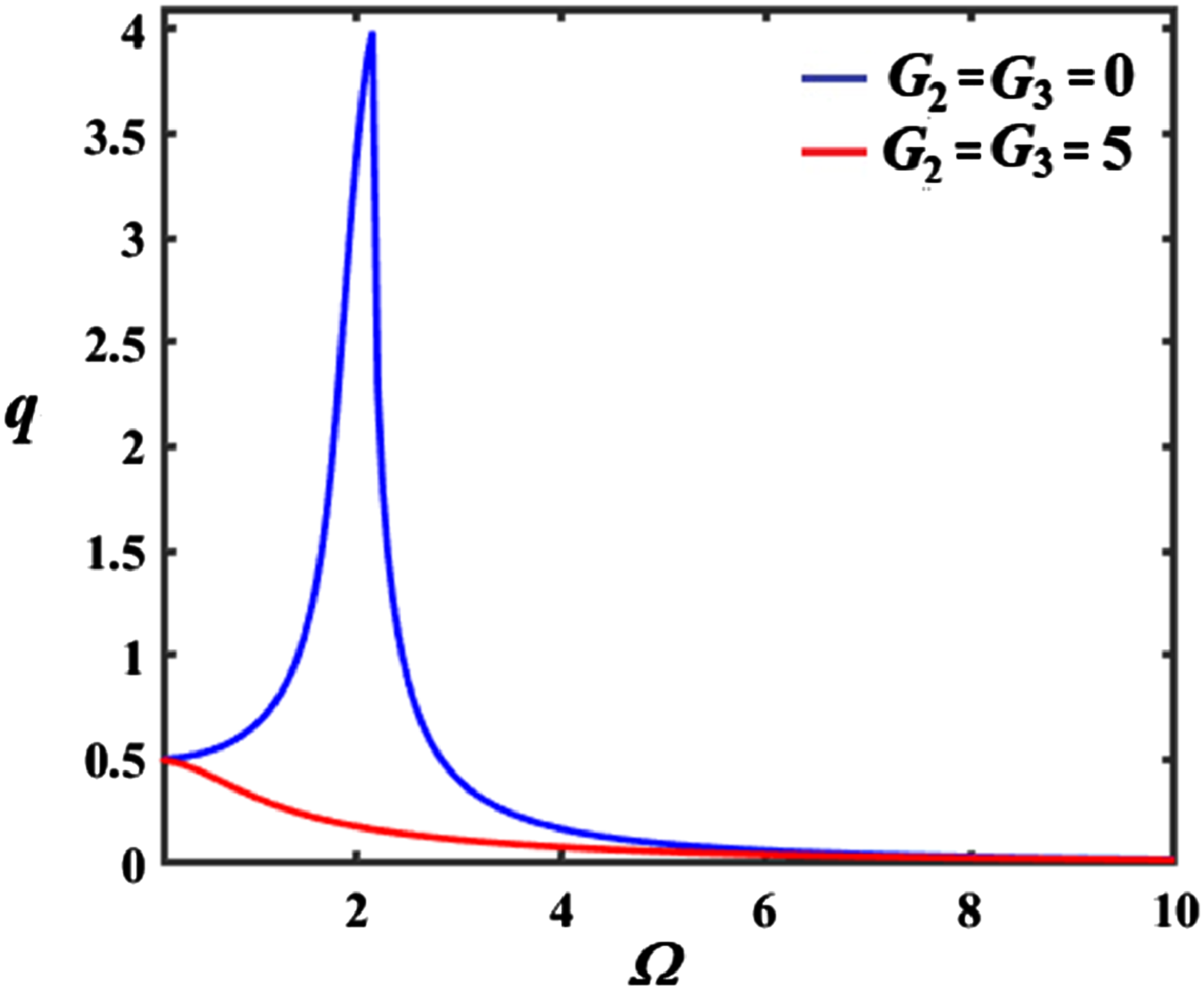
The frequency response curve of a dynamical system shows how the system’s amplitude response changes with the range of excitation frequency. Figure 11 illustrates the amplitude-frequency response of QZSVI without control Amplitude–frequency curve Amplitude–frequency curve Amplitude–frequency curve 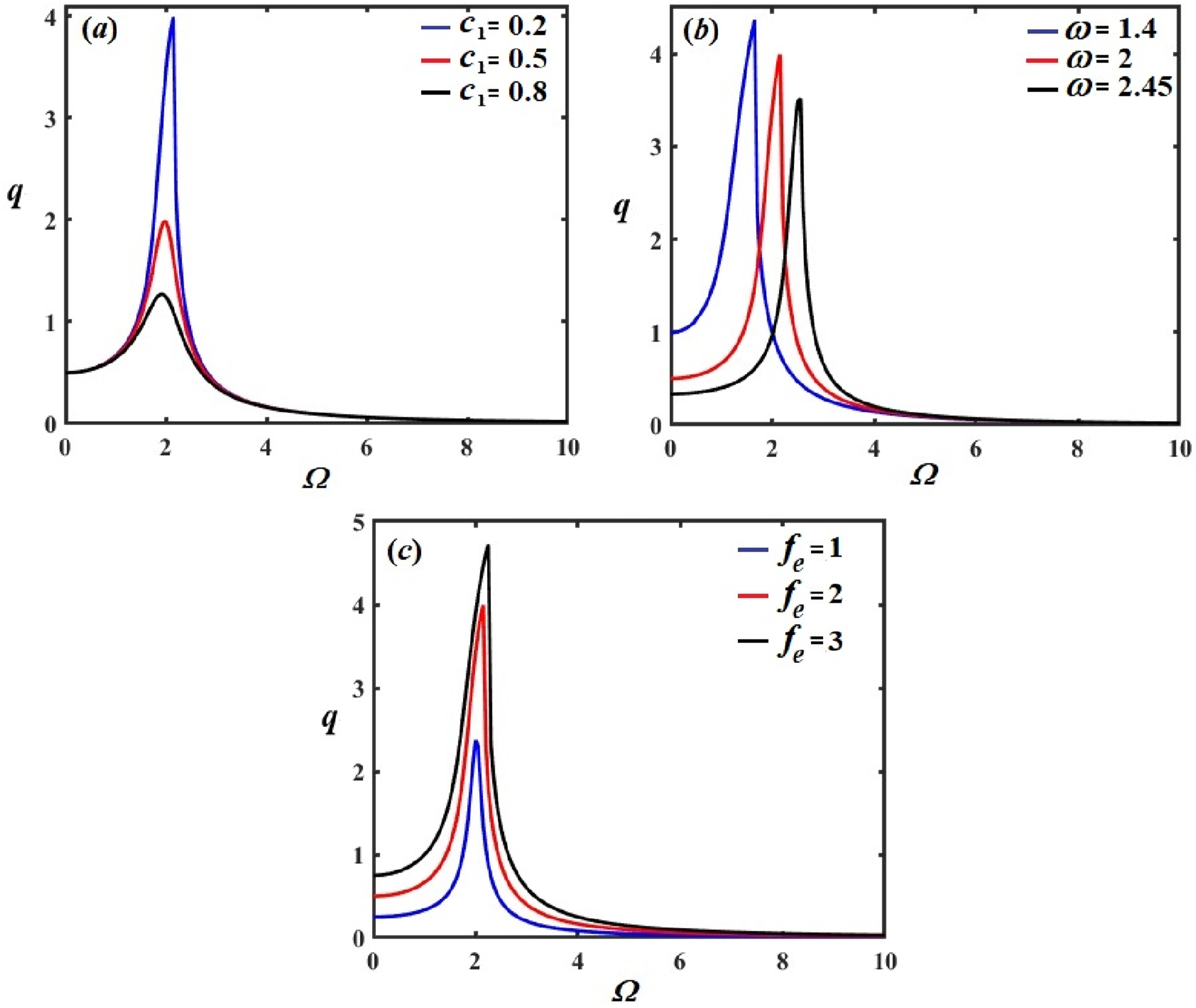
The system’s behavior, as a parameter varies, is shown graphically by bifurcation curves. They identify transitional phases in the behavior of the system, such as the emergence of new equilibrium points or periodic orbits. Conversely, Lyapunov analysis assesses the stability of the dynamical model through the investigation of the solutions that are in close proximity to it. To ascertain whether little deviations from an equilibrium point result in overtime convergence or divergence, Lyapunov functions are employed. In order to forecast and comprehend complicated phenomena like chaos or stability transitions, bifurcation curves and Lyapunov analysis work together to shed light on the behavior and stability of dynamic systems.37–39 To display the different forms of motion, bifurcation diagrams of Bifurcation diagram, LEs with the damping coefficient Bifurcation diagram, LEs with the damping coefficient Bifurcation diagram, LEs with the damping coefficient 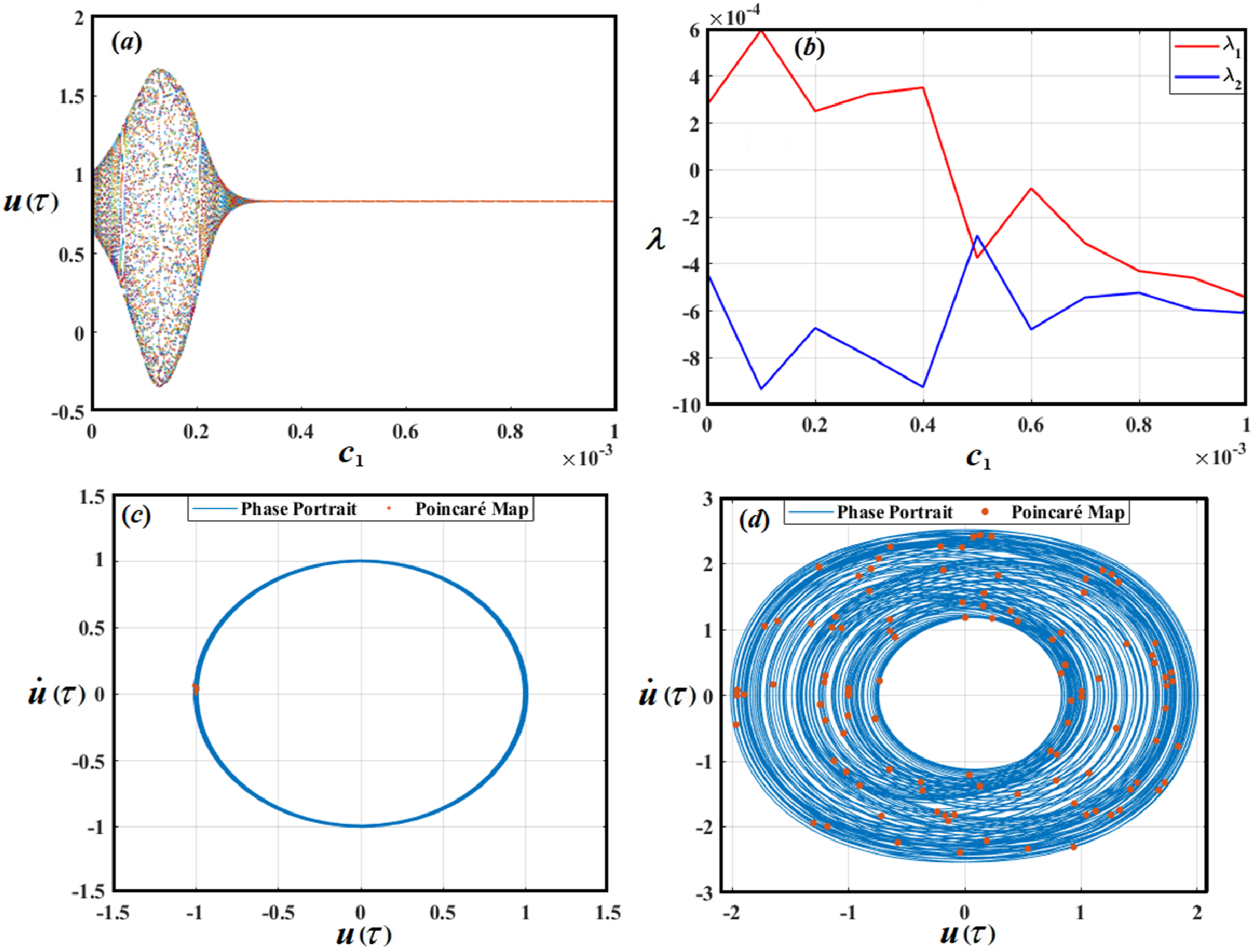
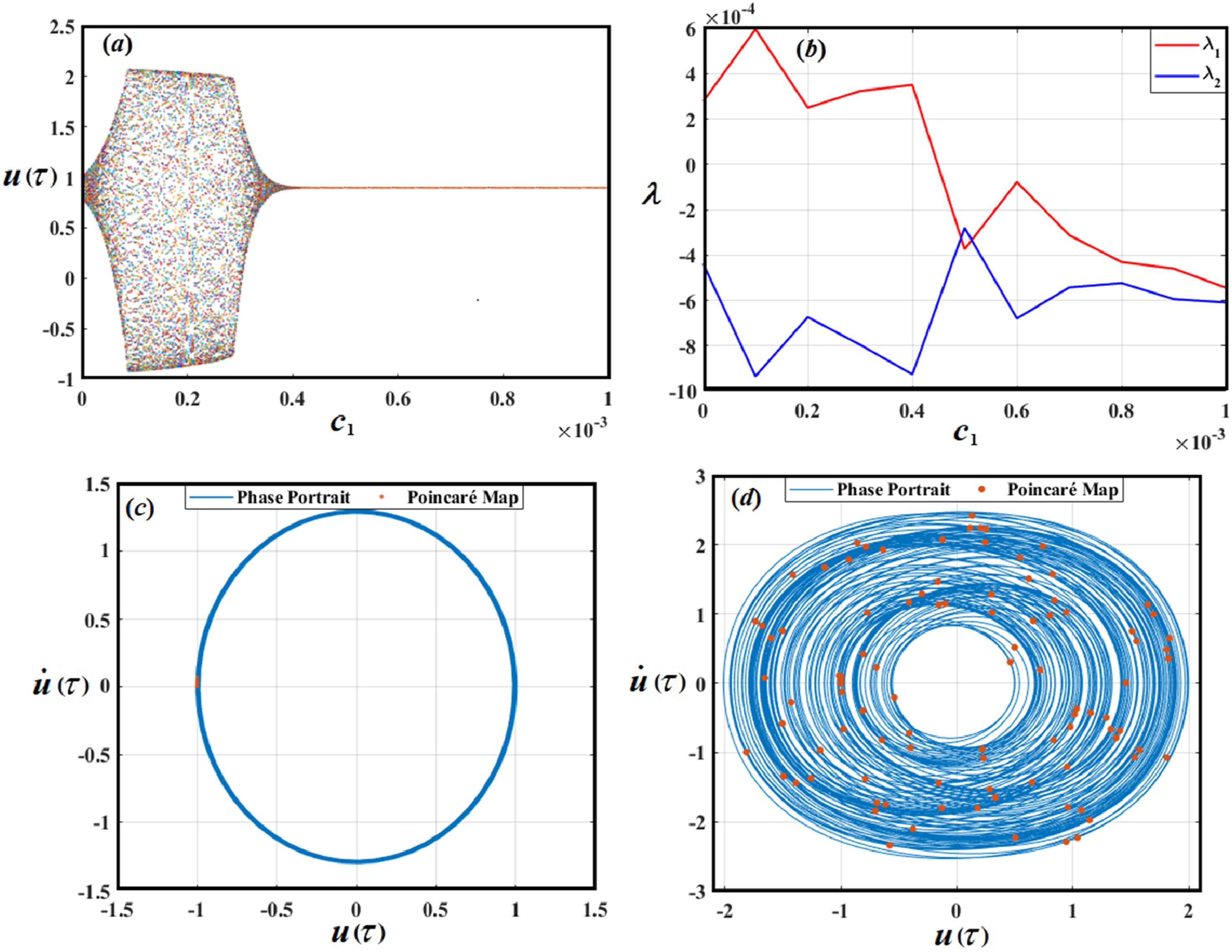
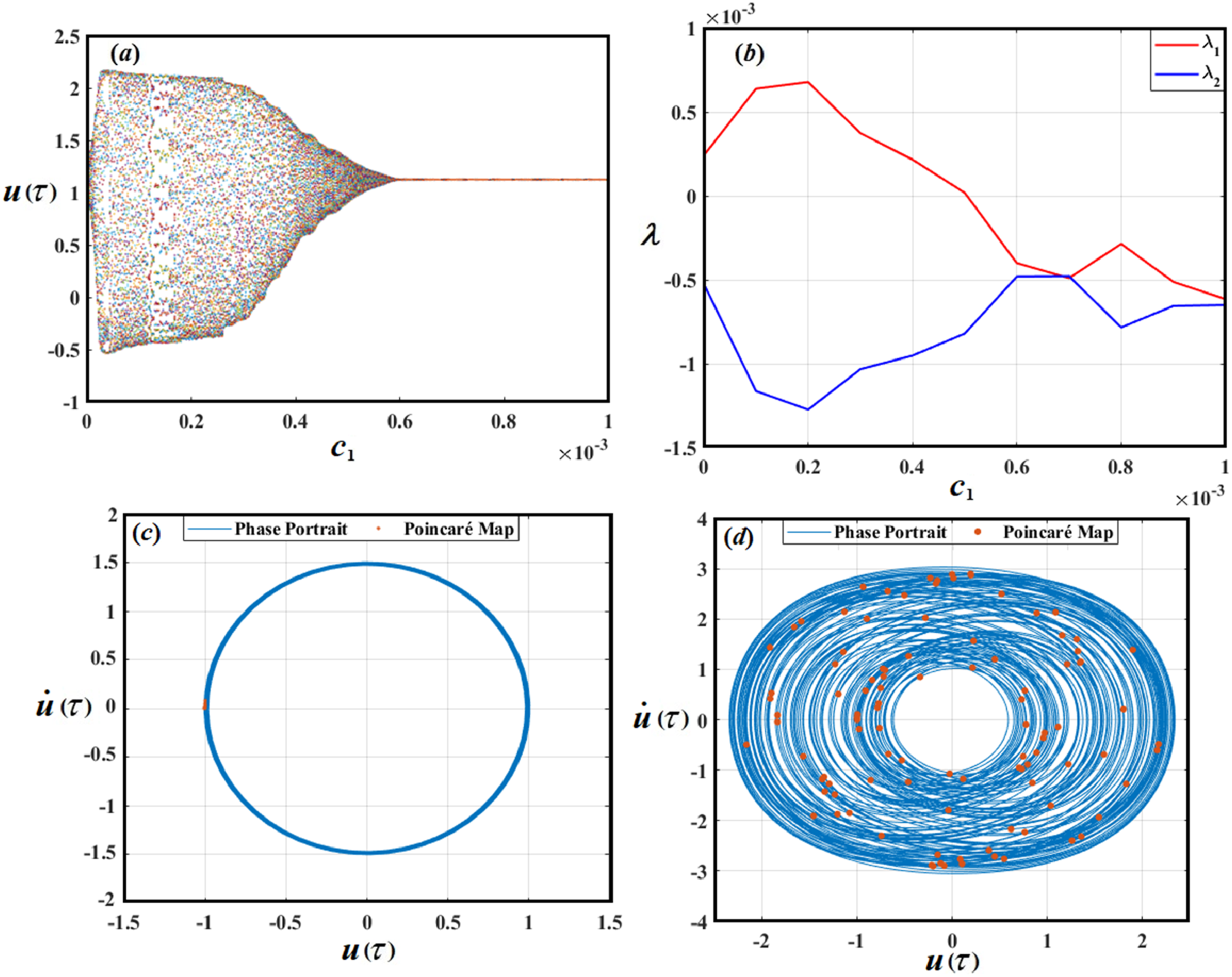
Diagrams in Figure 14 at
The phase portraits and Poincaré maps
10
are simulated in Figures 14(c) and (d)–16(c) and (d), in which blue curves illustrate the phase portraits while the red dots represent the Poincaré maps. The generated figures were displayed for several values of the damping coefficient
To emphasize the importance of the presence of feedback control in this system, bifurcation diagrams of Bifurcation diagram, LEs with the damping coefficient 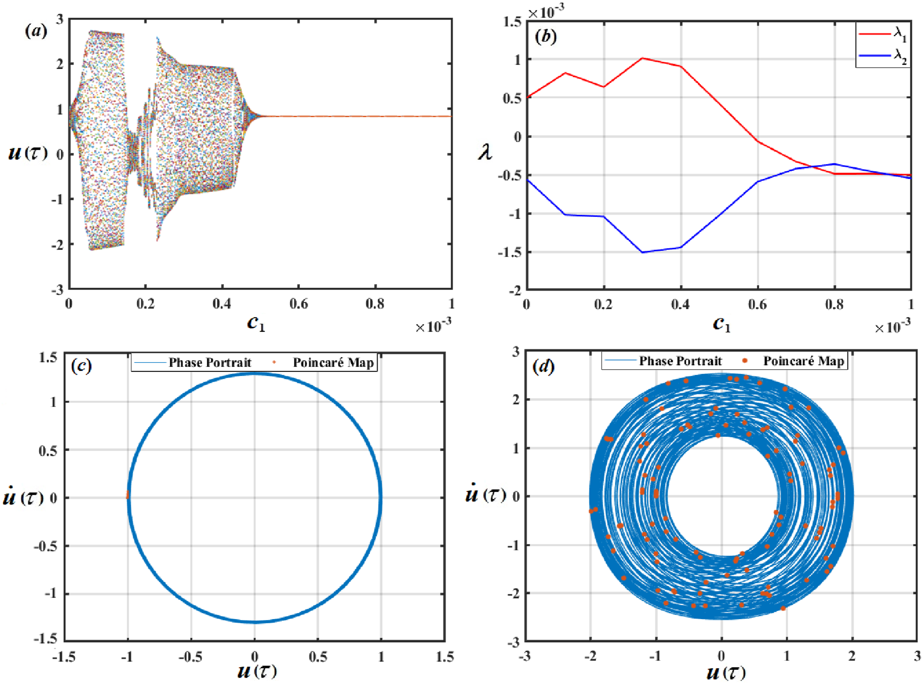
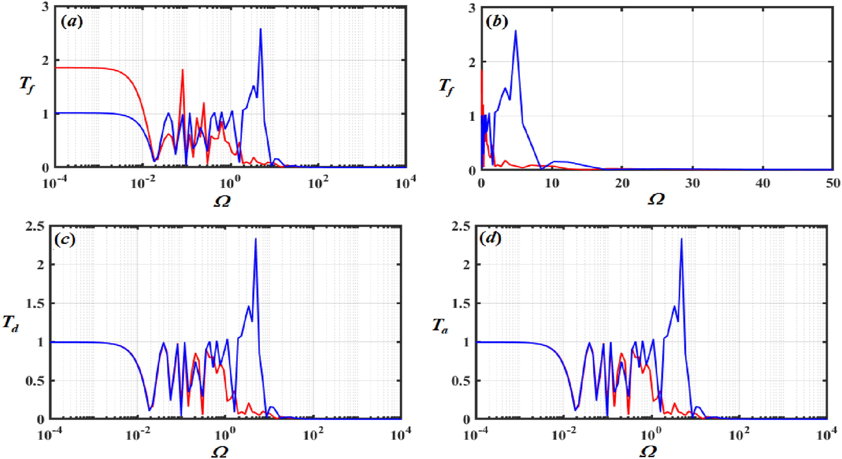
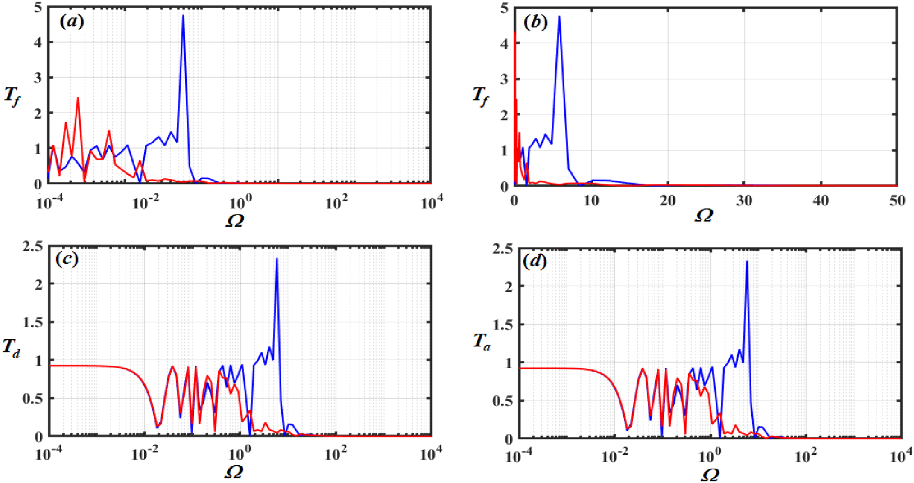
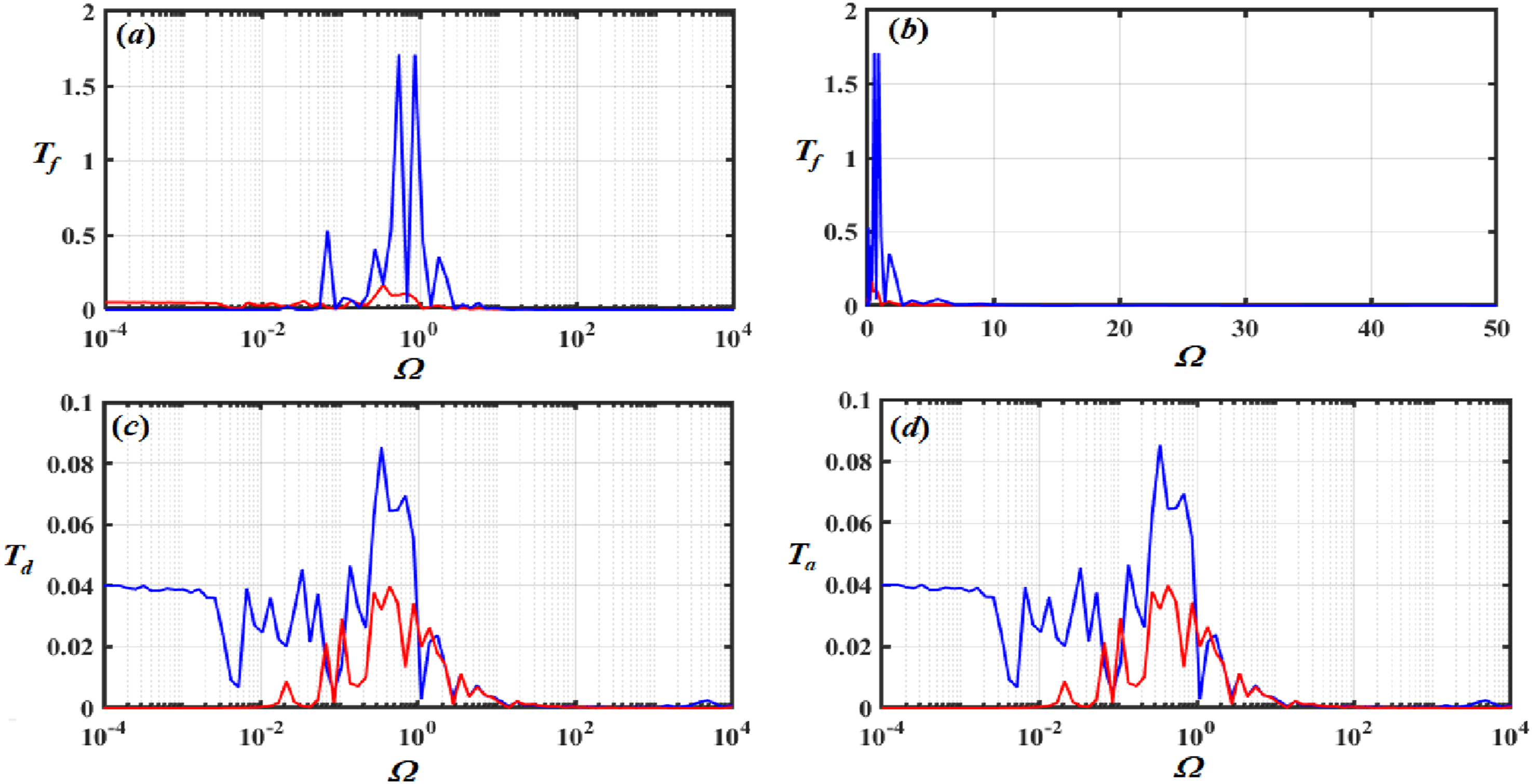
Force, displacement, and acceleration transmissibility
In vibration analysis, force, displacement, and acceleration transmissibility are essential ideas that explain the transmission of vibratory energy throughout a system.
36
The amount of vibrating force that flows through a structure is indicated by its force transmissibility (
Assume that


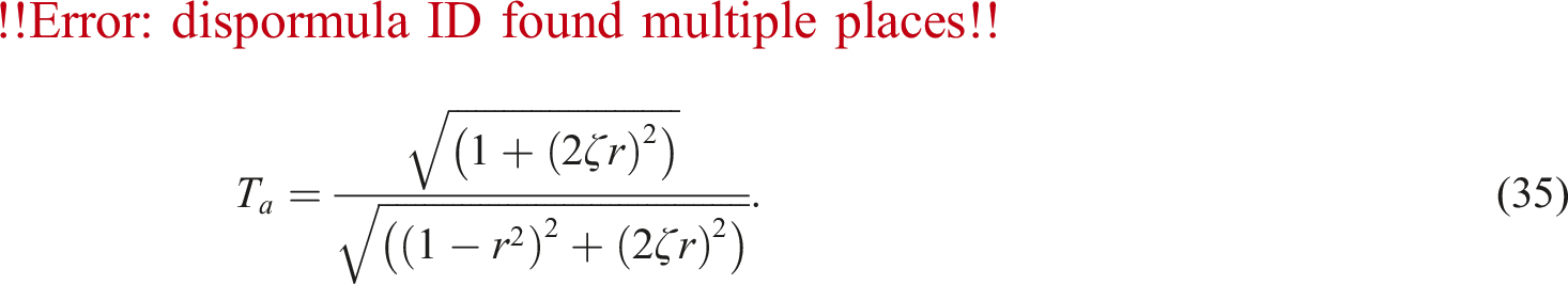

Figures 18–21 show the force, displacement, and acceleration transmissibility without control (blue line) and with control (red line) Force, displacement, and acceleration transmissibility without control (blue line) and with control (red line) Force, displacement, and acceleration transmissibility without control (blue line) and with control (red line) Force, displacement, and acceleration transmissibility without control (blue line) and with control (red line) Force, displacement, and acceleration transmissibility without control (blue line) and with control (red line) 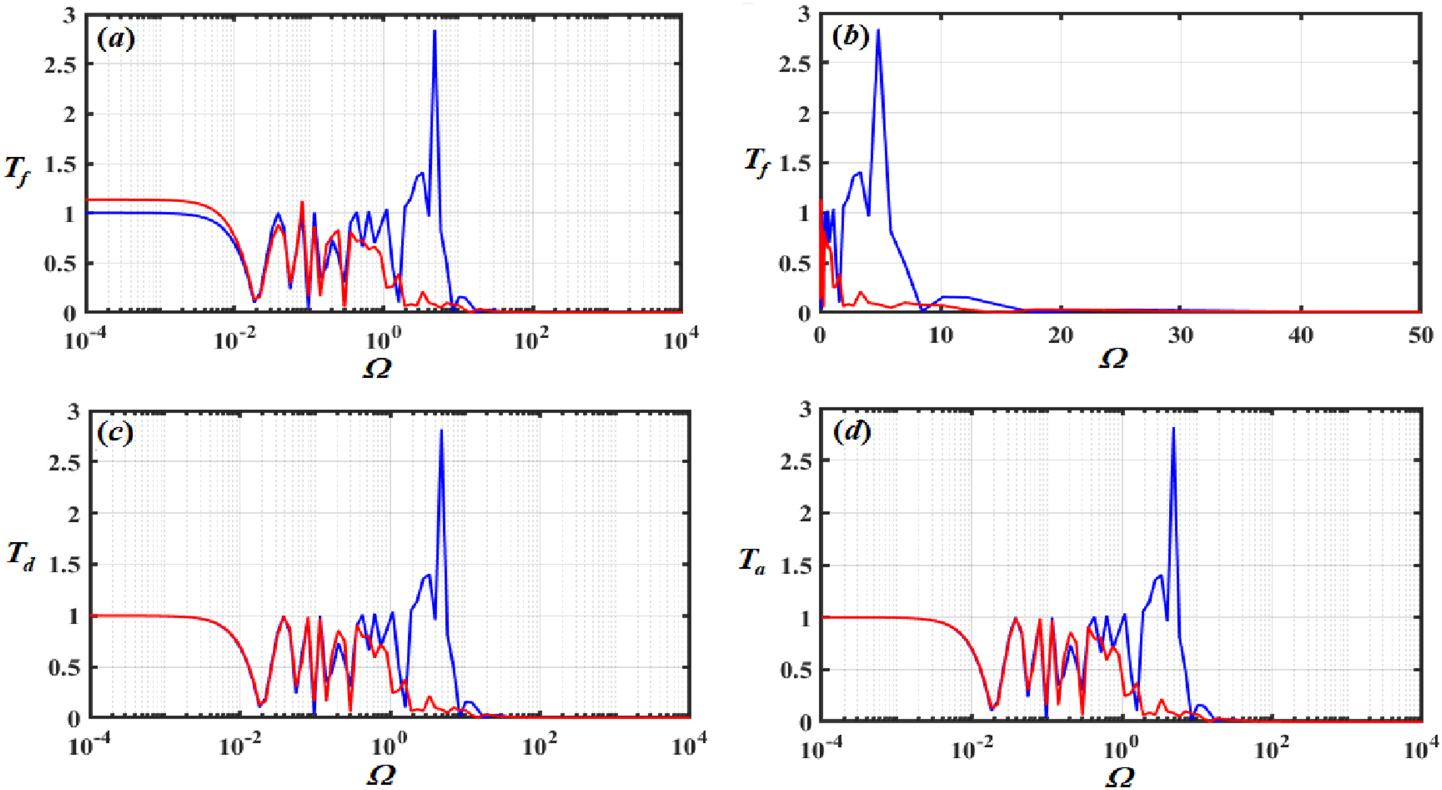
Conclusion
The isolation performance of a QZSVI system can be improved by using the NDFC, NVFC, NCVFC, NVFC + NCVFC, and composite controllers NDFC + NVFC + NCVFC approaches. Any potentially dangerous vibrations are reduced by using these controls. The AS of the system is obtained using a MSP up to the second order. It is then verified numerically by applying the RKM. The ME are acquired, and every case of established external resonance is assessed. The bifurcation plots, Poincaré maps, and LEs show and analyze two different motions of the system: periodic and chaotic motion. The resonance response curves show the locations of the system’s stable and unstable fixed points. It was discovered that as a result of the NDFC, NVFC, NCVFC, NVFC + NCVFC, and composite controllers NDFC + NVFC + NCVFC, the amplitude of
Footnotes
Author contributions
Taher A. Bahnasy: Supervision, Investigation, Methodology, Corroboration, Validation, Data duration, Examination, Visualization and Reviewing. T. S. Amer: Supervision, Resources, Conceptualization, Formal analysis, Methodology, Validation, Reviewing and Editing. A. Almahalawy: Conceptualization, Supervision, Validation, Corroboration, Examination, Visualization and Reviewing. M. K. Abohamer: Conceptualization, Methodology, Validation, Examination, Corroboration, Visualization and Reviewing. H. F. Abosheiaha: Supervision, Formal analysis, Examination, Data duration. A. S. Elameer: Formal analysis, Investigation, Methodology, Writing-Original draft preparation, Visualization, and Reviewing.
Declaration of conflicting interests
The author(s) declared no potential conflicts of interest with respect to the research, authorship, and/or publication of this article.
Funding
The author(s) received no financial support for the research, authorship, and/or publication of this article.