This paper investigates stability of the synchronous states for three homodromy exciters in the vibrating system, some theoretical analyses and simulation results on which are given. Based on Lagrange equations, the differential equations of motion of the system are obtained. Using the average method yields the dimensionless coupling torque balanced equations of three exciters and the simplified analytical expressions for synchronization criterion of the system are deduced, the stability criterion of the synchronous states complies with Routh–Hurwitz principle. The dynamic characteristics of the system for different frequency ratios are discussed numerically. In order to verify the validity of theoretical methods, the simulation results by a Runge–Kutta routine are carried out; it indicates that the motion state of the vibrating system can be classified into two types: sub-resonant state and super-resonant state. The motion type of the rigid frame is strong positive superposition vibration in a sub-resonant state; while in a super-resonant state, the exciting forces of three exciters are mutually cancelled and the rigid frame is motionless. During the design process of the vibrating machines, the ideal working points are only selected in a sub-resonant state, which makes the vibrating machines work efficiently.
As a common phenomenon in nature, synchronization contains enormous research values. The so-called synchronization, which means that two or more objects achieve the same or similar physical form, such as the same velocity, the same phase, the same or similar motion trajectory, etc. In recent years, the researches about synchronization have mainly involved the fields of physics, biology, chemistry and society, such as complex network, couplings pendulum, mechanical oscillators, electromechanical devices, and so on.1–5 In Yamapi and Woafo6 “the synchronized integral” method is developed for positioning the measurement microphones. Vibratory synchronization is an important field of synchronization study, the researches on which have been developing in deep. The earliest detailed records about synchronization were conducted by Huygens.7 Following, Rayleigh8 found that two organ pipes could produce synchronized sounds when two air vents were approached, and Van der Pol9 observed synchronous phenomena in nonlinear circuits. In the 1960s, Blekhman and co-workers10–13 first explained the synchronization problem of two identical exciters from the point of view of its theory. Wen et al.14,15 applied such theory to engineering and also developed it to a certain extent. Besides, Balthazar et al.16,17 gave some reviews on the self-synchronization of two and four nonideal exciters by numerical simulations. The dynamic controls of synchronization for exciters were proposed by Nijmeijer18 and Fradkov and Andrievsky.19
Vibratory synchronization brings inconvenience or harm to people in a certain way. For example, when the vibrating machines operate synchronously, the structures of machines may be damaged, that is the common resonance in engineering, which can make the working efficiency greatly be affected. We can, therefore, take some measures to control vibration, for instance using 1:1 internal resonance absorber implements the nonlinear vibration control for flexible manipulator.20 But in other respects, vibratory synchronization can also be beneficial to people’s life, such as the launch and reception of the broadcast signal; the receiver can only receive this broadcast signal when the receiving frequency and transmitting frequency are consistent. The researches of vibratory synchronization are developing rapidly,which have facilitated the presentation of many new theory analysis methods and the extension of their application fields.
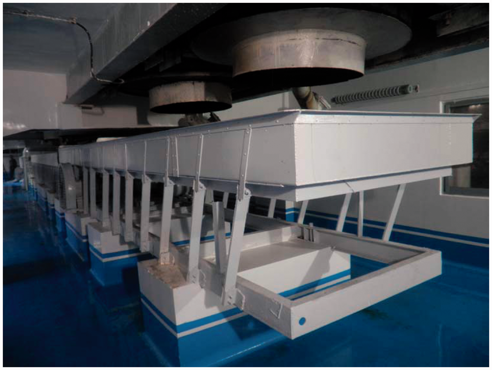
In vibration utilization engineering, vibratory synchronization theory is widely applied to many industries, such as self-synchronous vibrating crusher, screen classifier, conveyor, and so on. Figure 1 shows the long-distance vibrating conveyor with single- or dual-motor drive in a sub-resonate state. However, for the more long-distance vibrating conveyor desired in engineering, the driving power is limited and considering the uniformity of the exciting forces distribution, single- or dual-motor self-synchronous driving no longer meets the above requirements, only more than two exciters can be utilized for self-synchronous driving. Therefore, the study of synchronization theory for single rigid frame driven by three exciters is of great significance. Using three motors can not only overcome the problem of insufficient power, but also make the distribution of exciting forces be more uniform. Additionally, such vibrating conveyors have the advantages of compact structure, easy maintenance, low failure rate and strong stability.
Long-distance vibrating conveyor in a sub-resonant state.
The studying methods of synchronization theory for exciters are generally the method of direct motion separation proposed by Blekhman and co-workers10–13 and the averaging method of modified small parameters; based on the latter method, the synchronization problem of two or three vibrators rotating in the same (or opposite) directions for the far-resonant vibrating system has also been further studied.21–23 Stability of multiple exciters in the system with double resonant types, however, is less involved.
In the present work, taking a dynamical model with three homodromy exciters for example, stability of the synchronous states for three exciters in the vibrating system with double resonant types is given. The dynamic model and differential equations of motion of the system are shown in the next section. In the following, the criterions of synchronization and stability are derived. “Numeric analyses on the coupling dynamical characteristics” and “Computer simulations” sections are devoted to discussing the coupling dynamic characteristics and the simulation results, respectively. Finally, conclusions are presented.
Dynamic model and motion differential equations of the vibrating system
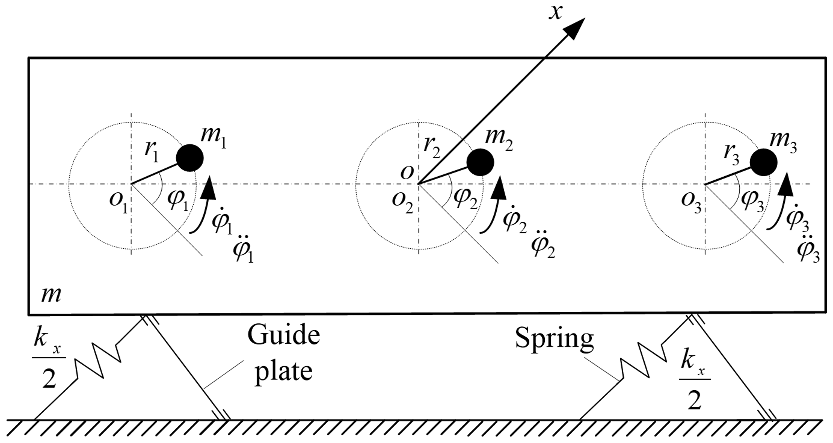
The dynamic model of a considered vibrating system is illustrated in Figure 2, which consists of a rigid frame and three exciters. The rigid frame is linked with the foundation by spring and guide plate, while three exciters are fixed on it. The center line of spring is parallel to the x-axis and vertical to the guide plate. Three exciters are driven separately by three induction motors rotating in the same direction, and their spin axes centers are , and , respectively. Additionally , and are collinear horizontally, , and are the rotational angles of three exciters, respectively. Due to the limitation of the guide plates, it can be supposed that the whole system displays the motion along with x-direction, and the displacement of the rigid frame is denoted by x.
Dynamic model of the vibrating system.
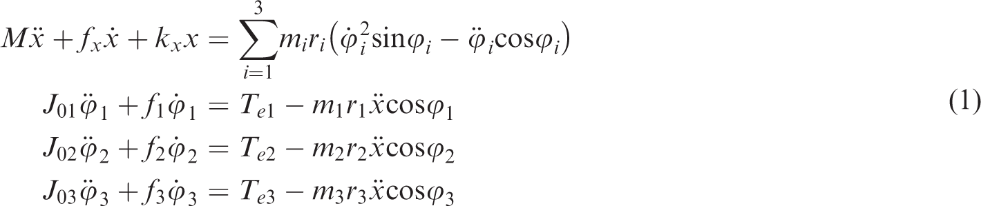
Based on Lagrange’s equation, the differential equations of motion of the vibrating system are derived as the following
where
Synchronization of three exciters and stability of the synchronous states
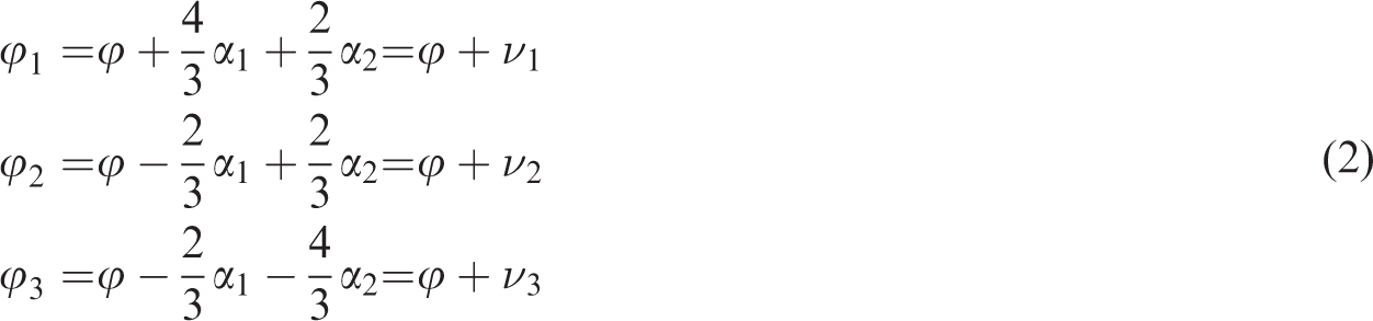
Assuming that the average phase of three exciters is , the phase differences among which are and , respectively, i.e., , , . Besides, the mass of the standard exciter is set as , then , and can be presented by , , , .
Hence
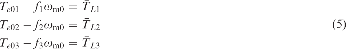
When three exciters operate synchronously, their synchronous angular velocity and the angular accelerations of three motors are approximately zero (i.e., ). Inserting equation (2) into the first formula of equation (1), it has
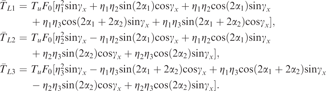
Differentiating equation (4) twice, inserting the result into the last three formulae of equation (1) and integrating them over , after the rearrangement, the balanced differential equations of three exciters can be obtained
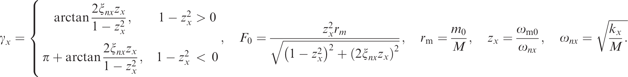
with
Here, is the kinetic energy of the standard exciter; the expressions of can be referred in Zhao et al.,24 and () is the output electromagnetic torque of the motor i.
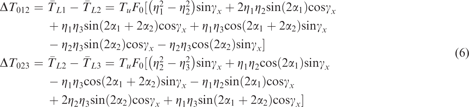
Based on equation (5), the difference of output electromagnetic torque between motors 1 and 2 and that between motors 2 and 3 are acquired, i.e.,
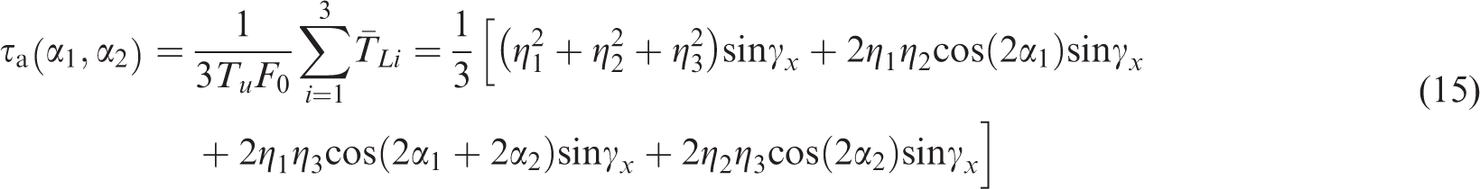
Here and are described as the dimensionless coupling torque between motors 1 and 2 and that between motors 2 and 3, respectively. The coupling dynamical characteristics of three exciters can be denoted as
Therefore, the synchronization criterion of three exciters is written in form
Equations (13) and (14) are conditions of implementing synchronization for three exciters, which can be described that the absolute values of dimensionless residual torque differences between arbitrary two motors should be less than or equal to the maximum of their dimensionless coupling torques.
Rearranging equation (5) by adding the whole formulae of it, we obtain
Here represents the average dimensionless loading torque of three motors, which is constraint function, i.e.,
In order to further analyze the synchronization ability of the system, the coefficients of synchronization ability are signified as follows
where
Generally, the larger the coefficients of synchronization abilities , and are, the stronger the synchronization abilities are, and the easier the system can implement synchronization.
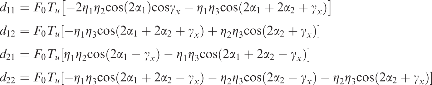
Exponential time dependence for the form is assumed and inserted into equation (24), solving the determinant equation det with respect to λ, the characteristic equation is easy to derive, i.e.,
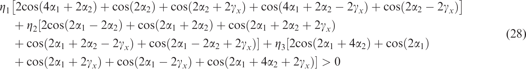
According to Routh–Hurwitz criterion,25 the zero solutions are stable if and only if all the roots in equation (25) have negative real parts. Therefore, the coefficients of characteristic equation need to meet the following requirements
are inserted into equation (26), the stability criterion of the synchronous states will be presented as
Numeric analyses on the coupling dynamical characteristics
This section will qualitatively give some numerical discussions based on the above theoretical results.
It is assumed that three motors are the same (three-phase squirrel cage, 380 V, 0.75 kW, 50 Hz, 6-pole, rated speed 980 r/min). Additionally, the intrinsic parameters of three motors are known: the stator resistance , the rotor resistance , the mutual inductance , the stator inductance , the rotor inductance , and . The other parameters of the system are , , , , .
Discussions on synchronization
As mentioned in “Synchronization criterion” section, and are limited functions of and , the curves of () versus for different are shown in Figure 3. We can see that the values of are the least near the resonance point (i.e., ), which indicates that the dimensionless coupling torques between arbitrary two motors are very small at this point. According to equation (17), the coefficient of synchronization ability is defined as the ratio between and , which is called the coefficient of the general dynamic symmetry (CGDS). Just as analyses above, the better the CGDS is, the stronger the ability to implement synchronization is.
Values of versus for different .
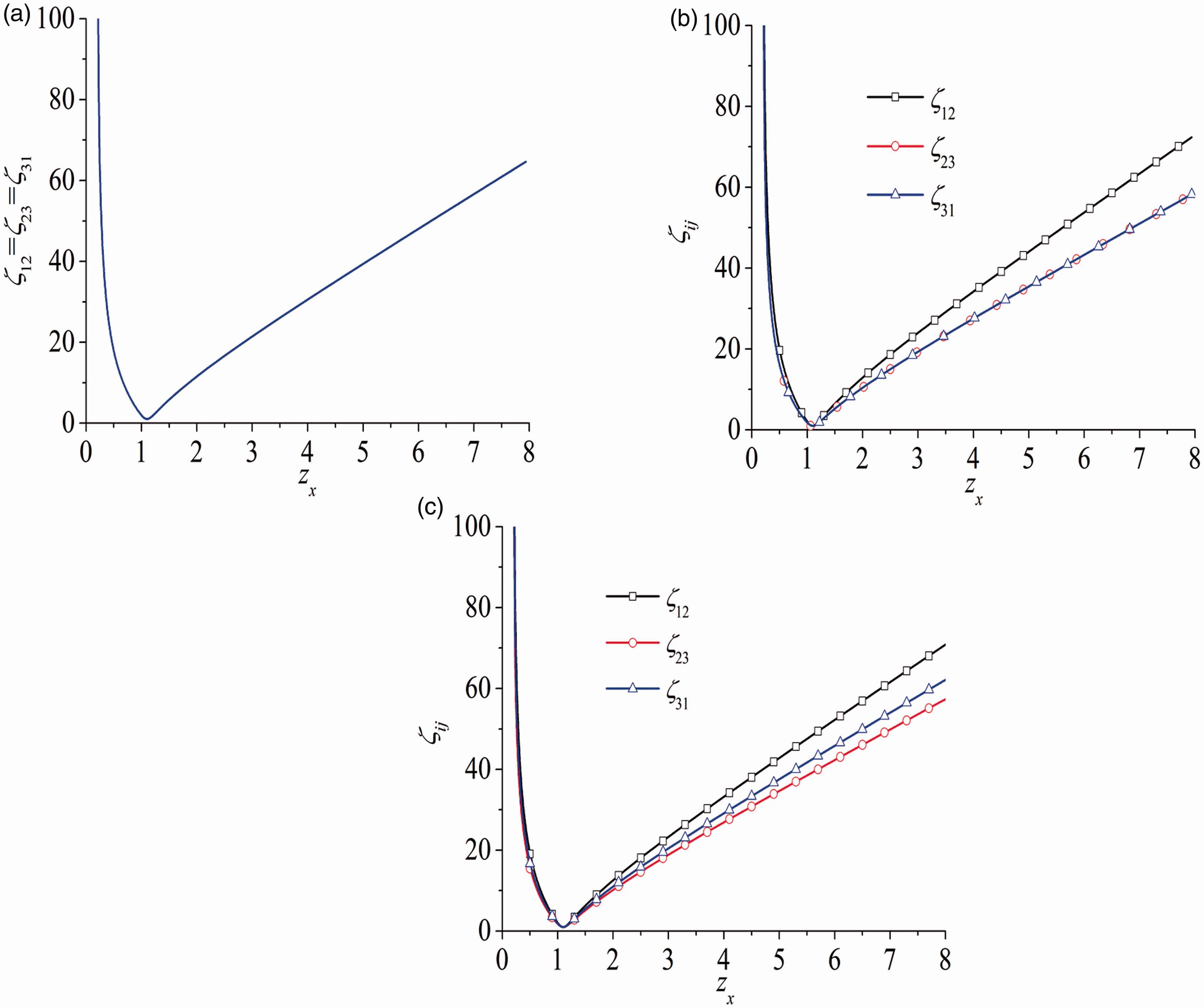
Figure 4 shows the values of CGDSs versus for different . In Figure 4(a), the parameters of three exciters are identical, ; in other words, three exciters are symmetrical and the coefficients of synchronization ability satisfy . In Figure 4(b), , exciters 1 and 2 are symmetrical, the coefficients of synchronization ability satisfy . In Figure 4(c), , and , the relationship among () is clear, i.e., . It can be found that when is close to 1, the value of CGDS approaches to zero. Hence, the resonance phenomenon occurs when the synchronous rotational velocity approaches or reaches the resonance point. The closer to 1 is, the easier to achieve resonance the system is, and the weaker the synchronization ability is.
CGDSs versus for different : (a) ; (b) , ; and (c) , , .
Discussions on stability of the synchronous states
According to equation (6), under the condition that the synchronization criterion is satisfied, the phase differences , and the operating frequency satisfy stability criterion, the stable difference values of phase can be obtained by changing the value of .
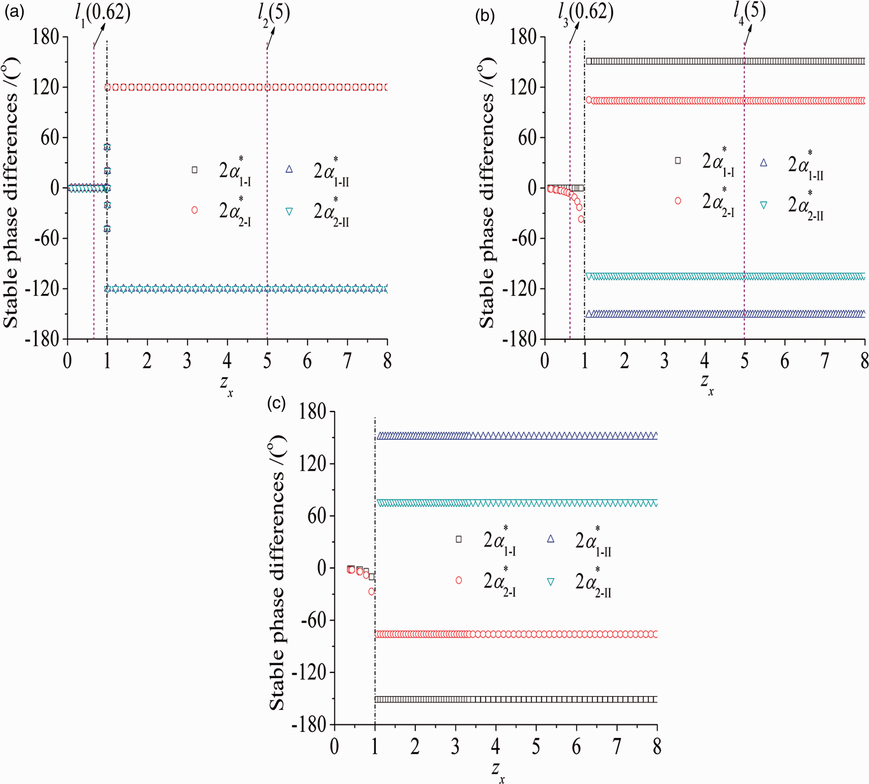
As illustrated in Figure 5, the stable difference values of phase can be divided into two regions: sub-resonant state () and super-resonant state (). In the case of , the stable state of single equilibrium point is occurred; in other words, the stable phase differences are under the condition of three identical motors (i.e., ). Similarly, exciters 1 and 2 are identical in Figure 5(b), the stable difference of phase satisfies . It demonstrates that the stable difference value of phase is equal to zero when two exciters are identical; therefore, three exciters operate with the same phase and the interval of stable phase differences is (), the exciting forces implement positive superposition, and the vibrating system has large amplitude.
Stable difference values of phase versus for different : (a) ; (b) , ; and (c) , , .
If , two equilibrium points can be reached, the phenomenon that the vibrating system has double equilibrium points is called as the diversity of nonlinear system. What is more, the stable difference values of phase approach to constant with the increasing , and the constant values of stable phase differences can be roughly found: (a) , it has ; (b) , , it has , ; (c) , , , it has , .
When is close to resonance point (i.e., ), there are several or no equilibrium points, which indicates that the system is unstable.
Based on the change of the stable difference values of phase with the increasing , the motion type of the rigid frame can be predicted. In the interval of , the motion type is linear motion; in the interval of , the exciting forces of three exciters are balanced with each other; therefore, the motion type of the rigid frame is nonvibration.
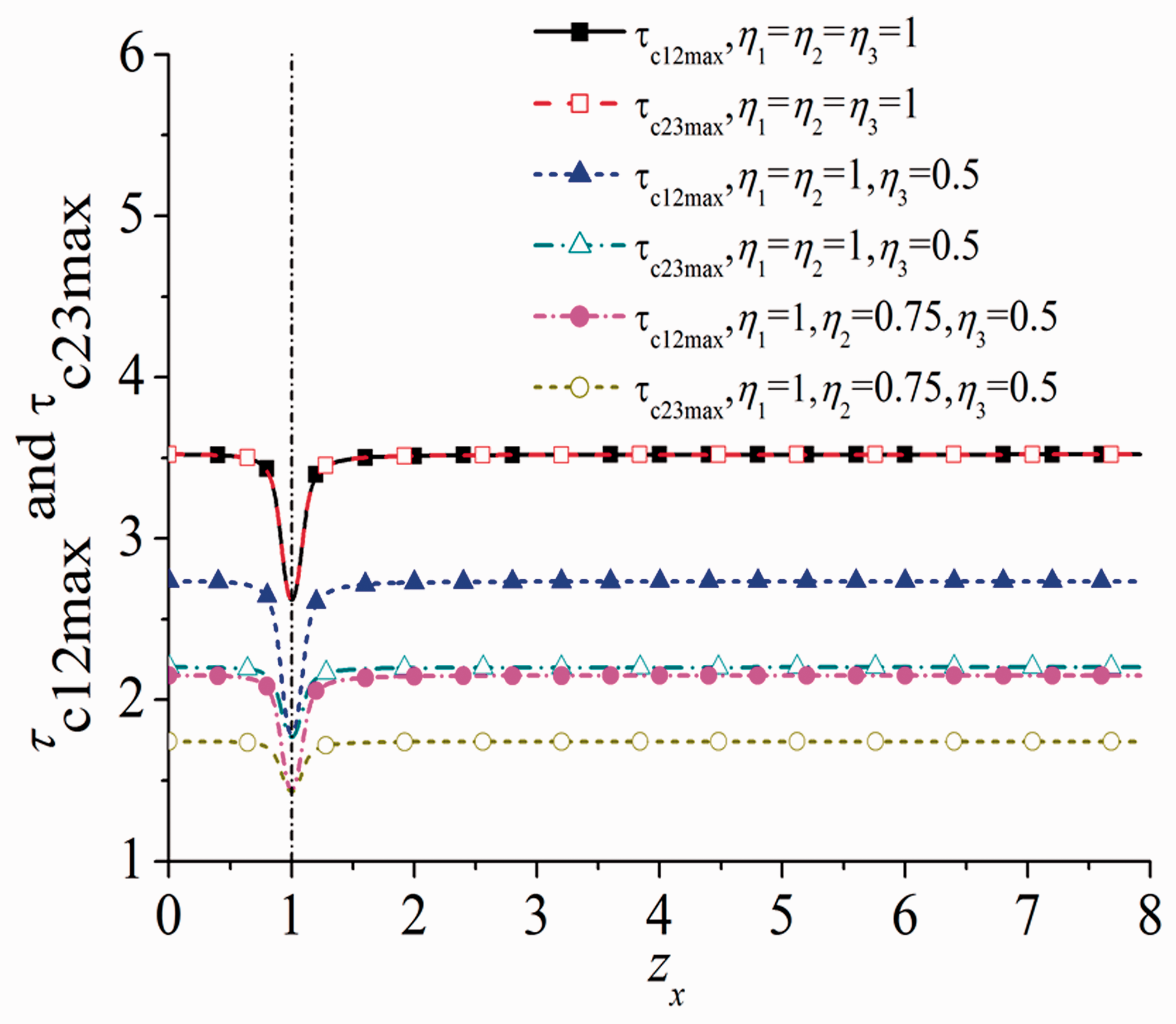
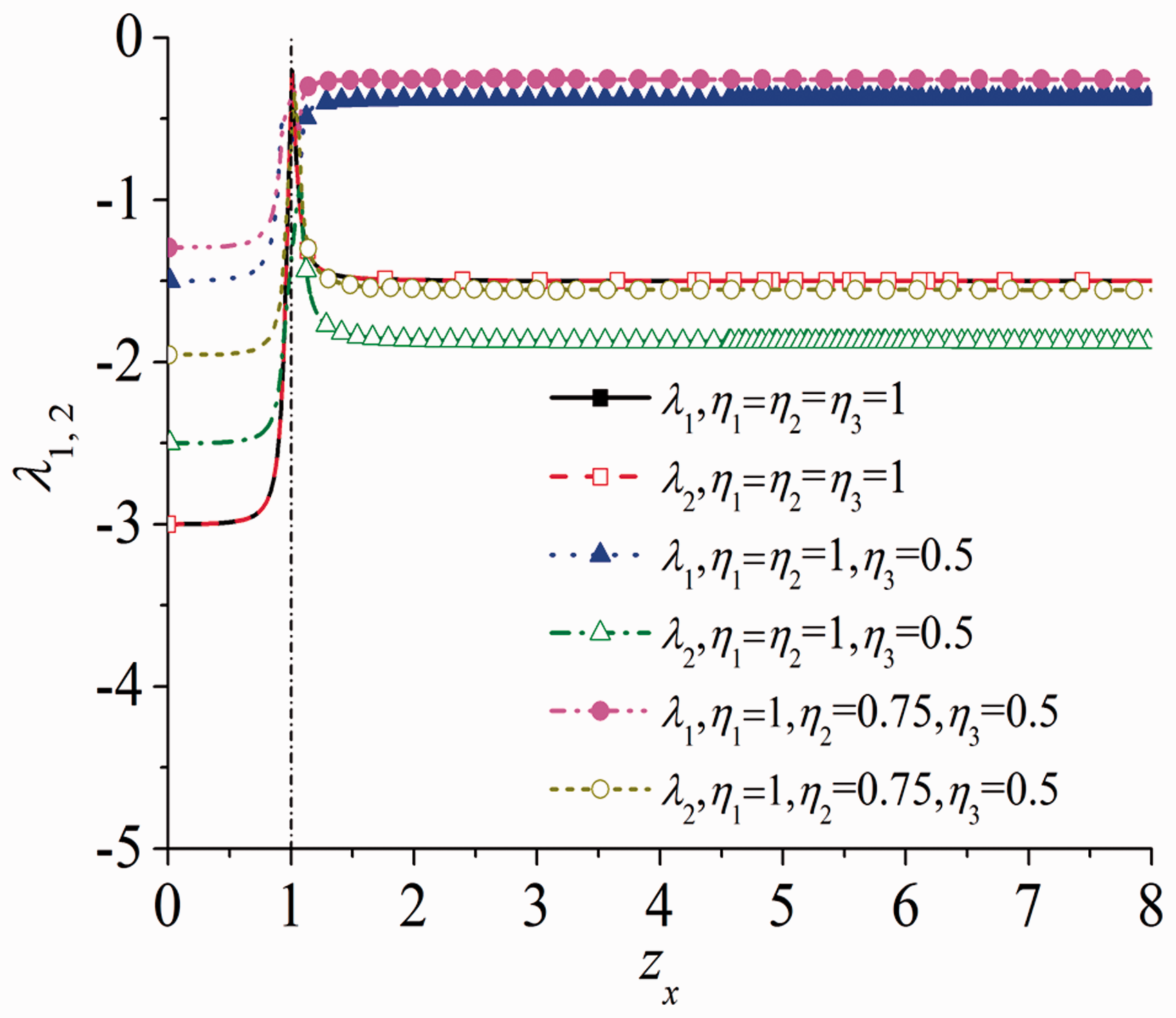
During the process of stability analyses, the stability criterion of the synchronous states is obtained by Routh–Hurwitz criterion. In order to further analyze and study the synchronization stability, the negative real parts about eigenvalues and of matrix D are referred to as the standards of synchronization stability ability. It can be considered that the closer to zero the coefficient of synchronization stability ability is, the weaker the synchronization stability ability of the system is. Figure 6 illustrates the curves of and ; comparing them for different , it is easy to draw the conclusion that and are smaller relative to other cases when , and the synchronization stability ability is stronger. It can be also noted that when is in the vicinity of 1, the values of and are the largest and close to zero. It manifests that the synchronization stability of the system is the weakest near the resonance point.
Stability ability coefficients versus for different .
Computer simulations
In order to further analyze the numerical results quantitatively, four groups of simulation results are performed by applying a Runge–Kutta routine to equation (1). The parameters of the system are listed in “Numeric analyses on the coupling dynamical characteristics” section, and we will discuss the simulation results in detail.
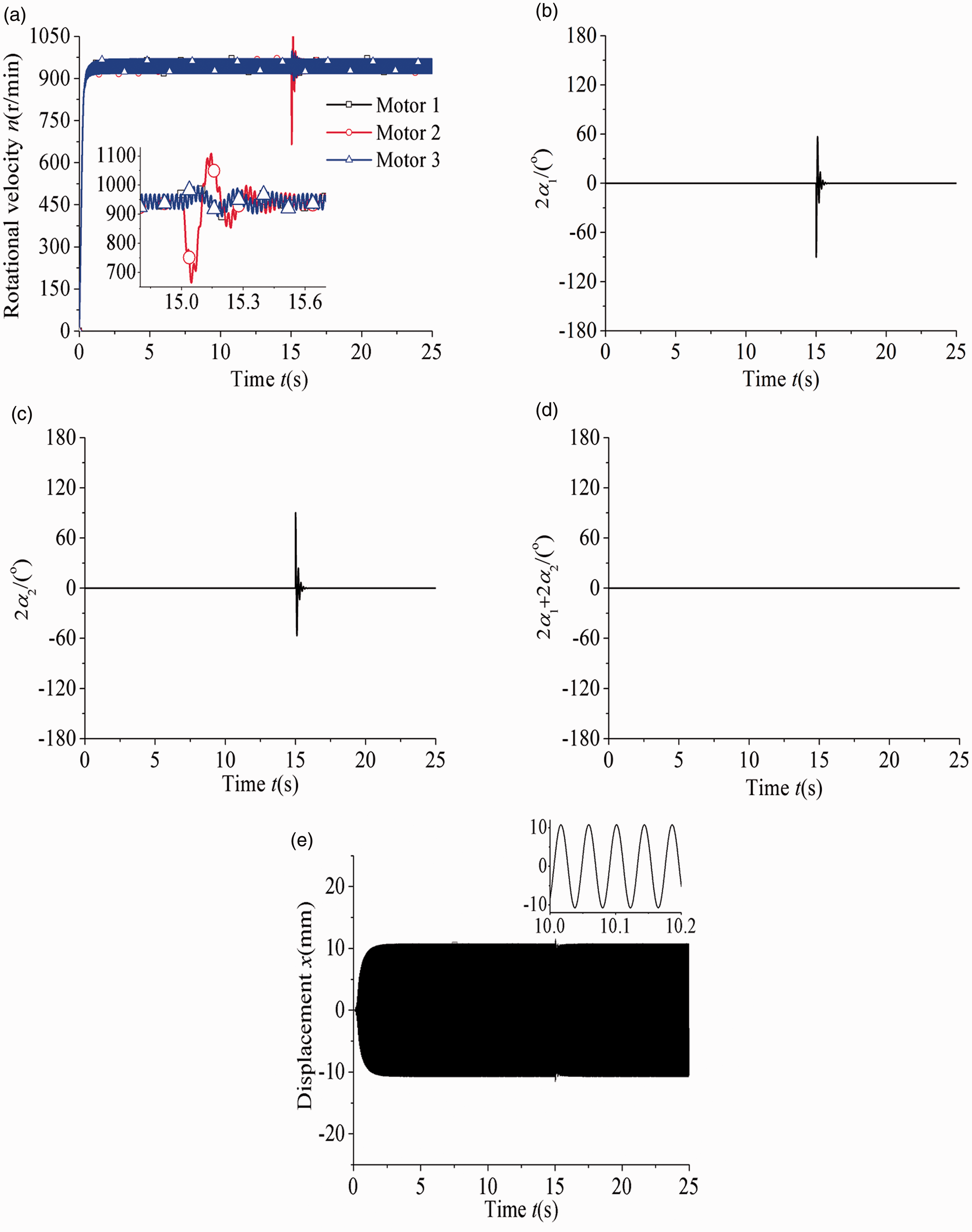
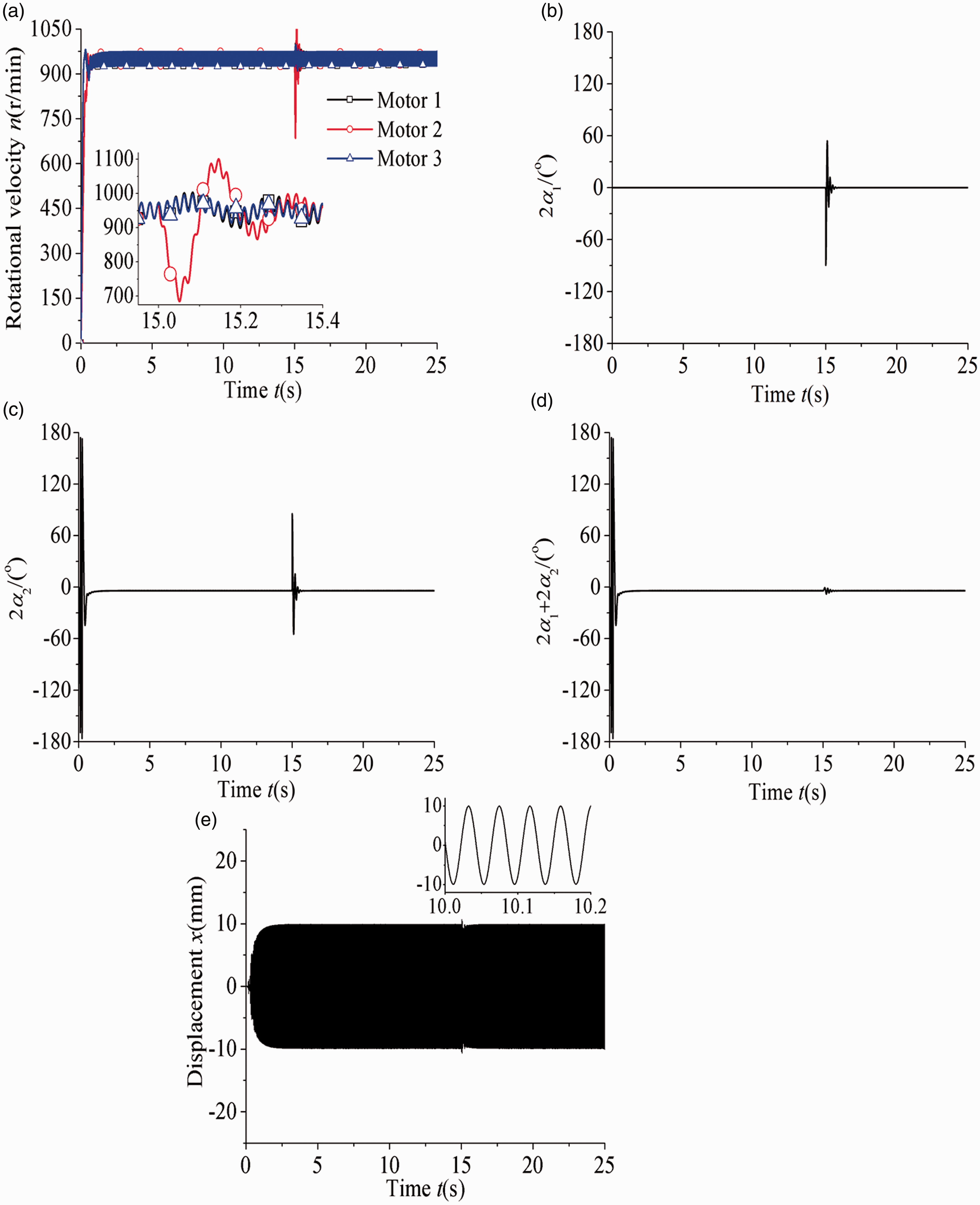
As shown in Figures 7 and 8, , , three exciters all operate in a sub-resonant state. The stable differences of phase: for ; , for , . The synchronous rotational velocities are both stabilized around 940 r/min. When three motors operate steadily, the average displacement of the rigid frame is around 10.8 mm for and 9.8 mm for , . Comparing simulation results in Figures 7 and 8 with numerical ones of stable phase differences in Figure 5, it can be found that the results of simulations are consistent with the lines (, ) and (, ) in Figure 5(a) and (b). When time reaches about 15 s, a disturbance of π/2 is added to motor 2, and the phase difference between exciters 1 and 3 is invariant (the fluctuation for , is so small to ignore). Simultaneously, the phase differences between exciters 1 and 2 and that between exciters 2 and 3 are increasing rapidly at a short period, and they are exactly opposite. In addition, there exists a little displacement fluctuation at 15 s in Figures 7(e) and 8(e).
Simulation results in a sub-resonant state () for : (a) rotational velocities of three motors, (b) difference of phase between exciters 1 and 2, (c) difference of phase between exciters 2 and 3, (d) difference of phase between exciters 1 and 3, and (e) displacement in x-direction.
Simulation results in a sub-resonant state () for , : (a) rotational velocities of three motors, (b) difference of phase between exciters 1 and 2, (c) difference of phase between exciters 2 and 3, (d) difference of phase between exciters 1 and 3, and (e) displacement in x-direction.
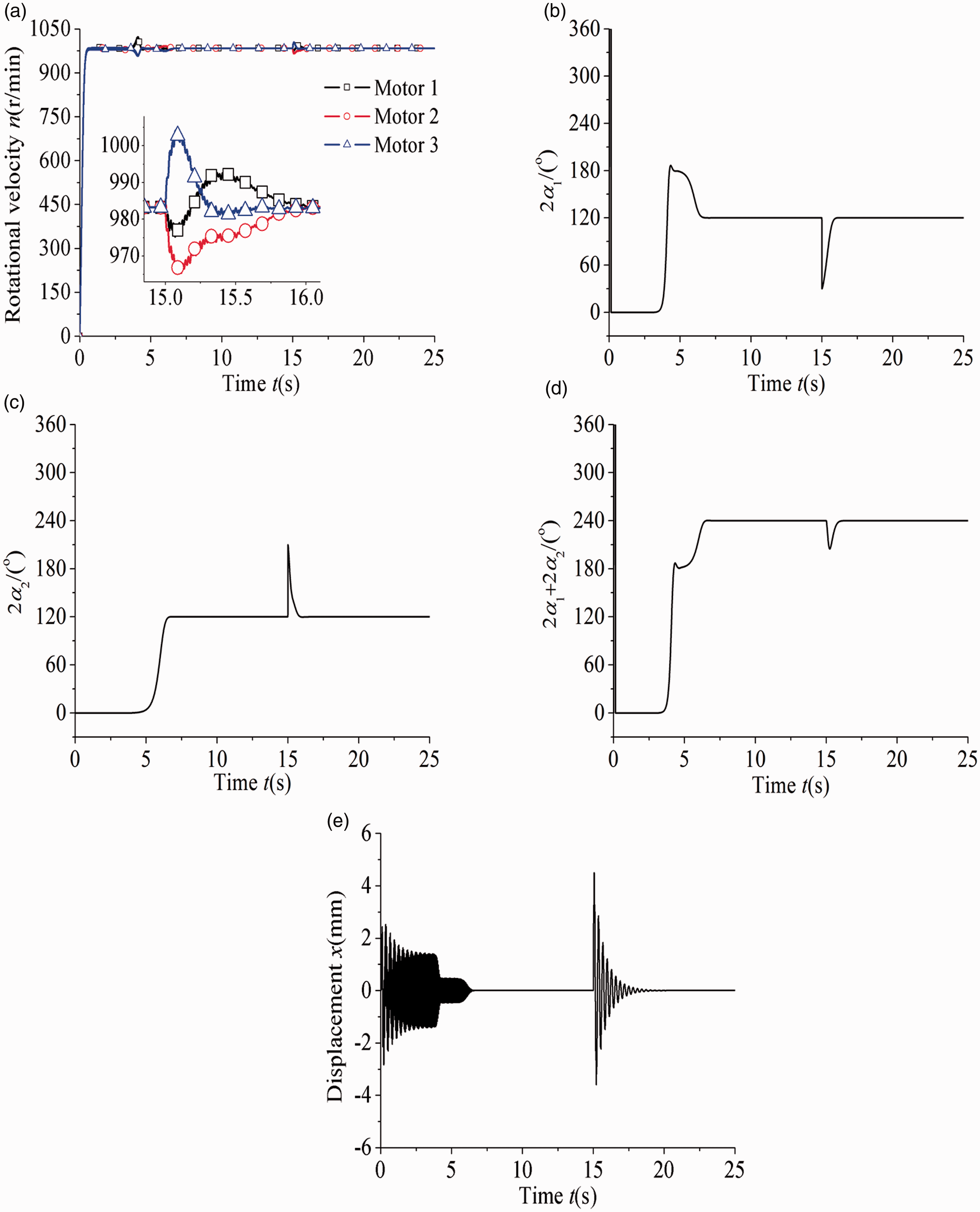
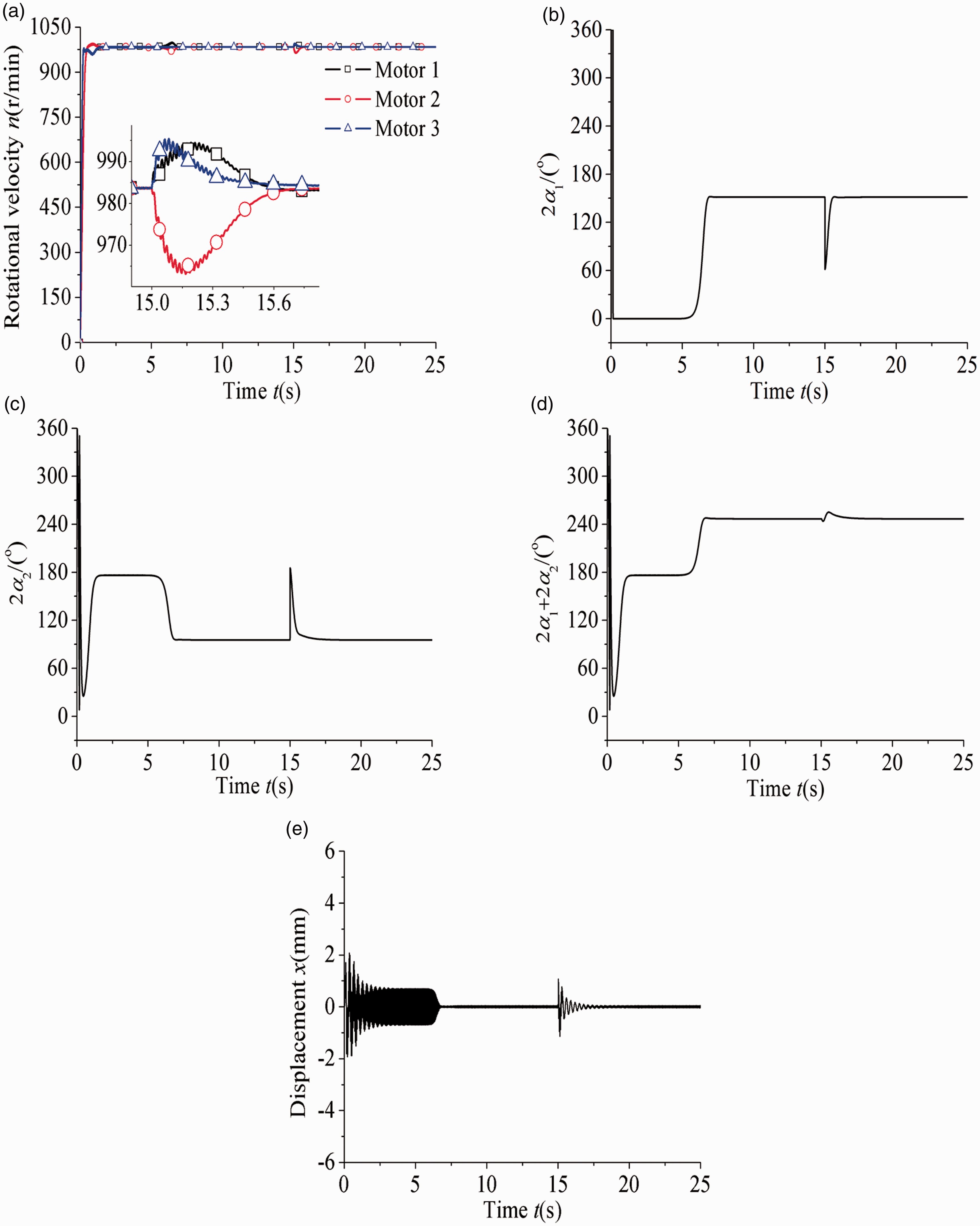
Figures 9 and 10 show the simulation results for and those for , , respectively. It is known that , and the stable difference values of phase: for ; , for , . Three exciters all operate in a super-resonant state and the synchronous rotational velocities are both near 983 r/min. Under the condition of , the average amplitude of the rigid frame is zero when three motors are operating steadily. Comparing simulation results in Figure 9(b) and (c) with numerical ones in Figure 5(a), it can be found that the above facts coincide with what is shown in Figure 5. When time is 15 s, a disturbance of π/2 is added to the motor 2, the phase differences among three exciters are fluctuated at a short period, and will return to with time. As illustrated in Figure 9(e), the displacement is increasing in a short time at 15 s, then it tends to zero with time going on. It can be also noticed that the state of motion is instability before about 7 s and this period can be called the transitional region.
Simulation results in a super-resonant state () for : (a) rotational velocities of three motors, (b) difference of phase between exciters 1 and 2, (c) difference of phase between exciters 2 and 3, (d) difference of phase between exciters 1 and 3, and (e) displacement in x-direction.
Simulation results in a super-resonant state () for , : (a) rotational velocities of three motors, (b) difference of phase between exciters 1 and 2, (c) difference of phase between exciters 2 and 3, (d) difference of phase between exciters 1 and 3, and (e) displacement in x-direction.
Under the circumstance of and , comparing simulation results in Figure 10(b) and (c) with numerical ones in Figure 5(b), the simulation result of is smaller, but the changing value of which is much less than the numerical result of . Moreover, the amplitude of the rigid frame in the steady state is very small but not zero. In response to this phenomenon, the vibrating system has small amplitude due to the effect of damping. To balance the system load, the induction motor will generate enough coupling torques by changing the stable phase differences.
Conclusions
On the basis of the theoretical and numerical analyses, the following conclusions are drawn:
Under the circumstance that the small damping of the vibrating system is not neglected, the motion state of the rigid frame is discussed and classified into two types: (i) sub-resonant state and (ii) super-resonant state. The motion type of the rigid frame is strong superposition vibration in a sub-resonant state; while in a super-resonant state, due to the mutual cancellation of the exciting forces of three exciters, the rigid frame has no vibration.
Specifically, when three exciters are completely identical, the phase differences of three exciters are stabilized in the neighborhood of zero for a sub-resonant state; otherwise, in the vicinity of 2π/3 coincide with a super-resonant state. In view of the former, the energy can be saved, which is exactly desired in engineering. In contrast with that in sub-resonant and super-resonant states, the motion state is instability when it nears the resonance point, because there exist multiple equilibrium points or no equilibrium point.
In the existing investigation results, which focus on synchronization of three exciters in a super-resonant vibrating system, in this case the power of system cannot be improved by using three exciters instead of two. In this paper, however, the power of system with three exciters is obviously improved by setting one ideal working point region (i.e., sub-resonant state). The present work can lay a foundation for designing a new type of the long-distance vibrating conveyor, which can not only implement energy saving, but also the work performance of the vibrating machines is relatively best in a sub-resonant state when three identical exciters are selected.
Footnotes
Declaration of conflicting interests
The author(s) declared no potential conflicts of interest with respect to the research, authorship, and/or publication of this article.
Funding
The author(s) disclosed receipt of the following financial support for the research, authorship, and/ or publication of this article: This work was funded by the National Natural Science Foundations of China (51675090), the Fundamental Research Funds for the Central Universities (N170304013), and China Postdoctoral Science Foundation (2017M621145).
Appendix
References
1.
OrangeSVerdièreN.Nonlinear synchronization on connected undirected networks. Nonlinear Dyn2014;
76: 47–55.
2.
HanFLuQSWiercigrochMet al.
Chaotic burst synchronization in heterogeneous small-world neuronal network with noise. Int J Non-Linear Mech2009;
44: 298–303.
3.
PerlikowskiPStefańskiAKapitaniakT.1:1 mode locking and generalized synchronization in mechanical oscillators. J Sound Vib2008;
318: 329–340.
4.
FangPHouYJNanYHet al.
Study of synchronization for a rotor-pendulum system with Poincare method. J Vibroeng2015;
16: 2681–2695.
5.
FukuharaHOhkumaT.Low frequency measurement by synchronized integrating method and influence of reflecting object. J Low Freq Noise Vib Active Control1983;
2: 85–95.
6.
YamapiRWoafoP.Dynamics and synchronization of coupled self-sustained electromechanical devices. J Sound Vib2005;
285: 1151–1170.
7.
HuygensC.Horologium oscillatorium.
Paris: Apud F. Muguet, 1673.
8.
RayleighJ.Theory of sound.
New York:
Dover, 1945.
9.
Van der PolB.Theory of the amplitude of free and forced triode vibration. Radio Rev1920;
1: 701.
10.
BlekhmanII.Vibrational mechanics.
Singapore:
World Scientific, 2000.
11.
BlekhmanIIFradkovALNijmeijierHet al.
On self-synchronization and controlled synchronization. Syst Control Lett1997;
31: 299–305.
12.
BlekhmanIIFradkovALTomchinaOPet al.
Self-synchronization and controlled synchronization: general definition and example design. Math Comput Simul2002;
58: 367–384.
13.
BlekhmanIISorokinVS.On the separation of fast and slow motions in mechanical systems with high-frequency modulation of the dissipation coefficient. J Sound Vib2010;
329: 4936–4949.
14.
WenBCFanJZhaoCYet al.Vibratory synchronization and controlled synchronization in engineering.
Beijing:
Science Press, 2009.
15.
WenBCZhangHLiuSYet al.Theory and techniques of vibrating machinery and their applications.
Beijing:
Science Press, 2010.
16.
BalthazarJMFelixJLPBrasilRM.Short comments on self-synchronization of two non-ideal sources supported by a flexible portal frame structure. J Vib Control2004;
10: 1739–1748.
17.
BalthazarJMFelixJLPBrasilRM.Some comments on the numerical simulation of self-synchronization of four non-ideal exciters. Appl Math Comput2005;
164: 615–625.
18.
NijmeijerH.A dynamical control view on synchronization. Phys D2001;
154: 219–228.
19.
FradkovAAndrievskyB. Singular perturbations of systems controlled by energy-speed-gradient method. In: The 43rd IEEE conference on decision and control, Atlantis, Paradise Island, Bahamas, 14–17 December 2004, pp.3441–3446.
20.
BianYSGaoZH.Nonlinear vibration control for flexible manipulator using 1: 1 internal resonance absorber. J Low Freq Noise Vib Active Control2018; 37: 1053–1066.
21.
ZhangXLZhaoCYWenBC.Theoretical and experimental study on synchronization of the two homodromy exciters in a non-resonant vibrating system. Shock Vib2013;
20: 327–340.
22.
ZhangXLWenBCZhaoCY.Vibratory synchronization transmission of two exciters in a super-resonant vibrating system. J Mech Sci Technol2014;
28: 2049–2058.
23.
ZhangXLWenBCZhaoCY.Vibratory synchronization transmission of a cylindrical roller in a vibrating mechanical system excited by two exciters. Mech Syst Signal Process2017;
96: 88–103.
24.
ZhaoCYZhuHTWangRZet al.
Synchronization of two non-identical coupled exciters in a non-resonant vibrating system of linear motion part I: theoretical analysis. Shock Vib2009;
16: 505–516.
25.
LuQS.Qualitative methods and bifurcations of ordinary differential equations.
Beijing:
Press of Beijing, University of Aeronautics and Astronautics, 1989 (in Chinese).