A new dynamical model with five rigid frames (RFs), driven by two counter-rotating exciters, is proposed to explore the synchronization, stability, and motion characteristics of the system in this paper. The motion differential equations and the corresponding responses of the system are given firstly. Using the average method, the average torque balance equations for the two exciters are deduced. According to the relationship between the difference of the dimensionless effective output electromagnetic torques for the two motors and the coupling torques of the system, the theory condition of realizing synchronization is obtained. Based on the Hamilton’s theory, the theory condition of stability of the system is deduced. The stability and motion characteristics of the system for different resonant regions are qualitatively discussed in numeric, including the stable phase difference of the two exciters, relative phase relationships among the five rigid frames, amplitude-frequency characteristics, stability coefficients, and the effective load torque between the two exciters. Simulations are carried out to further quantitatively validate the feasibility of the above theoretical and numerical qualitative results. It is shown that in engineering the reasonable working points of the system should be selected in Region II, only in this way, can the synchronous and stable relative linear motion of the system with the zero stable phase difference in vertical direction be realized, and in this case, the vibrations of the four inner rigid frames (IRFs) in the horizontal direction are compensated with each other, and the energy is also saved due to utilizing the resonant effect. Based on the present work, some new types of vibrating coolers/dryers or vibrating screening machines can be designed.
The problems and researches about vibrations in engineering and technology fields generally consist of vibration suppression and vibration utilization. For the former, which are related to the vibration isolations, such as vibration absorbers;1–3 while for the latter, one of the most important representatives is the synchronization of exciters (generally unbalanced rotors driven by induction motors separately), based on which many new vibrating machines can be invented and widely used in the industrial production process, implement the screening, cooling/drying, conveying, feeding of the materials, and so on, and more and more researchers are inspired to investigate it.
As for the synchronization phenomenon, we have to date back to the synchronization of clock pendulums found by Huygens.3 In early times, the synchronization of a certain electrical- mechanical system was proposed by Van der Pol.4 In connection with the development of synchronization of exciters, we should also mention the findings by Blekhman,5–7 who firstly gave a theoretical explanation of two identical exciters by using Poincare–Lyapunov small parameters method, and from then on, he deeply developed synchronization theory and facilitated its practical application.
Until synchronization theory of exciters was found to be of great engineering applicable prospects, more and more scholars and engineers have been paying more attentions to studying it. Inoue et al.8 explored the multiple cycle synchronization of the mechanical system, including the synchronization problem with two (or three) times frequency. Considering the damping effects of the system, Wen et al.9,10 studied the synchronization with n (n1) times frequency, by which many new vibrating machines were invented and applied to engineering successfully. Balthazar et al.11,12 analyzed the synchronization problem of non-ideal exciters on the flexible portal frame structure by numeric method. Fang et al.13,14 studied the synchronization characteristics of the rotor-pendulum system. Chen et al.15 revealed the synchronization of the two exciters with a common rotational axis in a far-resonant vibrating system and discussed the stability of the system with different key parameters. Zhang et al.16,17 studied the synchronization problem and dry friction effect of a far-resonant vibrating system with three rollers driven by two exciters, and the stability and Sommerfeld effect of a vibrating system with two exciters driven separately by induction motors. Kong et al.18–20 gave the controlled synchronization and composite synchronization of three or four eccentric rotors and analyzed the Sommerfeld effect and self-synchronization of two non-ideal induction motors in a simply supported beam.
In the abovementioned studies on synchronization of exciters, most of them are focused on that in a vibrating system with single or double rigid frames (RFs), while the synchronization and stability of exciters in a multiple RFs (more than two RFs, such as five RFs) vibrating system are less considered, the former (single or double RFs) has lower working efficiency than the latter (multiple RFs). In this paper, a new dynamical model with five RFs in which four inner rigid frames (IRFs) are working RFs is proposed to further enhance the processing capacity of the machine. To make the system structure more compact and reduce the floor space, the modular design of subsystems and the structure of the combination of series and parallel among IRFs are adopted. At the same time, from the point of views of engineering applications, the structure of the system makes the maintenance of the core unit more convenient. In addition, in order to improve the isolative effect of the system and make full use of the space, the inclined angles between the springs connected to IRFs and the horizontal line are actively set up. Based on this new dynamical model, some new types of vibrating machines, such as vibrating cooling/drying fluidized bed, and vibrating screens, can be designed. And the compact modular design and the structure of the series-parallel connection of the system not only increase the drying/cooling or screening time of materials but also improve the processing capacity and working efficiency of the system, which has a strong application background in engineering.
In the previous studies on synchronization of exciters, the ideal working point of self-synchronous vibrating machines is often considered to be in a far super-resonant state, while the synchronization and stability characteristics in the sub-resonant state are less considered. The motion characteristics of the dynamical model with five RFs proposed in this paper are discussed in different resonance regions, and then we can select the ideal working region of the system which not only has strong stability but can also save energy, which is just the desire in engineering.
In this paper, a new dynamical model with five RFs and two exciters and the motion differential equations are given firstly, and the synchronization and stability of the system will be investigated in detail by theory. Next, some numerical qualitative analyses and simulations are provided, and simulations are carried out to further quantitatively examine the validity of the theoretical and numerical qualitative results. Finally, conclusions are provided.
Dynamical model and motion differential equations of the system
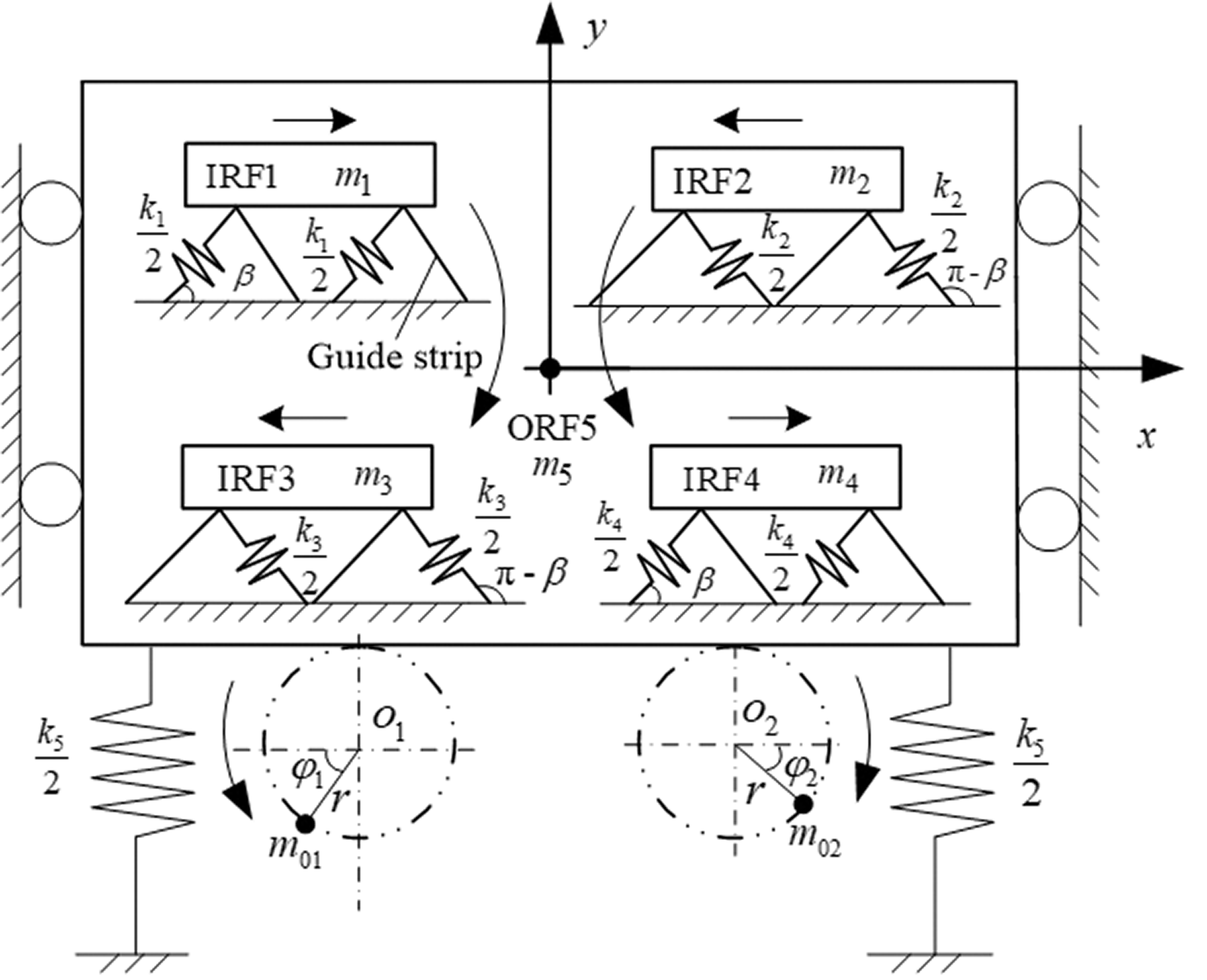
As shown in Figure 1, a new dynamical model consists of five RFs and two driving exciters, of which the former is composed of four IRFs and one outer rigid frame (ORF), meanwhile, each exciter is made up of an unbalanced rotor driven by one induction motor. The ORF (mass ) is connected to the foundation by springs with stiffness k5. Each IRFi (i =1,2,3,4) corresponding to mass is linked to the ORF by guide strips and springs with stiffness , respectively. And the included angles between the directions of action of the springs and the horizontal line can be fixed by or with the help of the guide strips, where the guide strips can contribute the function that the springs can stretch along with their action directions.
Dynamic model of a considered vibrating system with five RFs and two exciters. ORF: outer rigid frame; IRF: inner rigid frame.
It should be stressed that the inclined angles ( or ) between the springs and the horizontal line have mainly three key contributions: (i) ensuring each IRF to achieve motion by a certain direction with or , which facilitates each IRF to transport materials along the way indicated by the arrow in Figure 1; (ii) the vibrating forces of the two IRFs located on the same horizontal line can be compensated with each other in the horizontal direction, this leads to the realization of self-balancing of four IRFs in the horizontal direction, so that the dynamic loads transmitted to the foundation in horizontal direction is 0, and based on which and the ideal isolation effect is obtained as possible, this is just the desire in engineering; (iii) the four IRFs are grouped together by the way of combination of series and parallel, where and are grouped together in series (called group 1) as well as and (called group 2), while the group 1 and group 2 are arranged together in parallel; in this case, the two series production lines can work in parallel so that materials can be moved along two lines as shown by the arrows, in this way, the movement time of the materials in the working face is prolonged, the occupation space of machines is effectively utilized, and finally the technological effect (such as drying and cooling effect) of the machine is improved.
Additionally, the two exciters rotating in reverse about their own spin axis are installed symmetrically below the ORF, their rotating phases are denoted by φ1 and φ2, and the other parameters are seen in Figure 1. It should be noted here that the main motion of the system are displacements in x- and y-directions, and there is no vibration for ORF in x-direction, while the four IRFs reflect a certain vibration in x-direction with the help of guide strips.
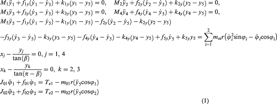
Substituting the kinetic energy, the potential energy, and the energy dissipation functions of the system into Lagrange’s equations, the motion differential equations of the system are presented directly as follows
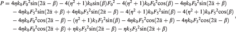
where (i =1, 2, 3, 4), ; (i =1, 2) and are the mass of exciter i and its eccentric radius; is the moment of inertia of the exciter i (i =1, 2), ; is the stiffness coefficient of the system in y-direction; is the damping coefficient of the system in y direction; is the damping coefficient of the axis of the motors i; denotes the electromagnetic output torque of the motor i, which detailed expressions and the corresponding relationship with the electrical parameters can be seen in Zhao et al.21
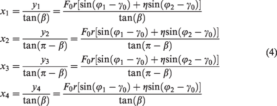
Besides, for the motion equation in x-direction of equation (1), due to the existence of the guide plates between four IRFs and ORF, which can ensure that the IRFs can move by an inclined angle of relative to the horizontal direction, see Figure 1, so the motion responses of IRFs in x-direction can be obtained directly by their responses in y-direction.
Theory conditions on synchronization and stability of the system
Responses of the system in x- and y-directions
Due to the fact that the present dynamic model belongs to a multi-body system, it is necessary to study its responses in the steady state.
It is assumed that the average phase of the two exciters is and their phase difference is , we have
where and are the phases of the two exciters, respectively.
We assume that two exciters are identical, the masses of four IRFs are the same, as well as the corresponding stiffness and damping constants of the system, that is ,
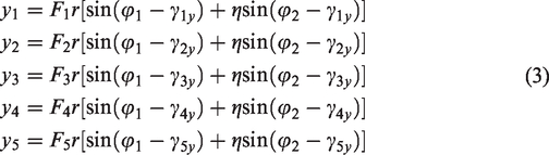
If the two exciters can implement synchronous operation in the steady state, we set as ; in this case, the angular acceleration of each exciter is zero, that is, . We also set , and based on the transfer function method22 in the steady state, the responses of the system for y-direction can be obtained as follows
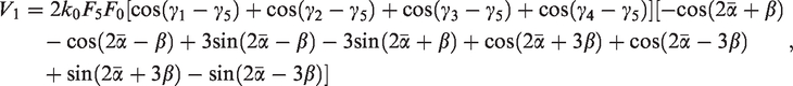
where , , , , and the other details are seen in the Appendix.
Considering equations (1) and (3), the responses of the four IRFs in x-direction are given directly as
Theoretical condition of implementing synchronization of the system
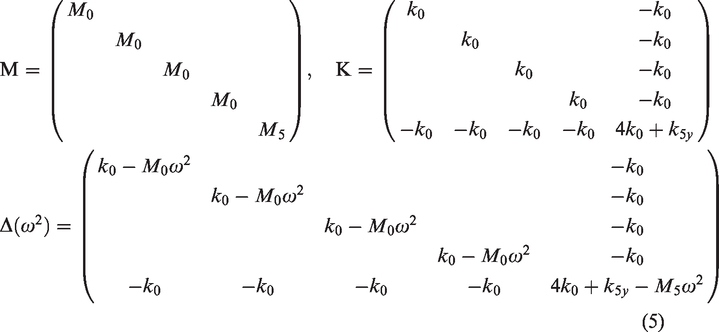
According to the first five formulae of equation (1), the mass matrix M, the stiffness matrix K, and the characteristic equation of the system can be obtained as
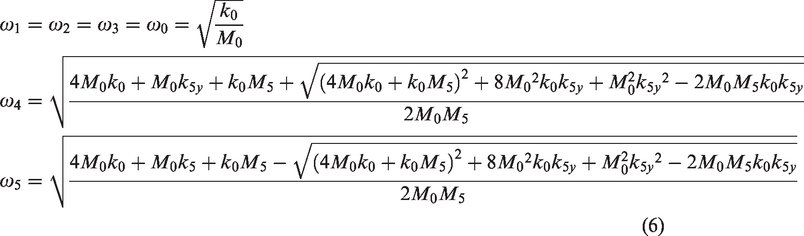
Here, the condition of is satisfied, the natural frequencies of the system denoted by (i = 1,2,3,4,5) are given as
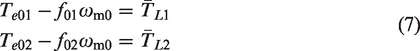
Differentiating the last formula of equation (3), and inserting the results into the last two formulae of equation (1), then integrating them over and taking the mean, finally the average torque balance equations of two exciters are expressed as
where
In equations (8) and (9), denotes the kinetic energy of the standard exciter; (i =1, 2) represents the load torque of the motor i; denotes the electromagnetic output torque of the motor i when the system operates at the average angular velocity . Besides, during the process of integral above, compared with changes of by time t, changes very small, so the phase difference might be considered as the slow-changing parameter,5–7 which has been replaced by its integral mean value .
The subtraction of the two formulae in equation (7) and after the rearrangement yields to
where
with is the difference of the effective output electromagnetic torque between the two motors.
with is the difference of the dimensionless effective load torque between two exciters. Due to the fact that is a constraint function of , only the following condition
is satisfied, can equation (10) be solved with respect to and , which are called the synchronous solutions of the system, denoted by and , respectively. Hence, the synchronization condition of implementing the synchronous operation of the system is equation (13), which can construct a kind of the energy relationship between the inner output torques of the two motors and the outer coupling torques of the two exciters.
Besides, from equation (13), generally speaking, under the precondition of satisfying synchronization condition (i.e., equation (13)), has two synchronous solutions, of which one is stable, while the other is unstable, and each synchronous solution corresponds to a kind of motion state of the system. Which one is the final stable state of the system? It depends on the stability condition in the following section.
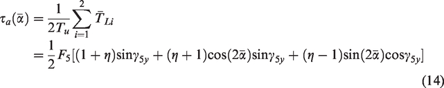
Summing the two formulae of equation (7), and after the dimensionless treatment, we can obtain the average dimensionless load torque of the two motors, denoted by , that is
Here, is also a constraint function of , that is
We here define the synchronization ability coefficient of the two exciters, denoted by , that is
The greater the value of , the stronger the synchronization performance of the system, that is, it is easier for the two exciters to implement synchronization.
Theoretical condition on stability of the synchronous states
Since not all the synchronous solutions are stable in equation (10), so it is very necessary to investigate the stability of the system.
The kinetic energy (Ep) and the potential energy (Ek) of the system are obtained by
Thus, the average kinetic energy () and average potential energy () equations over one period are yielded as
where
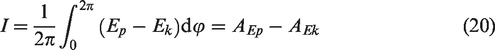
According to equations (17) to (19), the Hamilton’s average action amplitude of the system over one period, denoted by I, is deduced by
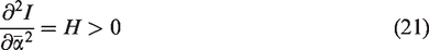
Based on Wen et al.,9,10 the stable phase difference between two exciters should be in accordance with the minimum of the Hamilton average action amplitude of the system, that is, the following expression
should be satisfied. So, equation (21) is the stability criterion of the synchronous states of the system.
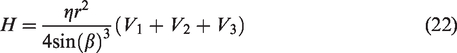
In equation (21), the detailed expression of H is given in form
where
Here, H is defined as the coefficient of ability of synchronous stability, which will be discussed by numeric in the following section, and the greater the value of H, the stronger stability of the synchronization states of the system.
Numerical qualitative analyses on characteristics of the system
According to the above theory results, in this section, some numerical qualitative discussions are given to further reveal the motion characteristics of the system. The two driving motors are selected to be the same: model is three-phase squirrel-cage (50 Hz, 380 V, 6-pole, 0.75 kW, rated speed 980 r/min); the rotor resistance , the stator resistance , the mutual inductance , the rotor inductance , the stator inductance , and damping coefficients of axes of the motors are . The other parameters of the system: , , , , , , and . Based on the above given parameters, the main natural frequencies of the system are calculated as and , the value of is too small to be considered in engineering practice, and the system is here divided into three resonant regions according to the different values of the ratio between the operating frequency and natural frequencies as follows:
Region I: (), that is, sub-resonant region relative to ω0;
Region II: (), that is, super-resonant region with respect to ω0 and sub-resonant region relative to ω4;
Region III: (), that is, super-resonant region with respect to ω4.
In what follows, the double dot dash lines denote the boundary of regions, the corresponding simulation results with points A, B, and C will be given in Simulations section.
Characteristics on stability of the system
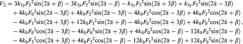
Substituting the parameters of the system into equation (13), and considering equation (21), the stable phase difference (SPD) between two exciters in the different resonant regions is plotted in Figure 2(a). From Figure 2, one can see that the SPD is zero in Region II and the first narrow range of Region III, and the corresponding motion types of the system: (i) in x-direction, four IRFs are the linear vibration and the ORF is no vibration; (ii) in y-direction, four IRFs and the ORF are all the linear vibration, see Figure 5(e). While in Region I and the last wide range of Region III, the SPD is ±180o, in this case, the system is at rest (i.e., four IRFs and the ORF are all no vibrations in x- and y-directions), see Figure 4(a) and (b), this is because that the exciting forces of two exciters are compensated with each other. These facts can also be verified by the following simulations in Simulations section.
Characteristics on stability of the system: (a) stable phase difference between two exciters, (b) stable phase relationship of the system in y-direction, (c) stable amplitude–frequency relationship of the system, and (d) coefficients of ability of stability of the system with the different values of κ.
Figure 2(b) shows the phase relationship between exciters and response of the system (the lag angles γiy), and the expression of γiy is given in equation (3). From Figure 2(b), we can see that in Region I the lag angles of the system are all equal to 180°. In Region II, γ5y corresponding to the ORF is near to 0°, while the other four lag angles related to the four IRFs all near to 180°, which indicates that the relationships between the isolation ORF and four inner main working IRFi are all opposite phase, this can also be examined by the following simulations of Figure 5. In Region III, γ5y changes to 180°, and the other lag angles change to nearing to 0° (or 360°).
From the expressions of equation (3), the amplitude–frequency relationships of the system can be obtained, as illustrated in Figure 2(c). Here, (i =1, 2, 3, 4, 5) denotes the amplitude of RFi in y-direction. In Region I, the response amplitudes of the system are all zero or near zero, this is because that the phase difference between two exciters is 180°, which causes the compensation of their exciting forces. While in Region II, the curves start increasing to a certain peak point for the natural frequency with the increase of , then drop down to nearing zero, in this case, the system has passed into Region III.
Figure 2(d) shows the coefficients of the stability ability of the system with the different values of κ (κ=m5/M0). Here, one can directly see that the values of H are all greater than zero, this means that the system can always ensure a certain stable state in three resonant regions with the different values of κ. The resonant point of ω4 corresponds to the maximum of stability ability in Figure 2(d), and the greater the value of the ratio between the mass of a single IRF and that of ORF, the higher the maximum of stability ability in Figure 2(d).
The difference of dimensionless effective load torque between the two exciters
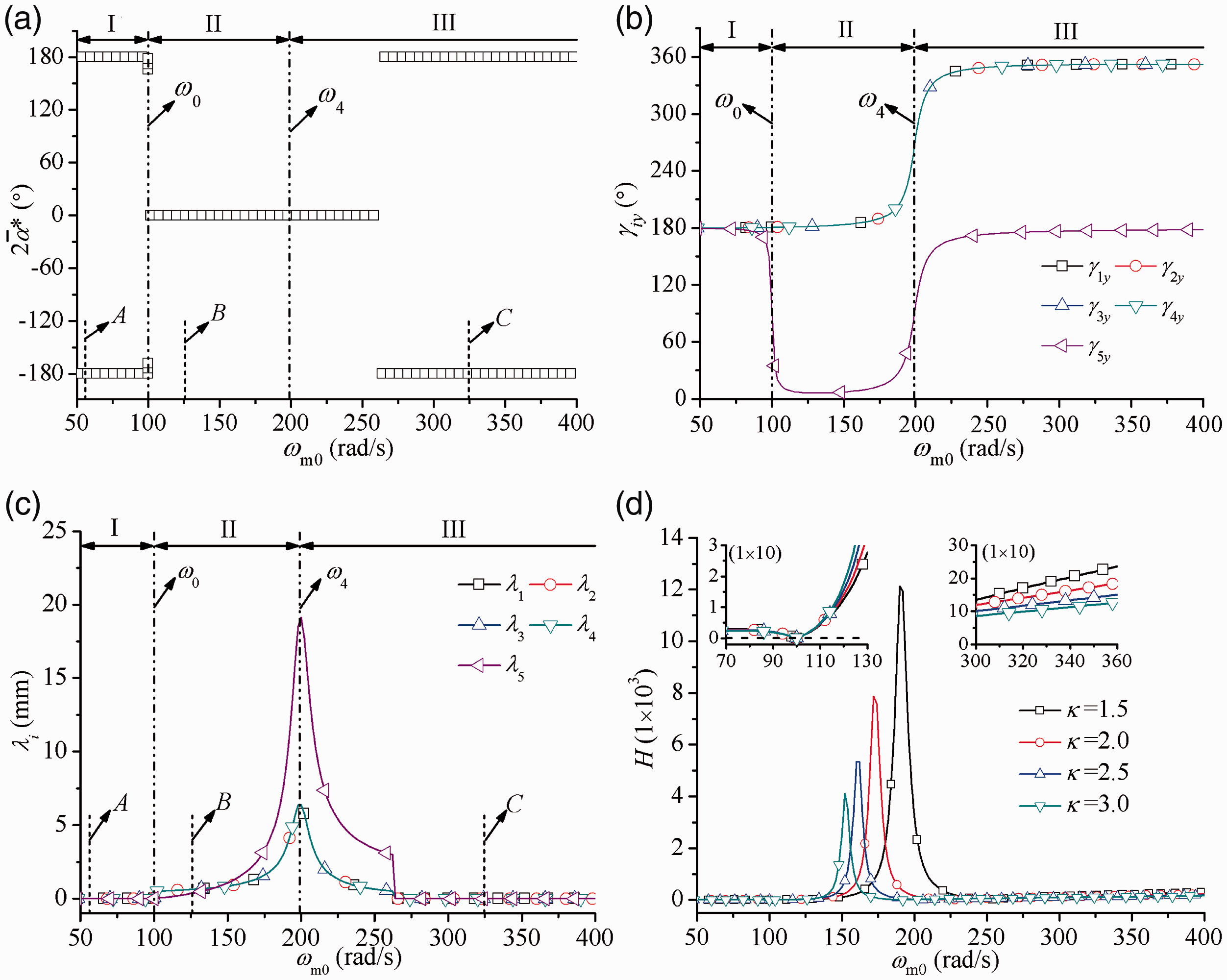
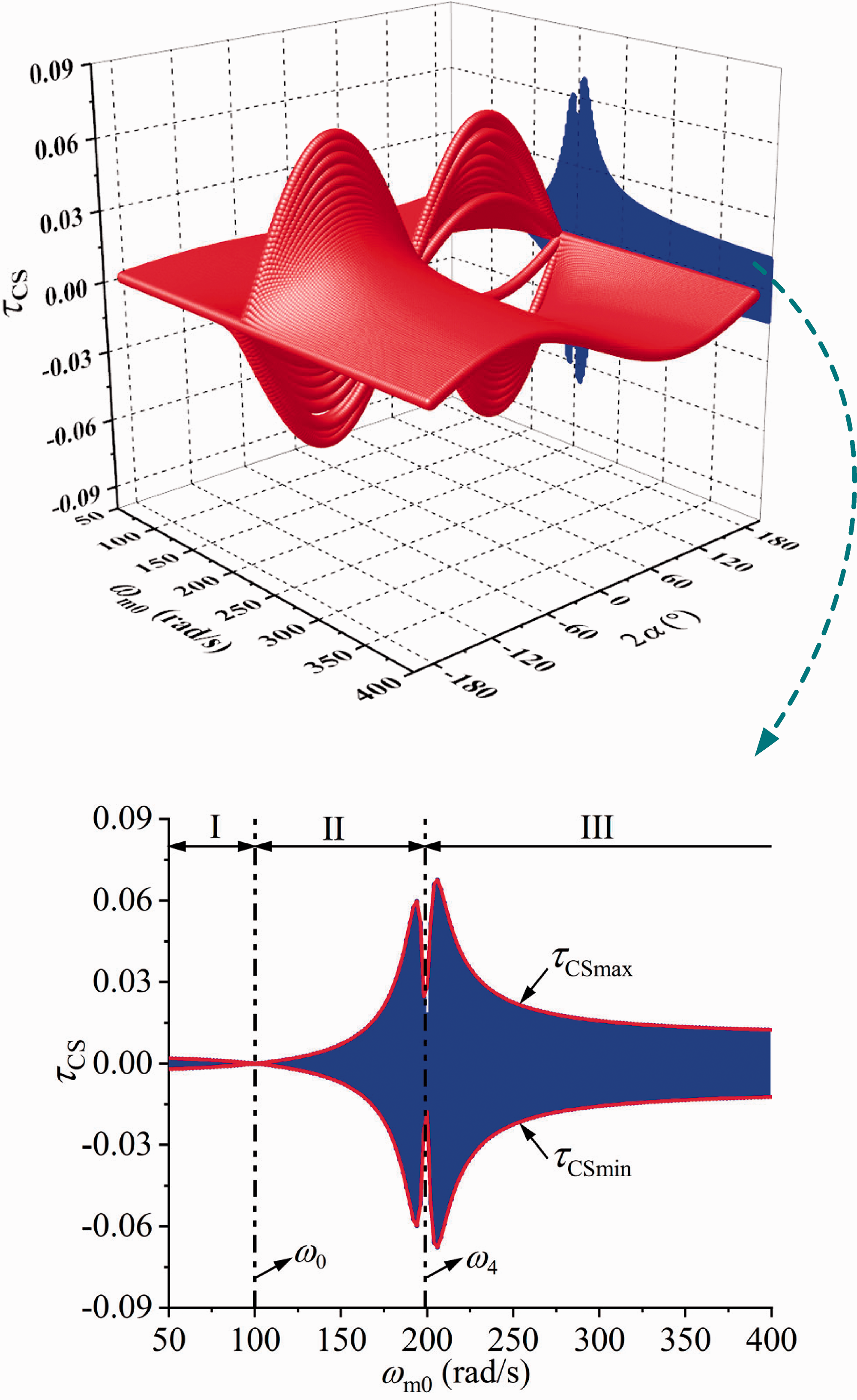
As shown in Figure 3, the relationship between (being as the difference of dimensionless effective load torque between two exciters) and (the operating frequency of the system) with the different values of can be obtained directly. And the tendency of the coefficient of synchronization ability denotes the system can easier realize synchronization and increase with the increasing . From the enlargement of the projection, we can obtain the range of from to , and there exists the relative smaller absolute value of corresponding to the two natural frequencies of the system, in this case, the system realizes synchronization difficultly. Besides, the system can easier realize synchronization in super-resonant region of than that in sub-resonant of it. Being contrary to what is shown in Figure 3, the resonant point of corresponds to the maximum of the stability ability in Figure 2(d); in this case, the ability of synchronization, however, reaches its minimum.
Difference of dimensionless effective load torque between two exciters.
Simulations
To further verify the feasibility of results of the previous theory and numerical qualitative discussions, another numerical simulation method called the fourth order Runge–Kutta routine is directly applied to equation (1). Here, taking , the other parameters of the system are the same as that in Numerical qualitative analyses on characteristics of the system section except for the stiffness of springs. A disturbance with is added to the motor 2 at 30 s in Region II or 80 s in other regions. To describe the simulation points clearly, we introduce the value of , which is the ratio of the operating frequency to the natural one, and its expression is in form
The different dimensionless values of zk can be obtained by setting the different values of the stiffness of springs, and the detailed simulation results with different zk are given as follows.
Simulation results in Regions I and III of Figure 2
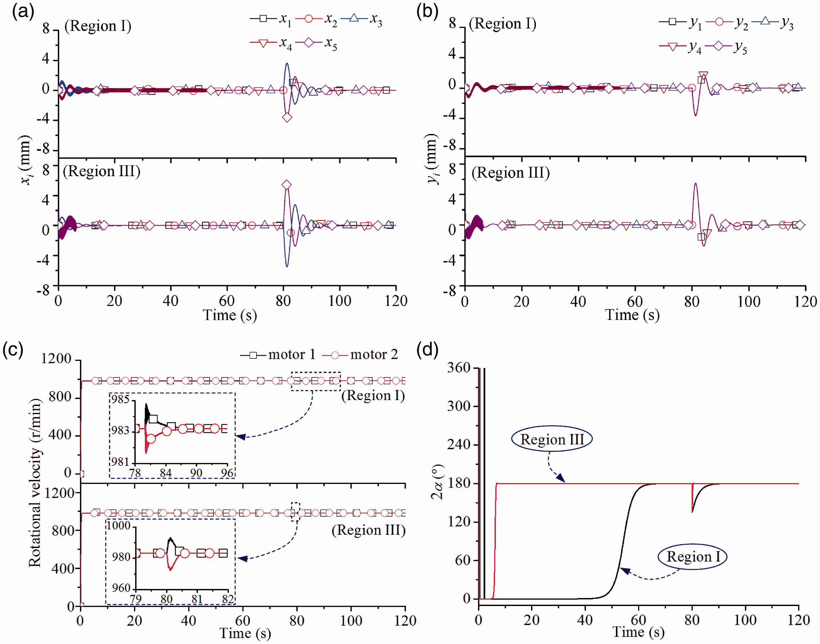
We set as and , the corresponding natural frequencies of the system are calculated to be and . From the Region I of Figure 4(c), one can see that the synchronous rotational velocity of the system is 983 r/min (i.e., ωm0= 102.6 rad/s), we can calculate that the frequency ratio , which is in the sub-resonant region with respect to , corresponds to the point A in Figure 2(a) and (c). The detailed results are seen in the Region I of Figure 4.
Simulation results of the Regions I and III: (a) displacements of the five RFs in x-direction, (b) displacements of the five RFs in y-direction, (c) rotational velocities of the two motors, and (d) phase difference between the two exciters.
In Region I of Figure 4, we can see that the system begins to be in the synchronous and stable state after 62 s, and in this case, the synchronous and stable rotational velocity is 983 r/min, the stable phase difference , see Figure 4(c) and (d). These results are well in agreement with the point A in Region I of Figure 2. A disturbance of is added to motor 2 at 80 s, the system returns its previous stable state after a short time (about 15 s) fluctuations, by which the strong stability of the system is indicated.
Then, we set as and , the values of the natural frequencies of the system can be obtained: and . From the Region III of Figure 4(c) and (d), in the steady state, one can see that the synchronous rotational velocity is 983 r/min (i.e., ωm0= 102.6 rad/s), and the phase difference between two exciters is . The corresponding frequency ratio , which is in the super-resonant region with respect to , corresponds to the point C in Figure 2(a). Similarly, in order to examine the strong stability of the system, a disturbance of is added to motor 2 at 80 s, and the system also returns its previous stable state after a short time (about 15 s) fluctuations. The detailed results are seen in the Region III of Figure 4.
From Figure 4(a) and (b), we can note that the displacements of the system in x- and y-directions are all zero in the steady state of the Regions I and III, this is because that the stable phase difference of two exciters is stabilized in the vicinity of , and in this case, the exciting forces of two exciters are compensated with each other. In these two cases, the motion types of the system are about at rest, and these facts are in accordance with points A and C in Figure 2.
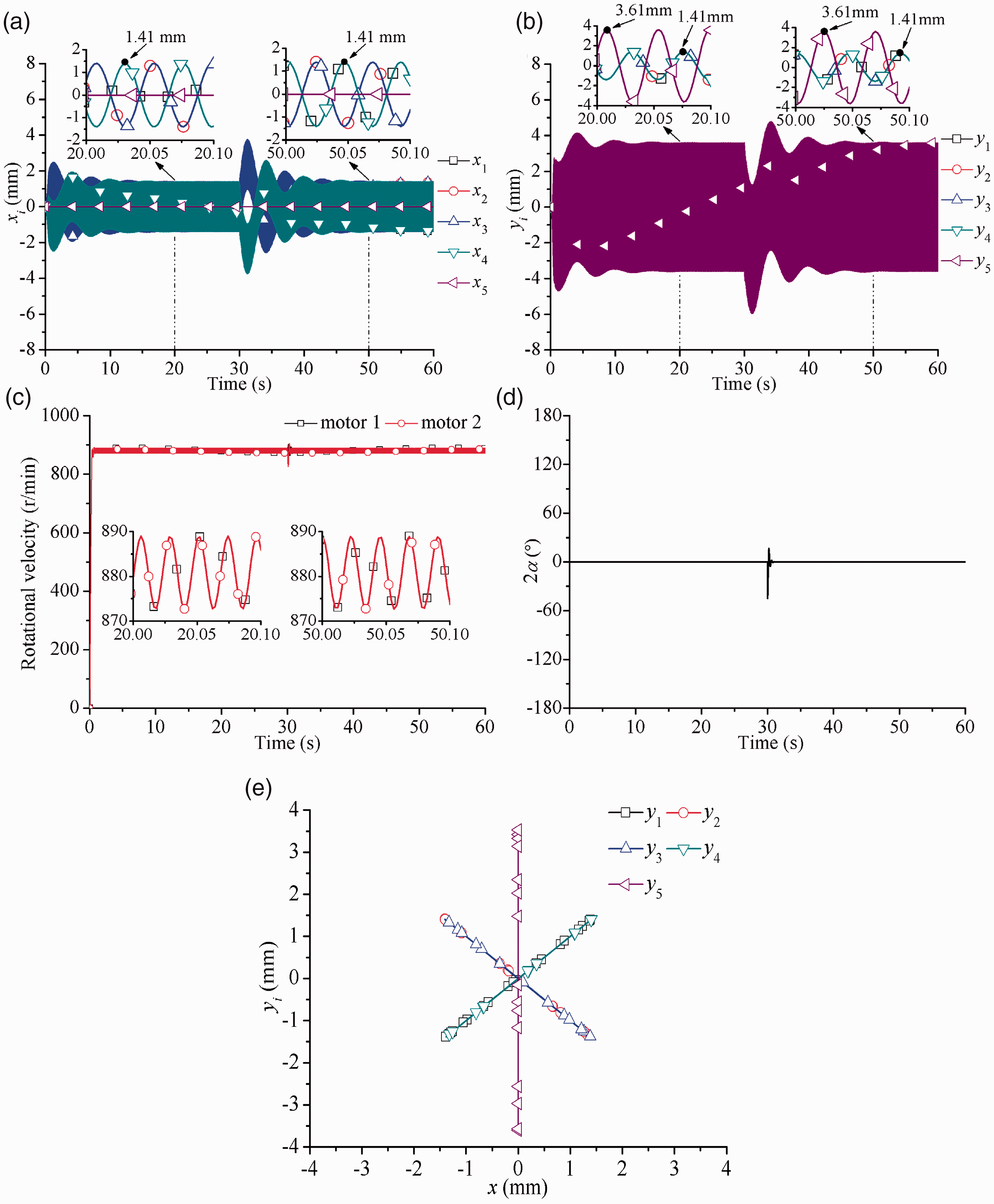
Here, the spring stiffness: and , the calculated natural frequencies of the system are and . Similar to Simulation results in Regions I and III of Figure 2 section, from Figure 5(c), we know that the synchronous rotational velocity is 881 r/min (i.e., ), so we can calculate , which qualitatively corresponds to the point B in Figure 2(a) and (c), and the detailed simulation results are as follows.
Simulation results of the Region II: (a) displacements of the five RFs in x- direction, (b) displacements of the five RFs in y-direction, (c) rotational velocity of the two motors, (d) phase difference between exciters 1 and 2, and (e) motion trajectories of the five RFs in the steady state.
Since the two exciters are identical, as well as the two driving motors, they reach their rated speed at the same time during the starting process, and the system implements synchronization and ensures a certain stable operating state in the steady state. At this time, the stable state of the system: the synchronous rotational velocity is 881 r/min, the stable phase difference of the two motors , see Figure 5(c) and (d), these are well in agreement with the point B in Figure 2(a) and (c). At 30 s, the motor 2 is subjected to a disturbance with , there are some small transient fluctuations in the steady state of the system, in this process, the disturbance of the motor 2 is overcome by the coupling torques of the system, and finally, the system returns its previous synchronous and stable state after a short time jamming transient process, which indicates that the system has strong stability.
Besides, the motion types, phase relationships and displacements of the system in the steady state are as follows:
In x-direction, the IRF1 and IRF2 are the linear vibration with the opposite phase in x-direction, as well as the lower IRF3 and IRF4, meanwhile, the ORF reflects no vibration in x-direction, see Figure 5(a) and (e).
For y-direction, four IRFs are the linear vibration with the same phases, and the motion type between four IRFs and the isolation ORF is the relative linear motion with the opposite phases, see Figure 5(b) and (e).
As shown in Figure 5(a) and (b), the displacements of four IRFs in x-direction are the same as about 1.41 mm, while that of the ORF is 0, and in y-direction, the displacements of the former are the same as 1.41 mm, and that of the latter is about 3.61mm.
The above facts on phase relationships and displacements of the system are all well in agreement with what are illustrated in point B of Figure 2(a) and (c).
It should be pointed out that the displacement of the isolation ORF is greater than that of four IRFs, this is because that the mass of the former is relatively smaller than the total mass of the latter, we can decrease the response amplitude of the former by increasing its mass to meet the more desirable isolative effect in practice.
In engineering, the working point of the system should be selected in Region II of Figure 2, and in this case, the greater vibration amplitudes of the relative linear motion with the same phases of the four IRFs in y-direction can be realized, while the vibrations in x-direction of the four IRFs are compensated with each other, and the energy is also saved due to the resonant effect.
Utilizing the characteristics in Region II of Figure 2, a new type of vibrating coolers/dryers or screening equipment can be designed. Under the help of the guide strip, the practical motion type of each IRF is linear motion along a certain angle of inclination relative to the horizontal direction, but their vibrating forces in x-direction are compensated with each other to obtain the ideal isolation effect, and in this case, the materials needing to be cooled or dried on the IRFs can move along the direction of the arrowhead in Figure 1. The number of the IRFs can be increased to further prolong the moving time of the materials on it, by which the cooling/drying effect is improved. This type of machine corresponding to the present dynamical model has many advantages such as the compact structure, energy saving, ideal isolation effect, and low noises.
Conclusions
The following conclusions are stressed:
To ensure the synchronous and stable operation of the system, the theoretical conditions of implementing synchronization of the two exciters, and the stability condition of the synchronous states must be satisfied first. The former is mainly determined by the characteristics of the driving motors, while the latter is dependent on the structural parameters of the system.
The resonant regions of the system are divided into three regions by the two natural frequencies and , in regions of and the first narrow range of super resonant region with respect to , the phase difference between two exciters is stabilized in the vicinity of zero, and in this case, the relationship between the four IRFs and the ORF is the relative linear motion with the opposite phases in the vertical direction, while the total system reflects no vibration in the horizontal direction. When the phase difference between two exciters is stabilized in the neighborhood of in other regions, it causes the fact of no vibration of the system.
The relationship between the maximum of the difference of dimensionless effective load torque between two exciters and the operating frequency of the system can be obtained directly, see Figure 3. Especially at the resonant points of and , the values of the maximum are relatively smaller. However, the minimum of the ability of synchronization corresponds to the maximum of the stability ability at the resonant point of .
In engineering, the working point of the system should be selected in Region II of Figure 2, and in this case, the greater vibration amplitudes of the relative linear motion with the same phases of the four IRFs in y-direction can be realized, while the vibrations in x-direction of the four IRFs are compensated with each other, and the stronger stability of the system is realized.
Based on the present work, some new types of vibrating machines, such as vibrating cooling/drying fluidized beds and vibrating screens, can be designed. In this case, some advantages, such as compact structure by adopting the modular design of subsystems and using the combination of series and parallel among IRFs, energy saving, ideal isolation effect, and low noises can be realized.
Footnotes
Declaration of conflicting interests
The author(s) declared no potential conflicts of interest with respect to the research, authorship, and/or publication of this article.
Funding
The author(s) disclosed receipt of the following financial support for the research, authorship, and/or publication of this article: This work was supported in part by National Natural Science Foundations of China ( 52075085) and the Fundamental Research Funds for the Central Universities [N2103019].
ORCID iD
Xueliang Zhang
References
1.
KimYKimDJeongW.Dynamic modeling and analysis of a quad horizontal damper system for transient vibration reduction in top loading washing machine. J Mech Sci Technol2019; 33: 1123–1130.
2.
SunYUZhouJSGongD, et al. Vibration control of high-speed trains self-excitation under-chassis equipment by HSLDS vibration isolators. J Mech Sci Technol2019; 33: 65–76.
3.
HuygensC.Horologium Oscillatorium Sive De Motu Pendulorum Ad Horo-logia Aptato Demonstrationes Geometricae. Paris: F. Muguet, 1673.
4.
Van der PolB.A theory of the amplitude of free and forced triode vibrations. Radio Rev1920; 11: 701–710.
5.
BlekhmanIISorokinVS.On the separation of fast and slow motions in mechanical systems with high-frequency modulation of the dissipation coefficient. J. Sound Vib2010; 329: 4936–4949.
6.
BlekhmanIIFradkovALNijmeijerH, et al. On self-synchronization and controlled synchronization. Syst Control Lett1997; 31: 299–305.
7.
BlekhmanII.Synchronization in science and technology. New York: ASME Press, 1988.
8.
InoueJArakiYMiyauraS.Self-synchronization of mechanical system (multiple cycle). JSMET1981; 42: 103–110.
9.
WenBCFanJZhaoCY, et al.Vibratory synchronization and controlled synchronization in engineering. Beijing: Science Press, 2009, pp. 17–143.
10.
WenBCZhangHLiuSY, et al.Theory and techniques of vibrating machinery and their applications. Beijing: Science Press, 2010, pp. 142–184.
11.
BalthazarJMFelixJLPBrasilRM.Short comments on self-synchronization of two non-ideal sources supported by a flexible portal frame structure. J Vib Control2004; 10: 1739–1748.
12.
BalthazarJMFelixJLPBrasilRM.Some comments on the numerical simulation of self-synchronization of four non-ideal exciters. Appl Math Comput2005; 164: 615–625.
13.
FangPHouYJ.Synchronization characteristics of a rotor-pendula system in multiple coupling resonant systems. Proc IMechE, Part C: J Mechanical Engineering Science2017; 232: 1802–1822.
14.
FangPHouYJNanYH, et al. Study of synchronization for a rotor-pendulum system with poincare method. J Vibroeng2015; 16: 2681–2695.
15.
ChenXZKongXXZhangXL, et al. On the synchronization of two eccentric rotors with common rotational axis: theory and experiment. Shock Vib2016; Article ID 6973597.
16.
ZhangXLGuDWYueHL, et al. Synchronization and stability of a far-resonant vibrating system with three rollers driven by two vibrators. Appl Math Model2021; 91: 261–279.
17.
ZhangXLLiZMLiM, et al. Stability and Sommerfeld effect of a vibrating system with two vibrators driven separately by induction motors. IEEE/ASME Trans Mechatron2021 ; 26: 807–817.
18.
KongXXJiangJZhouC, et al. Sommerfeld effect and synchronization analysis in a simply supported beam system excited by two non-ideal induction. Nonlinear Dyn2020; 100: 2047–2070.
19.
KongXXChenCZWenBC.Composite synchronization of three eccentric rotors driven by induction motors in a vibrating system. Mech Syst Signal Process2018; 102: 158–179.
20.
KongXXWenBC.Composite synchronization of a four eccentric rotors driven vibration system with a mass-spring rigid base. J Sound Vib2018; 427: 63–81.
21.
Zhao CY, Zhu HT, Wang RZ, and Wen BC. Synchronization of two non-identical coupled exciters in a non-resonant vibrating system of linear motion. Part I: Theoretical analysis, Shock and Vibration 2009;16: 505–516.
22.
Ni ZH. Vibration Mechanics. Xi’an Jiaotong University Press, 1989 (in Chinese).