
Abstract
In order to verify that the vibration system driven by multi-eccentric rotors has multiple synchronous states, a model of three eccentric rotors horizontal installation of plane motion is established to study the coupling dynamic characteristics. Based on the average method of modified small parameters, the frequency capture equation is constructed to obtain the conditions of synchronous motion and vibration synchronization transmission. According to the synchronous conditions, the stability state of achieving synchronous motion is converted into the solution of balance equation of the synchronous torque. There are multiple solutions to the torque equation because of the non-linear characteristics of the vibration system driven by multi-eccentric rotors. Then the stability condition is used to estimate which of the solutions is stable. After substituting the parameters of the experimental machine into the above method, the curves of the phase difference and its stability coefficients of three eccentric rotors system are obtained numerically. Two experiments show that the selected synchronous state depends on the initial condition and external disturbance, and if the vibration synchronization transmission conditions are satisfied, three eccentric rotors can not only achieve vibration synchronization transmission of one motor with switching off the power but also that of two motors with switching off the power.
Introduction
Synchronization is a special phenomenon in nonlinear vibration system, which is also called frequency capture. 1 Since Huygens proposed a description of synchronization of two pendulums, a large number of scholars have been attracted to study synchronization on different objects. With their efforts, a lot of research results have been proposed, and they mainly focus on two aspects of the eccentric rotor (ER, also named exciter)2–6 and pendulum.7–10 In these results, synchronization of ERs is one of the greatest engineering significance.1,2 That is divided into two main aspects, the former is the vibration suppression, such as synchronization of gas turbine engines with multiple shafts, which is not expected to occur because of the destruction of the large amplitude. 11 And the latter is the vibration utilization; 1 on the contrary, it is expected to happen because the system can get the resultant force excited by ERs, which is also the research object of this paper.
The study of synchronization theory of ERs started from Blekhman, 2 who not only gave the general definition and example design of synchronization 12 but also proposed one method of the separation of fast and slow motion to solve a number of synchronous problems. 13 Thereafter, the research team of Wen proposed the average method of small parameters to obtain the synchronous condition and its stability condition of the vibration system.14–18 By applying such synchronization theory to engineering, they designed a lot of vibration machines. In Zhao et al., 14 synchronization of two ERs rotating in the reverse direction of plane motion is proposed to design the line vibration feeder. In Zhang et al., 15 synchronization of two homodromy ERs of plane motion is proposed to design the elliptical vibration screen. In Zhao et al., 16 synchronization of two ERs with the cross-shaft ERs of spatial motion is proposed to design the vertical vibration conveyor. In Chen et al., 17 synchronization of two ERs with the common shaft of spatial motion is proposed to design the vibration mill.
Since synchronization theory of two ERs in the vibration system has been successfully applied in engineering, vibration machine has created significant production benefits. In order to satisfy the demand for large-scale development of industry, scientists began to develop the vibration machine driven by multi-ERs.18–20 However, the vibration machine driven by multi-ERs of utilizing vibration synchronization has never successfully been used in engineering. Although the relevant reasons are explained in Zhang et al.,18,20 the lack of experimental studies leads to the inability to fully understand the dynamic characteristics of the vibration system.
The key to study synchronization theory of the vibration system driven by multi-ERs is that the stable synchronous state of ERs must be comprehensively understood. This paper is an extension of the works in Zhang et al.18,20 Based on the method of average method of small parameters, some quantitative analyses about the synchronous state of three ERs in the vibration system will be given in this paper by numerical and experimental ways to further perfect the understanding of the dynamic characteristics of the vibration system.
In our paper, the vibration system driven by three homodromy ERs horizontally mounted on a single base of plane motion is used as a model to investigate the coupling dynamic characteristics when the system operates in super-resonance (more than three times natural frequency). The paper contains the following components: first, the electromechanical coupling equations of the system is given in “Synchronization characteristic of three ERs” section. Then, the synchronous conditions of synchronous motion and VST are deduced. After that, an analysis method of the synchronous state is proposed. In “Numerical results and discussion” section, numerical discussions corresponding to the theory are given to study the selected synchronous state. In “Experiments” section, two experimental results are presented to verify the effectiveness of the theoretical analysis. Finally, conclusions are presented briefly.
Synchronization characteristic of three ERs
Frequency capture equation
As shown in Figure 1, the dynamic model of the vibration system consists of a rigid body, a fixed base, springs, and three ERs. The springs connect the rigid body with the base. Three induction motors drive three ERs in the same rotational direction, respectively. The translational motions of the body are
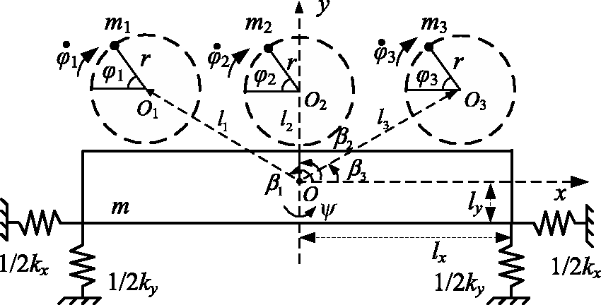
The dynamical model of the system.
Next, synchronization of three ERs in the vibration system will be analyzed by using the average method of modified small parameters. This paper only gives the critical conclusions obtained by the method of modified small parameters, and the detailed derivation process can refer to Zhang et al. 20 In order to better guarantee the readability of this work, the application process of the average method of modified small parameters is given in this paper, as shown in Figure 2.
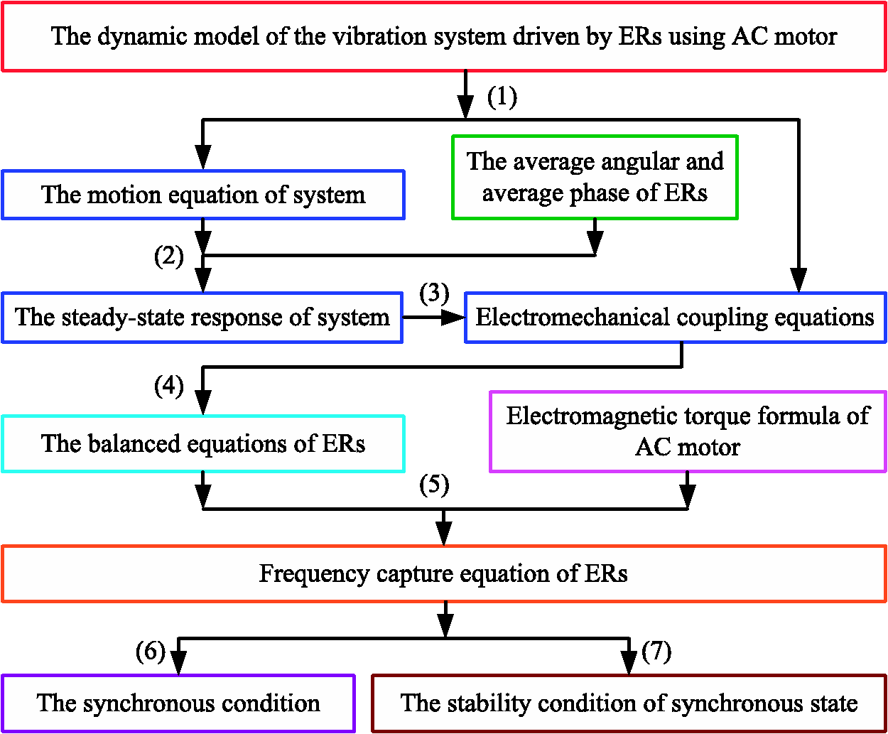
Flow diagram of the average method of modified small parameters.
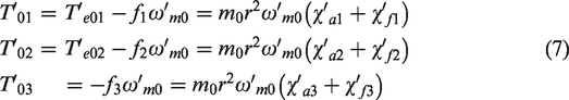
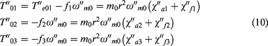
Step 1 in Figure 2, the motion equations of the system are obtained applying Lagrange’s equation. The electromechanical coupling equations of the system are given as follows
20
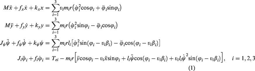
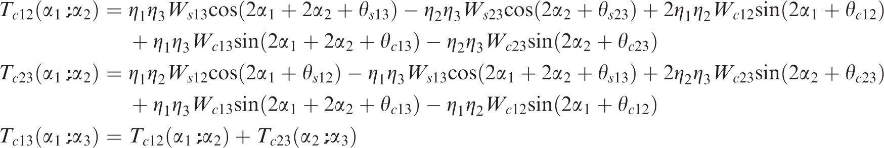
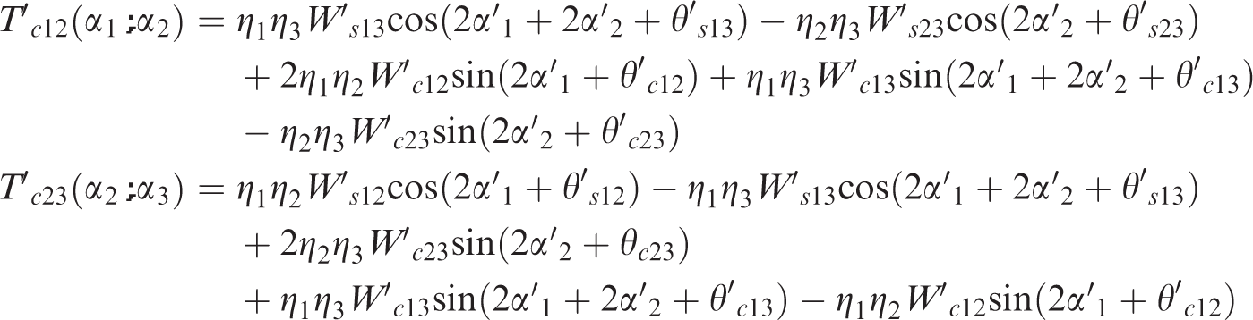
Steps 2 to 4 in Figure 2 are omitted, and step 5 is given directly. The frequency capture equation of three ERs is

Synchronous condition
Step 6 in Figure 2, if the synchronous motion of three ERs is achieved, the disturbing term

When three ERs operate in the synchronous state, the system distributes the load torques of three motors by adjusting the phase differences of three ERs, which are used to balance the difference of the output torque of three motors. Based on equation (3), the difference of the output torque (
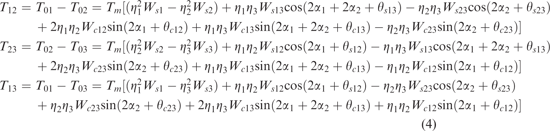
Equation (4) is simplified as

From equation (5), it can be seen that

In addition, equation (6) is the synchronous condition of three ERs in the vibration system.
When three ERs achieve the synchronous motion, if the power of one of three motors is switched off, the system may guarantee the synchronous motion of three ERs by vibration synchronization transmission (VST).14–17 Assuming that the power of motor 3 is switched off, the synchronous velocity of the system is


The same as above, the condition of VST under the case of two motors with power switched off is given as follows


Stability condition of the synchronous state
Step 7 in Figure 2, if the system satisfies the synchronous condition,

In equation (13),


If
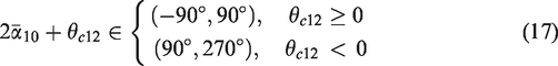
Based on the stability condition of the synchronous state, the ranges of the stable phase differences are
Numerical results and discussions
The synchronous condition and its stability condition have been given in the previous section. This section will present numerical results to propose a dynamic analysis method of the stable synchronous state. Based on the parameters of the test machine (it will be introduced in “Experiments” section), we make an appropriate hypothesis that it is completely symmetric, that is,
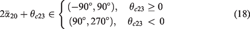
In Figure 3, the dynamic analysis method of the stable synchronous state is given as a flowchart. Combining the actual structure of the vibration machine,
Flow diagram of the theoretical analysis method of the stable phase difference.
According to Figure 3, some results are obtained. In Figure 4, all phase differences versus with
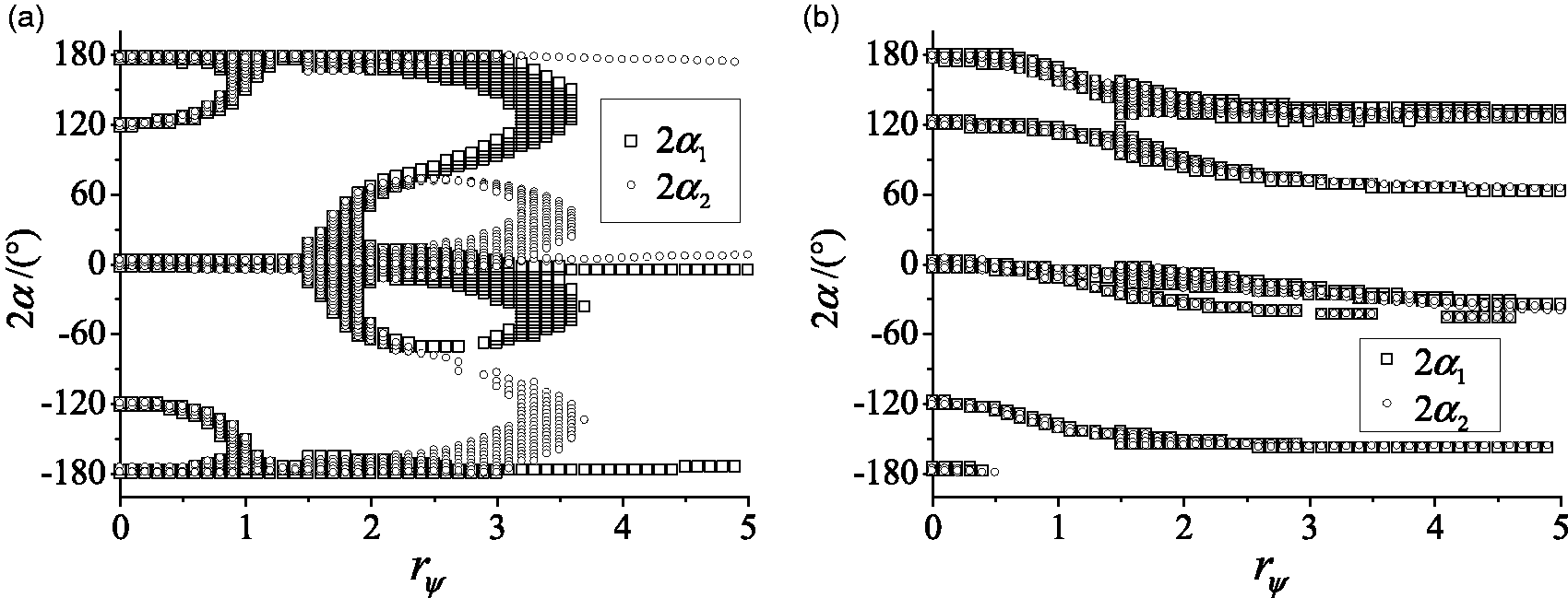
All phase differences versus with
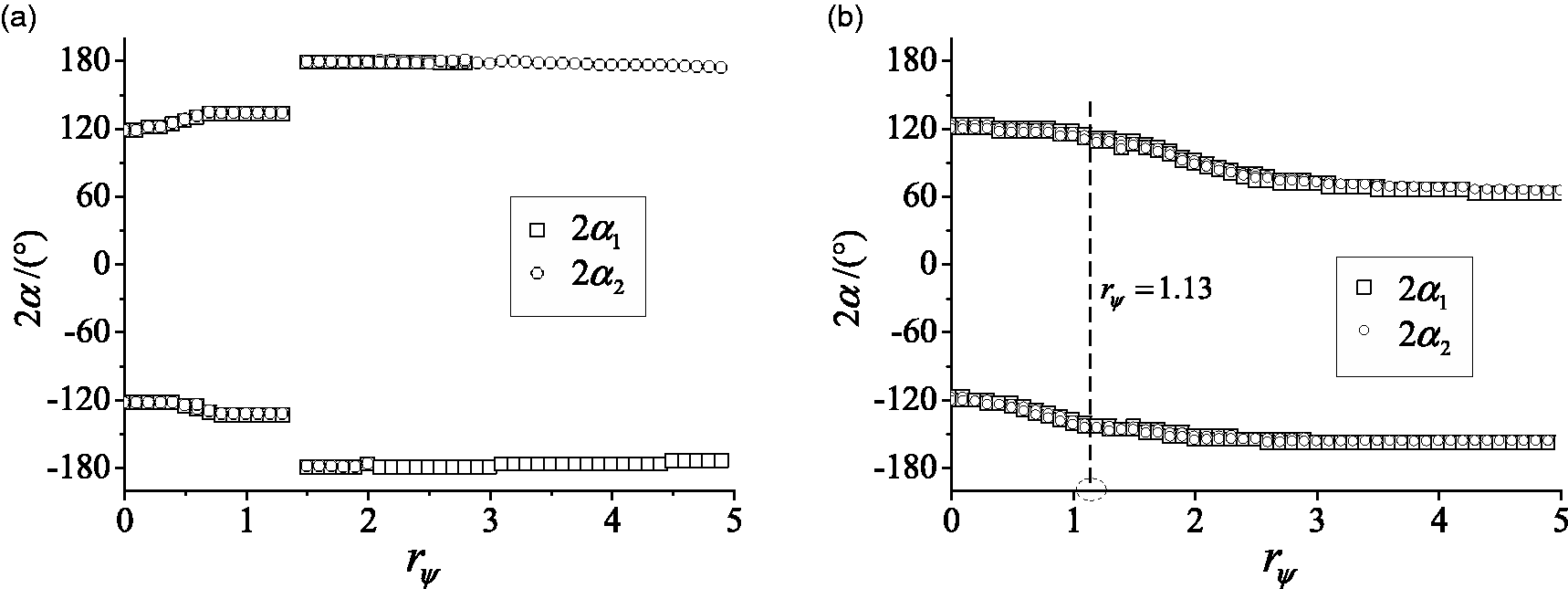
Stable phase differences versus with
Comparing to Figure 5, the stability coefficients of the synchronous state are shown in Figure 6. When
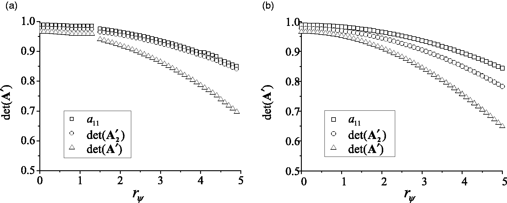
Stability coefficients of synchronous state versus with
Experiments
In this section, we will verify the validity of the theoretical analysis and the numerical results of the above sections by comparing to the experimental results of a vibration machine. Figure 7 shows the mechanical components of the vibration machine, which consists of three vibration motors: the rigid frame, the springs, and the fixed base. Nos. 0 and 1 represent the positions measured by the acceleration sensors (INV9832-50), and No. 2 represents the reflective stripe used for the photography. The rotational velocities of three motors and the phases of three ERs are measured by the hall sensors (NJK-5002C). All acceleration signals in the vertical and horizontal directions, velocities of motors, and phases of three ERs are collected by the data acquisition equipment (INV306DF), as well as the phases of three ERs are recorded by the high-speed camera (Y3C,4GB/2000 fps), while three motors operate in 45 Hz power supplied by Siemens inverters. The detailed experimental process is shown in Figure 8.
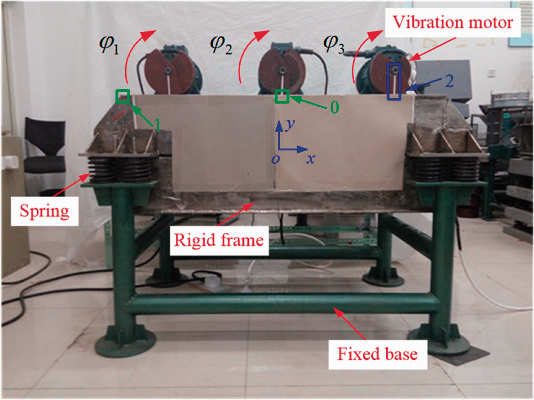
Vibration machine driven by three ERs with the horizontal linear installation.
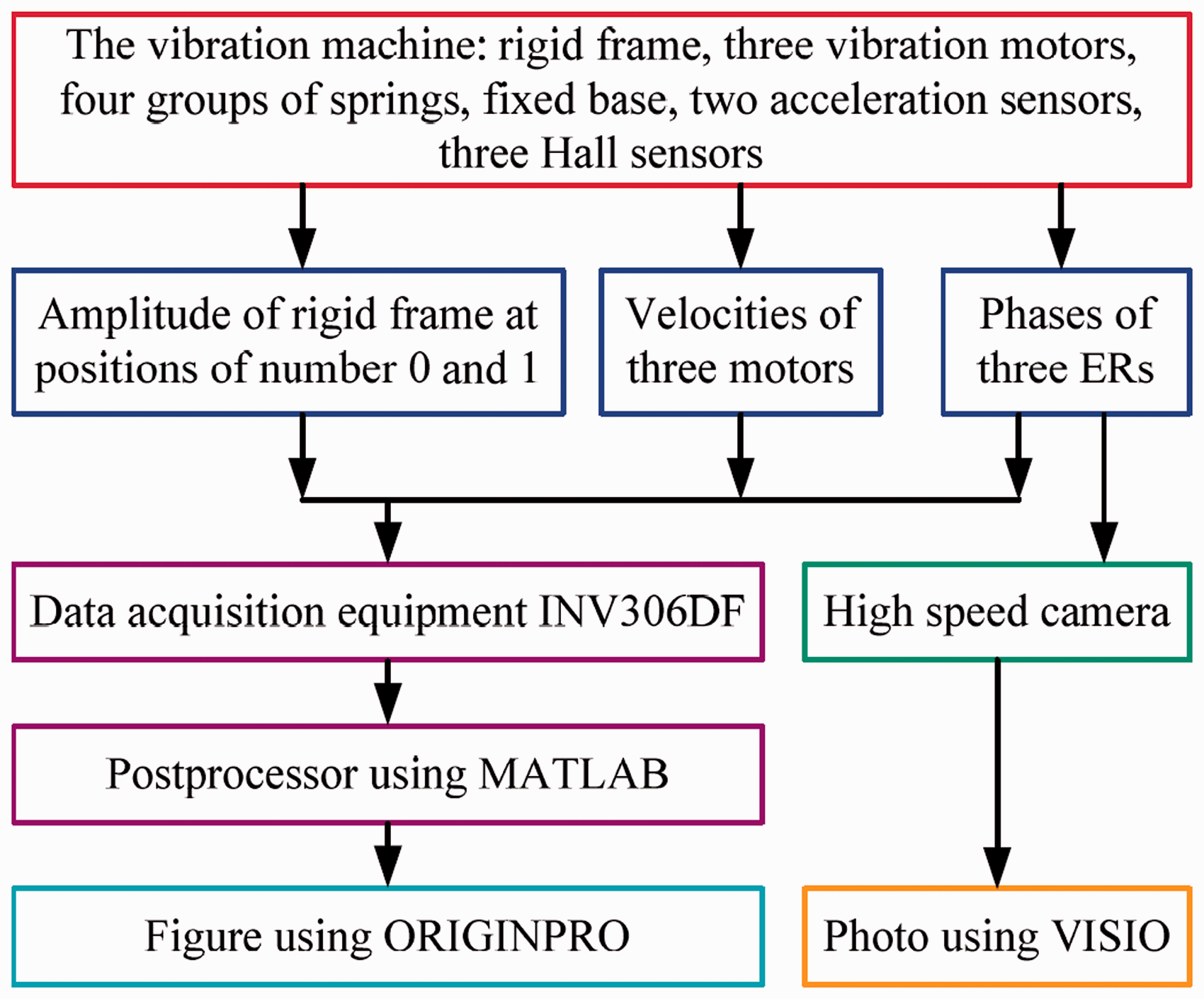
Flow diagram of experimental progress of vibration machine.
Due to the structural constraints, this machine can only verify the stability ranges of the phase differences of
As shown in Figure 9,
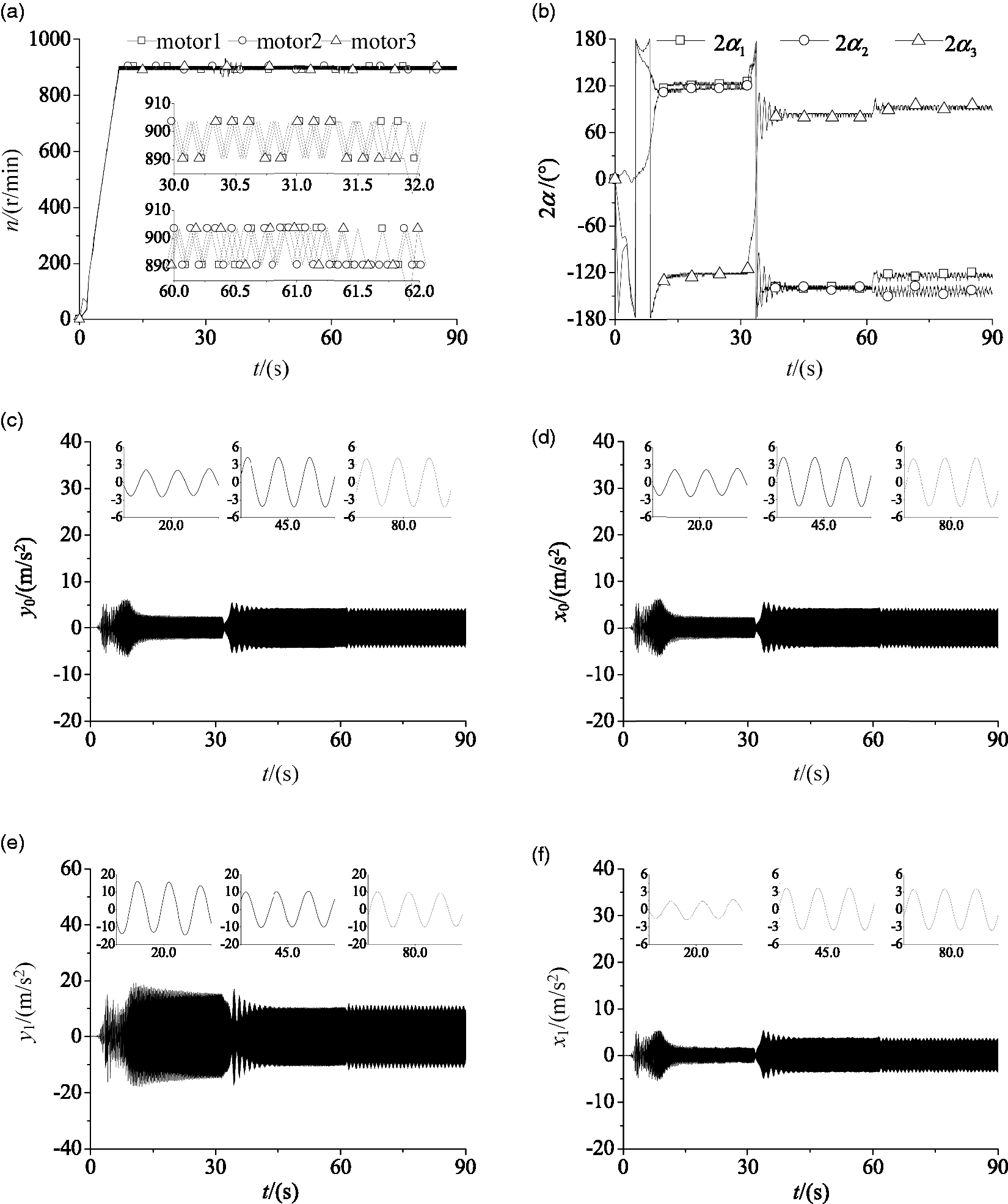
The first experiment results of the vibration system operating in super resonant,
When the power of motor 3 is switched off at the time of 30 s, the vibration system begins to operate in the state of VST. Due to the strong mechanical characteristics of AC motor, the synchronous velocity changes very little in this state, and it is about 895 r/min. However, the phase differences change greatly, which change from one state to another state,
In order to study this phenomenon of VST, two of three motors are switched off the power at the time of 60 s. As the power supply of motor 2 is switched off, the vibration system enters the same motion state of VST with different phase differences. Due to only one motor provides energy, the synchronous velocity decreases slightly, and it is about 892 r/min. And the phase differences are
In order to more easily observe the instantaneous phase of three ERs in the process of the synchronous motion, the high-speed camera is used to capture pictures at 50 Hz. Six pictures in one rotational period are used to verify the accuracy of the data acquisition instrument. Figure 10 shows the first synchronous state of three ERs when they are simultaneously powered in 45 Hz. The values of the phase difference are basically consistent with the data acquisition instrument. For the calculation of the phase difference, we usually use the form of less thanπ, so as to determine which rotor is the fast motor, which rotor is the slow motor. Hence,
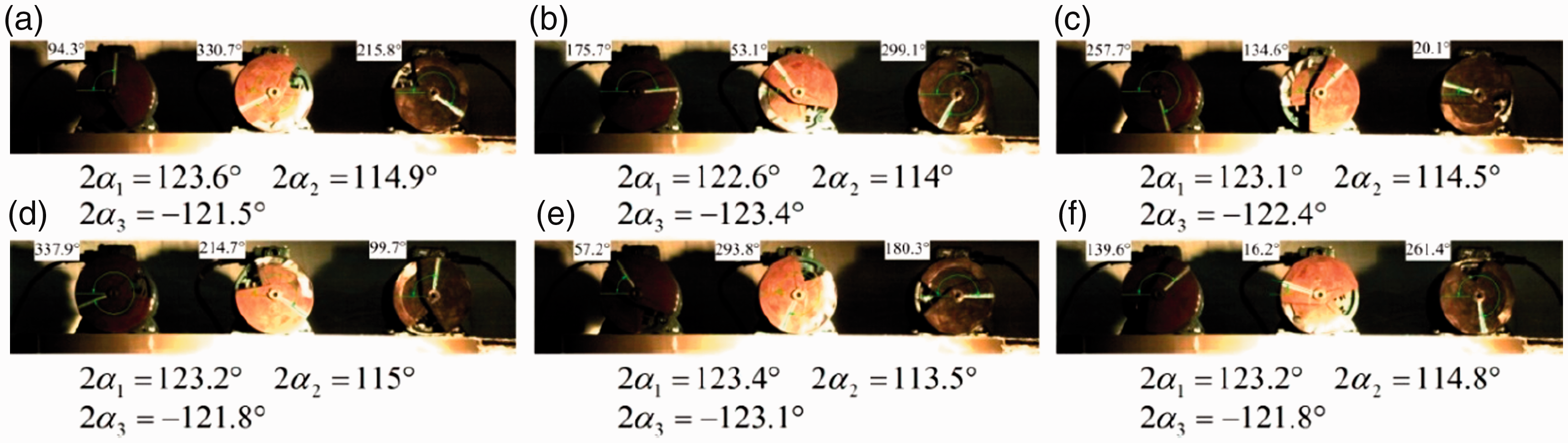
Phases recorded of first experiment by the high-speed camera.
As shown in Figure 11, the second group of experiments is obtained in accordance with the experimental scheme and the structural parameters of the first group of experiments. It is remarked that the vibration system selects another synchronous state in the second group of experiments, and the synchronous velocity is about 896 r/min, the phase differences are
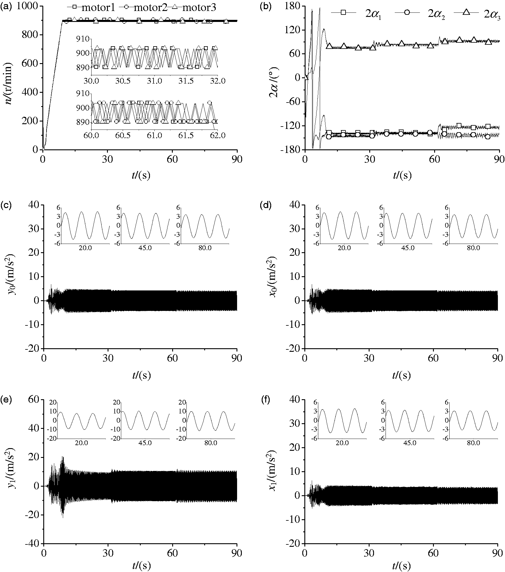
The second experiment results of the vibration system operating in super resonant,
When the power of motor 3 is switched off at the time of 30 s, the phase differences do not choose another synchronous state. The phase differences are kept with the same synchronous state in the process of VST. The state of VST is consistent between the time period from 30 to 60 s. Due to only one motor provides energy, the adjustment amplitude of the phase differences is more obvious than the first 60 s. The experimental method of switching off the power of motor can not only verify VST, but also can be regarded as a disturbance to the vibration system. Therefore, it can be concluded that the selected synchronous state of the vibration system depends on the initial condition and the external disturbance. From these two experiments, they show that the synchronous state of the second experiment is easier to satisfy the force balance when the vibration system runs in VST.
Figure 12 shows the second synchronous state of three ERs by using the high-speed camera at 50 Hz to capture pictures. The values of the phase differences are basically consistent with the data acquisition instrument.
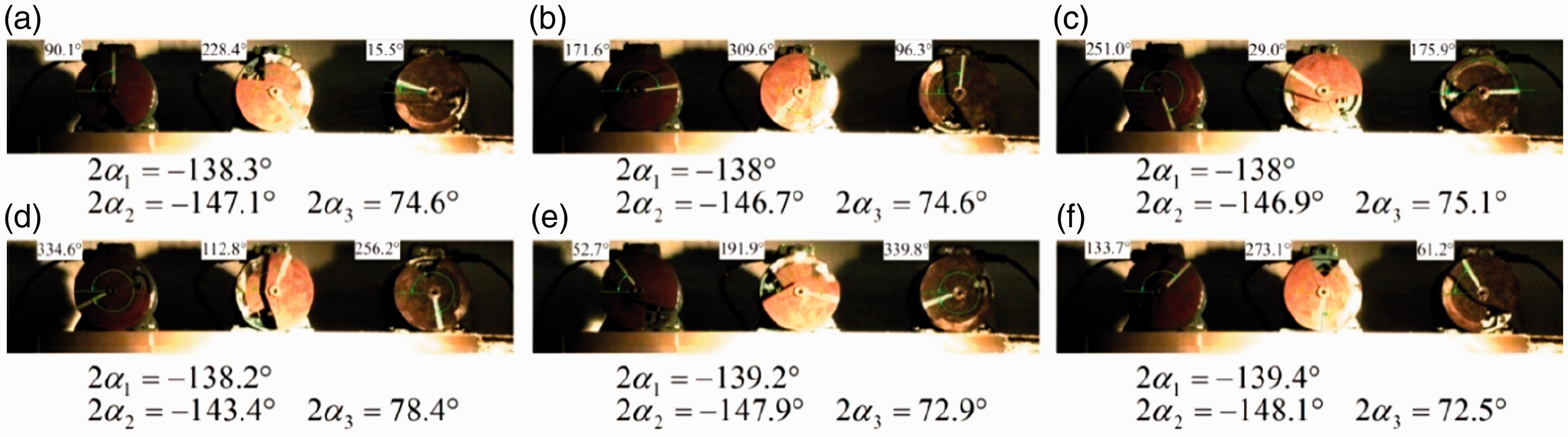
Phases recorded of second experiment by the high-speed camera.
To sum up, three ERs run in the out of phase motion of two synchronous states because of the motionless requirement of the vibration system, which causes the motion that is close to the motionless state. The motionless requirement reflects the minimum potential energy principle. Only when all the unbalanced forces cancel out each other can the motionless be achieved, which determines the selection motion tendency of the vibration system. When a primal balance state is broken, the vibration system finds a new balance state to ensure the motionless tendency. Because the vibration system driven by three ERs has two synchronous states, the system prioritizes states that are easier to implement. Hence, the initial condition and the external disturbance are important for the selected synchronous state of the vibration system driven by three ERs.
Conclusions
In this research, synchronization of the vibration system driven by three-ERs of plane motion is investigated. According to the synchronous conditions of the vibration system, a theoretical analysis method is proposed to analyze the synchronous state. The curves of the phase differences and their stability coefficients are obtained by substituting the experimental parameters into this method. By comparing these curves with the experimental data, the correctness and validity of the theoretical analysis method are proved. The results are given as follows:
Theoretical analysis explains that the vibration system driven by three-ERs has multiple synchronous states. Experiments also prove that when If the conditions of VST are satisfied, three ERs can not only achieve VST under the condition of one motor with switching off the power but also that of two motors with switching off the power. When
Footnotes
Declaration of conflicting interests
The author(s) declared no potential conflicts of interest with respect to the research, authorship, and/or publication of this article.
Funding
The author(s) disclosed receipt of the following financial support for the research, authorship, and/or publication of this article: this work is supported by the Fundamental Research Funds for the Central Universities (Grant No. N172303011), and Key Laboratory of Vibration and Control of Aero-Propulsion System Ministry of Education, Northeastern University (Grant No. VCAME201704).