
Abstract
Improving the surface integrity of laser cladded layer via burnishing is an important research topic in remanufacturing field. However, the initial surface roughness condition induced by mechanical machining generates great influence on the strengthening mechanism of subsequent burnishing. In this study, the effects of ultrasonic-assisted burnishing (UB) and ultrasonic-assisted warm burnishing (UWB) on the surface integrity of laser cladded layer were analyzed when treated on different surface conditions obtained by turning with different feed parameters. The results indicated that both the UB and UWB treatments would cause great improvements in microhardness, surface roughness including height and functional parameters, and residual stress of the laser cladded layer when compared to those by turning. First, the severe plastic deformation in UB and UWB treatments counteracted the thermal softening effect in turning process, so that the machined surface could maintain high hardness. Second, UB treatment reduced the roughness by 70% compared with turning, while the surface roughness after UWB treatment was even 30% lower than that obtained by UB. Third, the tensile residual stress shifted to deep compressive state by both UB and UWB treatments, though the thermal load in UWB generated a negative effect on generating compressive residual stress. According to the surface integrity evaluation results by radar diagrams, turning with feed f = 0.2 mm/r and UWB is preferred in machining of the laser cladded layer for enhanced surface integrity. On the basis of this research, it is expected to achieve the purpose of high-efficiency and high-quality cutting of the laser cladded layer.
Keywords
Introduction
Laser cladding is the using of high-energy laser beam to generate a cladded layer with special physical, chemical, and/or mechanical properties on the surface of substrate through rapid melting, expansion, and solidification, in order to make up for the lack of high performance of the substrate. On one hand, the Gaussian energy distribution of laser beam causes the metal powder to melt and accumulate to form arc-shaped tracks. Consequently, the cladded layer formed by multiple tracks has a rough contour.1,2 It is necessary to adopt mechanical machining method to improve the surface quality of the laser cladded layer. On the other hand, the hardness and wear resistance of the laser cladded layer can be very high by increasing the laser power and/or scanning rate within a certain range.3–5 As a result, the high hardness and wear-resistant of the cladded layer will inevitably increase the difficulty in machining this material.
Laser cladded materials belong to the category of difficult-to-machine materials. Improving the machinability and surface integrity of laser cladded layer is an important research topic. Grinding and cutting (such as turning, milling, etc.) are the most important means for machining of cladded layer. Precision grinding using super abrasive diamond wheels could produce a good surface finish (0.4 < Ra<1.0 μm) and appreciable surface integrity. 6 However, the material removal rate of the grinding process is extremely low. The cutting method can greatly improve the material removal rate, but there are disadvantages such as fast tool wear, poor surface quality, and the formation of tensile residual stress by the cutting process. 7 Therefore, scholars had carried out experimental researches around the optimization of cutting parameters in order to improve the surface integrity of laser cladded workpieces.8,9 Nevertheless, the surface roughness can reach ∼0.8 μm and the compressive residual stress can reach ∼−400 MPa by optimizing the cutting parameters, which is far from enough for the high-quality machining of high-performance parts.
Burnishing is a surface modification method by plastically deforming the workpiece surface. Nguyen and Le 10 investigated the influences of burnishing parameters on the surface roughness and microhardness. The results indicated an improved average roughness of 95.80%, and an improvement in microhardness of 45.44%, compared to pre-machined surfaces. El-Axir 11 found that the fatigue resistance of parts can be effectively improved as a result of the compressive residual stress induced by burnishing. Furthermore, the combination of turning and burnishing processes is confirmed to be feasibility for improving surface quality, energy reduction, and cost-effectiveness.12,13 In addition to significantly reducing roughness, the results also indicated that the energy consumption and production cost could be decreased by 20.15% and 17.19%.
In recent years, ultrasonic-assisted burnishing (UB) has developed rapidly and has been widely used in the field of surface modification because of the formation of deep compressive residual stress and surface work hardening, and decrease of surface roughness. Hence, the high-quality and high-efficient machining of the laser cladded layers is prone to be achieved with the combination of turning and UB treatment.
At present, the researches on UB are mainly limited to surface roughness and residual stress. On one hand, Liu et al. 14 established a mathematical model to predict the relationship between the process factors and surface roughness. The results indicated that the surface roughness Rt (i.e. the maximum height of the surface roughness profile) decreased with the increases of burnishing force and amplitude of ultrasonic vibration, while with the decrease of feed. Teimouri et al. 15 and Amini et al. 16 analyzed the effect of process factors on surface roughness Ra and hardness in ultrasonic-assisted ball burnishing aluminum 6061-T6 alloy through experimental research. The process factors were optimized in order to achieve maximum hardness and minimum surface roughness. The UB treatment is proved to be more conducive for microstructure modification and limited the elastic recovery of the surface when compared to conventional burnishing process without ultrasonic. However, the above researches evaluate the surface quality from the viewpoint of height parameters while ignoring the functional parameters of surface roughness, which will lead to a one-sided evaluation of the surface quality, and is also difficult to make reasonable predictions about service performance. Roughness evaluation using a bearing ratio curve (Abbot-Firestone curve), together with the functional parameters reduced peak height (Rpk), core roughness depth (Rk), and reduced valley depth (Rvk), is expected to connect the surface roughness with service performance.
On the other hand, Liu et al. 17 established a three-dimensional explicit nonlinear finite element model of ultrasonic-assisted ball burnishing process to relate the process factors with residual stress. The results confirmed that the use of UB treatment could generate deep compressive residual stress on the machined surface. In addition, Teimouri and Liu18,19 modeled and predicted the residual stress distribution in ultrasonic-assisted ball burnishing of aluminum 6061-T6 alloy aiming at maximizing the value of compressive residual stress. The effects of the burnishing parameters on residual stress were analyzed. However, the aluminum 6061-T6 alloy, as known to all, has low hardness and good plasticity. The difficulty in surface modification of materials with high hardness and low plasticity, which would weaken the tendency of plastic deformation in UB process, was not revealed.
Recently, warm plastic forming at medium temperature has become an attractive option for high-strength steels/alloys because it reduce the plastic deformation resistance than cold plastic forming and consumes less energy than hot plastic forming due to the decreased temperature. 20 In general, the temperature for warm plastic forming is considered to be in the temperature range above room temperature and below the complete recrystallization temperature which is generally considered to be 0.6 Tm (where Tm represents melting temperature). 21 As a matter of fact, the warm plasticity can help to reduce the plastic deformation resistance and burnishing load in UB process, which is prone to prevent the initiation and propagation of micro-cracks during the severe plastic deformation. Warm plasticity is also conducive to grain refinement and formation of dislocations. In addition, warm plastic deformation does not produce phase transformation, and has the equivalent dimensional accuracy comparing to that in room temperature. Hence, it is believed that the ultrasonic-assisted burnishing at medium temperature (i.e. ultrasonic-assisted warm burnishing, UWB) is more conducive for improving the surface properties than that at room temperature.
Li et al. 22 found that finer composition phases and thicker plastic deformation layer were generated by ultrasonic surface rolling in temperature range of 80°C–160°C comparing to that obtained by ultrasonic surface rolling at room temperature. Mo et al. 23 found that warm rolling in temperature range of 300°C–500°C could improve the plasticity and rolling workability of Fe–6.5wt%Si alloy compared to that obtained by cold rolling. Amanov et al.24,25 investigated the effect of ultrasonic nanocrystal surface modification (UNSM) in temperature range from room temperature to 800°C/700°C on the mechanical properties of Ti6Al4V and Inconel 690 alloys. For Ti6Al4V alloy, the hardness was increased by UNSM treatment with the increasing temperature. However, the residual stress shifted to tensile state when temperature exceeds 400°C, and phase transformation also occurred at 600°C and 800°C. For Inconel 690 alloy, surface roughness was increased by UNSM treatment with the increasing temperature, while the hardness was first increased with temperature increasing from room temperature to 300°C and then decreased at 700°C. Shen et al.26,27 investigated the role of UWB at 200°C on the surface properties of laser cladded layer. The results indicated that the UWB treatment was beneficial for further improvement in surface roughness, hardness as well as residual stress of the laser cladded layers.
Furthermore, mechanical machining processes are commonly conducted to remove the irregular surface profiles before burnishing. The initial surface roughness condition induced by mechanical machining, however, can generate great influence on the strengthening mechanism of burnishing. 28 The purpose of this research is to reveal the strengthening mechanism of UB and UWB processes on the laser cladded layers with considering initial surface conditions. Thus, the effects of UB and UWB treatments on surface integrity issues of laser cladded layers with different surface conditions by turning were comparatively analyzed. On the basis of this research, it is expected to achieve a high-efficiency and high-quality processing of the laser cladded layers, especially in terms of surface integrity.
Experimental details
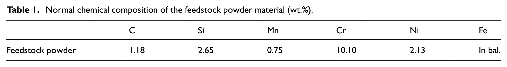
In this present study, Fe−based laser cladded layers (∼2 mm in thickness) were deposited on the AISI 1045 carbon steel rods with 120 mm in diameter and 300 mm in length. As shown in Figure 1, the substrate rod was mounted on a three-jaw chuck rotating around a horizontal axis, and was set in front of a laser beam as well as a lateral synchronous feed device which could be traversed horizontally. During the laser cladding, a semi-conductor laser conductor was utilized to generate the laser beam, which had an absorptivity of approx. 40% for Fe-based alloys. The other laser cladding parameters were listed as follows: laser power 3 kW, powder feed rate 450 g/min, scanning velocity 5.1 mm/s, footstep 7 mm, and carrier/shielding gas (N2) pressure 0.5 MPa. The nominal chemical compositions of the feedstock powder are listed in Table 1.
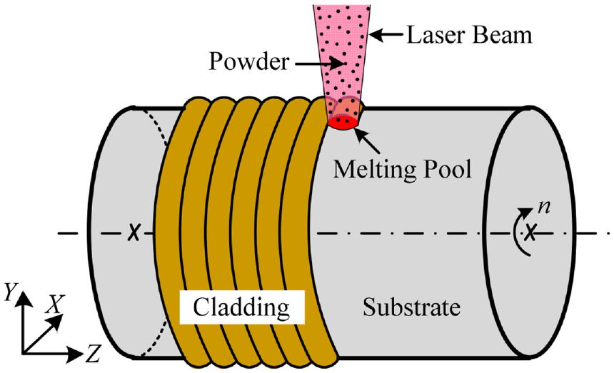
Schematic diagram of the laser cladding process.
Normal chemical composition of the feedstock powder material (wt.%).
The turning and burnishing experiments were conducted on the CA 6140 lathe, as shown in Figure 2(a) and (b). During turning, carbide coated insert (CNMG 120408 WF) was mounted on a right-hand tool holder PCLNR2525M12 (Sandvik Coromant) and then mounted on the turret of the lathe. During UB and UWB, a self-designed burnishing tool, as shown in Figure 2(c), was clamped on the turret of the lathe and made the feed motion. The burnishing ball of 6 mm in diameter is made of cemented carbide with a hardness of 92 HRA. In generally, an ultrasonic generator and an ultrasonic vibration transmission system including an ultrasonic transducer and a horn can be utilized to assist the burnishing.29,30 First, the ultrasonic generator installed in the control cabinet generates an AC signal (resonant frequency about 28 kHz), as shown in Figure 2(d). Then, the ultrasonic transducer converts the electrical signal into mechanical vibration of the same frequency, and the ultrasonic horn amplifies the vibration amplitude. At the meanwhile, a static load required for burnishing is provided by a spring. In such way, the static load from the spring combined with the periodic shock generated by the ultrasonic vibration acts on the surface through a burnishing ball. When UWB was conducted, especially, an inductance coil was utilized to heat the surface of the workpiece to required temperature. In this study, the temperature 400°C below 0.6 Tm, where Tm = 900°C for the laser cladded Fe-based alloy, was selected to realize warm plasticity. For this purpose, the induction coil was first energized until the temperature stabling at 400°C, which was measured by a contact thermometer. Then, the induction coil was set above the burnishing tool and close to the workpiece surface that to be burnished. At the meanwhile, the spindle of the machine tool and workpiece rotates in counterclockwise (looking from right to left). Therefore, the workpiece surface heated by the induction coil will be processed immediately by the burnishing tool.
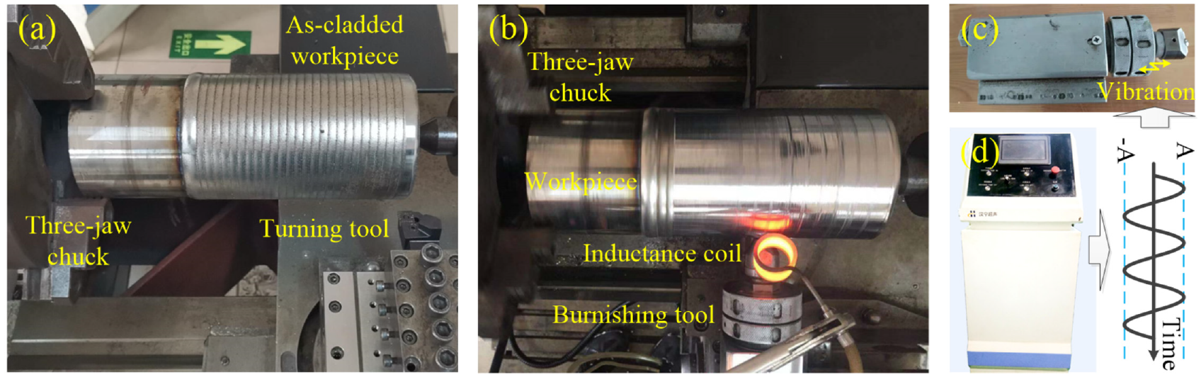
Experimental setups for (a) turning, and (b) ultrasonic-assisted burnishing, as well as the (c) self-designed burnishing tool, and (d) ultrasonic control cabinet.
It should be pointed out that the burnishing force will increase significantly, the surface quality will be significantly deteriorated, and the burnishing tool will also be damaged to some extent when burnishing with the burnishing tool (as shown in Figure 2(c)) in the absence of ultrasonic vibration. In the present study, therefore, the surface integrity of the laser cladded layer obtained by UB and UWB treatments was compared to that obtained by low plasticity burnishing (LPB) in order to reveal the significance of ultrasonic vibration. The results indicated that the average surface roughness after UB and UWB decreased by 47.4% and 63.2%, respectively, and the value of compressive residual stress increased by 18.9% and 21.1%, respectively, when compared to those by LPB through our previous study. 31 It is evident that the surface integrity can be further improved with ultrasound compared to without ultrasound. Therefore, this present study only compares the UB and UWB in order to study their strengthening mechanism on machined surfaces by turning with different feed parameters.
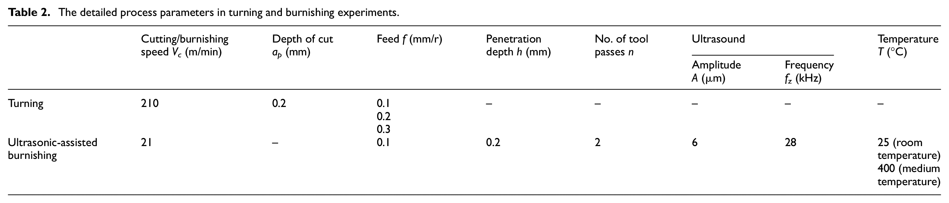
The detailed process parameters in turning, UB and UWB treatments are summarized in Table 2. The same burnishing setups except temperature was used to explore the strengthening mechanisms of UB and UWB on laser cladded layers with various initial surface conditions obtained by turning with different feeds. It is also worth noting that the burnishing speed is greatly reduced compared with the cutting speed used in turning. On one hand, the low burnishing speed provides sufficient time to heat the workpiece surface to be burnished and generate sufficient plastic deformation. On the other hand, a high burnishing speed can easily cause vibration, thereby destroying the quality of the burnished surface.
The detailed process parameters in turning and burnishing experiments.
After all of the processing was completed, residual stresses were recorded by a μ-X360 X-ray residual stress analyzer (Pulstec Industrial Co., Ltd.) through CuKα radiation which uses Debye Ring cosα method with the Fitting Lorentz approximation method. All samples were sent into the analyzer with an X-ray irradiation time of 90 s, X-ray tube current 1.00 mA, X-ray tube voltage 30.00 kV, X-ray incident angle 30.0°, and CuKα wavelength 2.29093 Å. The surface morphology was recorded by a Bruker white light interferometer (Contour Elite K). Evaluation of 3D surface roughness parameters (arithmetic mean height Sa parameter) was conducted according to ISO 25178. The functional parameters (reduced peak height Spk, core roughness depth Sk, and reduced valley depth Svk) of the surface profile were graphically evaluated according to the ISO 13565-2 standard using the Abbott–Firestone curve and bearing ratio curve. The microhardness distribution along the depth direction was also measured using a digital tester HXD-1000TMC at a load on the Vickers indenter of 50 gf and the dwell time of 15 s. All measurements were tested three times and an average of these values was taken as a response.
Results and discussion
Microhardness
The microhardness of the surface and subsurface is an important indicator to characterize the wear resistance of materials. In general, higher microhardness represents a better wear resistance of the material.
Figure 3 shows the microhardness profile induced by turning, UB and UWB treatments. Figure 3(a) indicates that the microhardness beneath the machined surface achieves the highest when turning with feed f = 0.1 mm/r. This is because the cutting tool is repeatedly machined in the work-hardening zone under the cutting condition of such a small feed, resulting in serious work-hardening, where the depth of the work-hardened layer is as high as 100 μm or more. However, the subsequent burnishing in the work-hardening zone results in an increase in temperature between the workpiece surface and the burnishing tool. 32 In addition, the recovery of microstructure and dynamic recrystallization are prone to occur as a result of large strain. Consequently, the microhardness on surface and subsurface by either UB or UWB is decreased when compared to that obtained by turning.
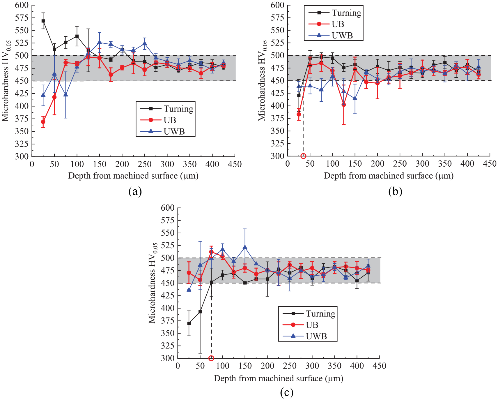
Microhardness profile of the laser cladded layer by UB and UWB following turning with different feeds: (a) f = 0.1 mm/r, (b) f = 0.2 mm/r, and (c) f = 0.3 mm/r (The shaded zone is the microhardness distribution of the as-cladded layer).
Figure 3(b) and (c) show that the microhardness beneath the machined surface is decreased when turning with feed f = 0.2 mm/r and f = 0.3 mm/r, respectively. The reason can be accounted to the effect of thermal softening under the role of the cutting temperature. Moreover, the thermal softening has a much greater significant influence on the machined surface as the feed increases. It can be seen from Figure 3(b) and (c) that the depth of softened layer is almost doubled when the feed increases from f = 0.2 mm/r (approx. 35 μm) to f = 0.3 mm/r (approx. 75 μm). Furthermore, the microhardness is increased by subsequent burnishing processes. This is a result of grain refinement under the mechanical loading applied by the burnishing ball. In addition, the subsequent burnishing will improve the microhardness more significantly with the increase of feed adopted in the previous turning process. This is because the surface residue on the machined surface by previous turning will increase as the feed increases, which will facilitate the plastic deformation in subsequent burnishing, thereby improving the microhardness.
As a matter of fact, the hardness (i.e. work-hardening) is a key factor in determining the wear resistance of the machined surface. 33 Figure 4 displays the degrees of hardening on the machined surface (the ratio of the microhardness of the machined surface to that of bulk material) induced by the turning and burnishing process. The results imply that the degree of hardening of the turned surface decreases by 26% as the feed increases from 0.1 to 0.3 mm/r, which should result in a significant reduction in the wear resistance of the machined surface. However, the subsequent burnishing causes an increase of the degree of hardening on the machined surface, which compensates for the negative effect of thermal loading induced by turning on the hardness. Thus, both the UB and UWB treatments can be utilized to improve the wear resistance of the laser cladded layer.
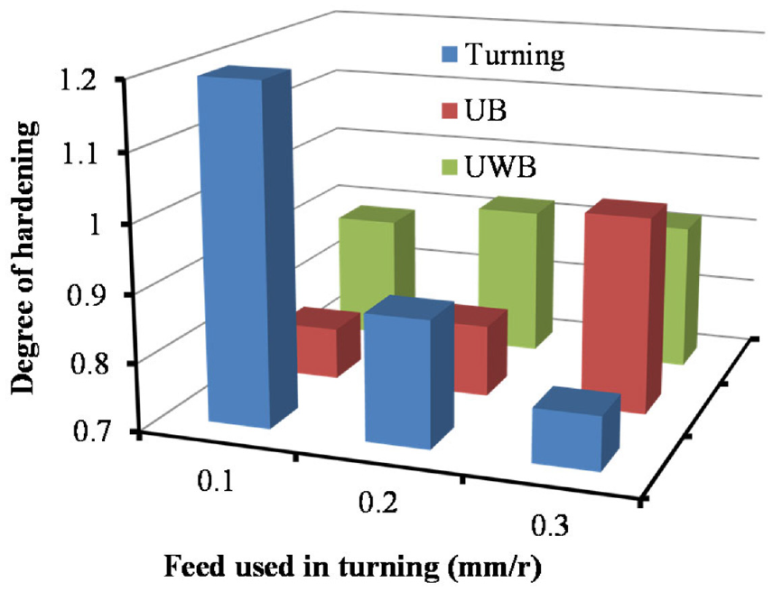
Effect of turning and subsequent burnishing on the degree of hardening of the machined surface.
Surface characteristics
It is well known that the origin of friction is due to the relative motion of two surfaces in contact with each other. Therefore, the surface characteristics must affect the friction behavior between the contacting surfaces. In this section, the surface characteristics will be analyzed from the perspectives of surface topography and surface roughness including height and functional parameters.
Surface topography and roughness profile
Table 3 summarizes the surface morphology maps of machined surface obtained by turning and subsequent burnishing. Tool marks are clearly obvious on surface topographies obtained by turning, and the distance between two neighboring tool marks is consistent with feed. The surface topographies are in wave shapes and the intersection of tool paths show the maximum position of peak value. Obviously, the surface roughness height induced by turning is relatively high.
Surface topography obtained by turning and subsequent burnishing processes.
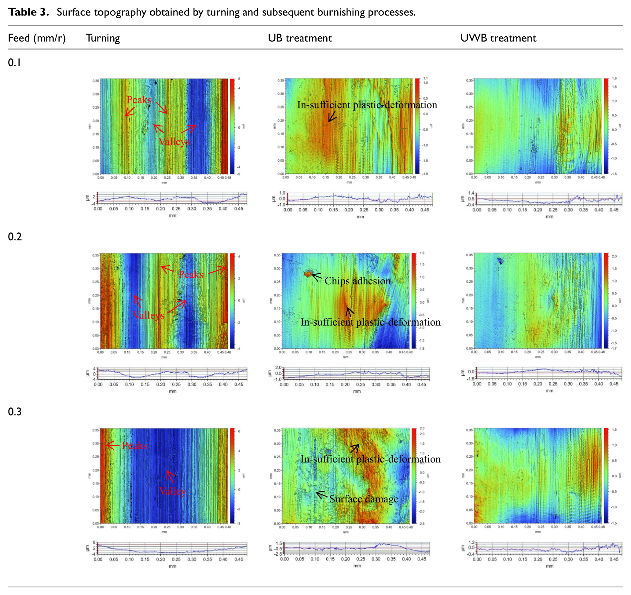
Burnishing is known as the procedure for severe plastic deformation and displaces the material from peaks into valleys by cold working. 34 Thus, the machined surface can be further smoothed by the UB and UWB treatments compared to that by turning. As shown in Table 3, the tool marks produced by previous turning disappear after the subsequent burnishing. However, the surface topography obtained by UB treatment exhibits partial rough because of insufficient plastic deformation which is caused by the high hardness of the material. It is also possible that cutting chips/debris will stick to the machined surface during the subsequent burnishing process. Moreover, the surface is prone to be damaged due to the problem of excessive folding when burnishing is performed on a machined surface by turning with feed of 0.3 mm/r. On the contrary, the surface topography by the UWB treatment can be relatively smooth as a result of sufficient plastic deformation.
The surface profiles along the feed direction further present the surface topography evolution by subsequent burnishing. The main findings were that the sharp peaks obtained by turning were transformed into blunt peaks with the peaks height reducing by the subsequent burnishing. In addition, the reduction of peaks height is more significant by UWB than that by UB treatment. Such changes in surface profiles reflect the severe plastic deformation history during the subsequent burnishing process.
Surface roughness parameters evaluation
The surface roughness by the turning and the severe plastic deformation behavior in subsequent burnishing are very closely related to the surface residual induced by turning. As shown in Figure 5(a), the surface residue induced by turning is determined by feed and tool nose radius. The surface residue area (A) induced by two adjacent feed movements can be derived based on equation (1).
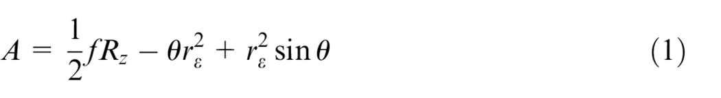
where,
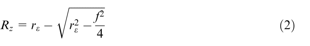
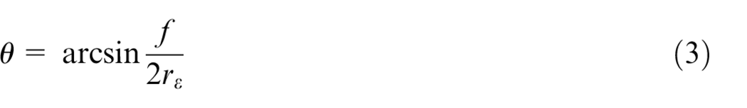
where f and rε represent the feed and tool nose radius, respectively, while Rz and θ represent the residual height and center angle, respectively. Figure 5(b) further shows the relationship between the surface residue and feed/tool nose radius. It can be seen that the surface residue increased with the increasing of feed and decreasing of tool nose radius. In this present study, hence, the initial surface for subsequent burnishing is obtained by turning with various feeds. On one hand, the increasing surface residue increases the surface roughness level. On the other hand, however, it is conducive to the severe plastic deformation in subsequent burnishing with surface residue increasing.
(a) Illustration of the surface residue on turned surface and (b) the relationship between surface residue and feed/tool nose radius.
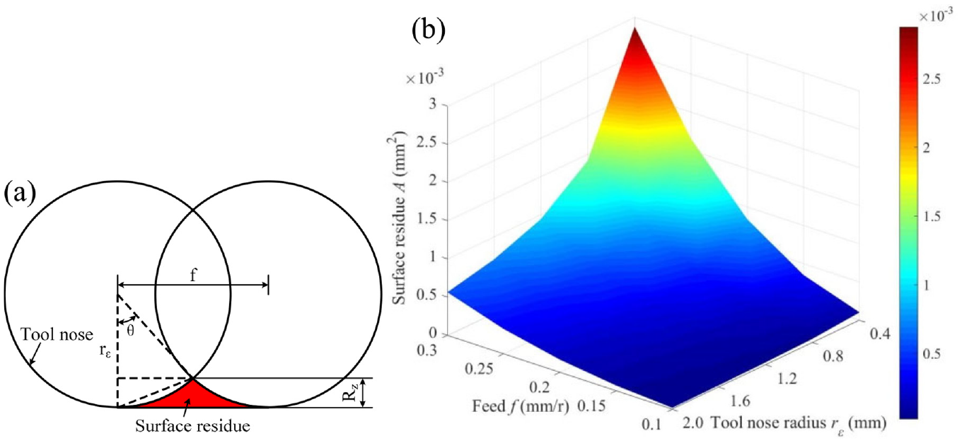
The areal arithmetic surface roughness (Sa) was extracted from contour plots of surface topography for quantitative characterization of the machined surface quality. Figure 6 shows the evolution of areal surface roughness after turning and subsequent burnishing processes. The results show that the areal surface roughness of the machined surface by turning is increased with the feed increasing. The reason can be attributed from the perspective of geometric kinematics theory to the increase of surface residue on the machined surface as the increase of feed. 35
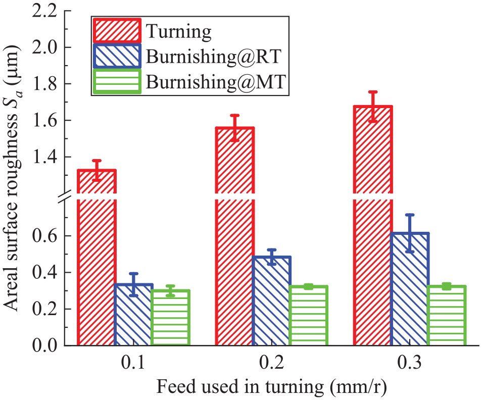
Areal surface roughness evolution of the laser cladded layer by different burnishing treatments following turning with different feeds.
Figure 6 also indicates that the areal surface roughness is significantly reduced by subsequent burnishing regardless of whether it is conducted at room or medium temperature. This is because the machined surface undergoes severe plastic deformation during the burnishing process, where the material at peaks of the surface roughness profile flows to valleys, thereby improving the surface quality of machined surface. With the assistance of temperature field, the plastic deformation resistance of the machined surface is weakened in the UWB treatment. Thus, the areal surface roughness is further reduced when compared to that by UB treatment, especially for turned surfaces obtained with large feeds. Another result is the improvement of areal surface roughness by subsequent burnishing is proportional to the surface roughness generated by previous turning, which is in consistence with other literatures.36,37 This reason is essentially determined by the surface residue induced by turning with different feeds. However, there is less difference in the surface roughness values after UWB treatment for turned surfaces obtained by any feeds. The reason attributes to the severer plastic deformation on the machined surface during the UWB treatment. The result confirms that the warm plasticity induced by temperature field is quite beneficial for plastic deformation, and in turn, for surface strengthening of the laser cladded layer with relative high hardness.
Besides the areal surface roughness, functional parameters of the machined surface can better reflect the service performance of the machined surface. The bearing ratio curve provides information about the shape of surface irregularities, that is why it is preferred to be used to analyze surfaces generated by means of multi machining processes.38,39 Moreover, the bearing ratio curve describes the distribution of material within the profile height and allows to anticipating the surface wear of part. The slope of this curve can be useful in determining how fast a surface will wear and the dimensional size change likely after wear-in stage. As shown in Figure 7, the bearing ratio curve is generated by plotting a curve at various depths. The bearing ratio curves of both turned and subsequent burnished surfaces are in the shape of degressive–progressive “S.” It is believed that the surfaces induced by turning have higher wear rate and result in a larger dimensional error after the wear-in stage.
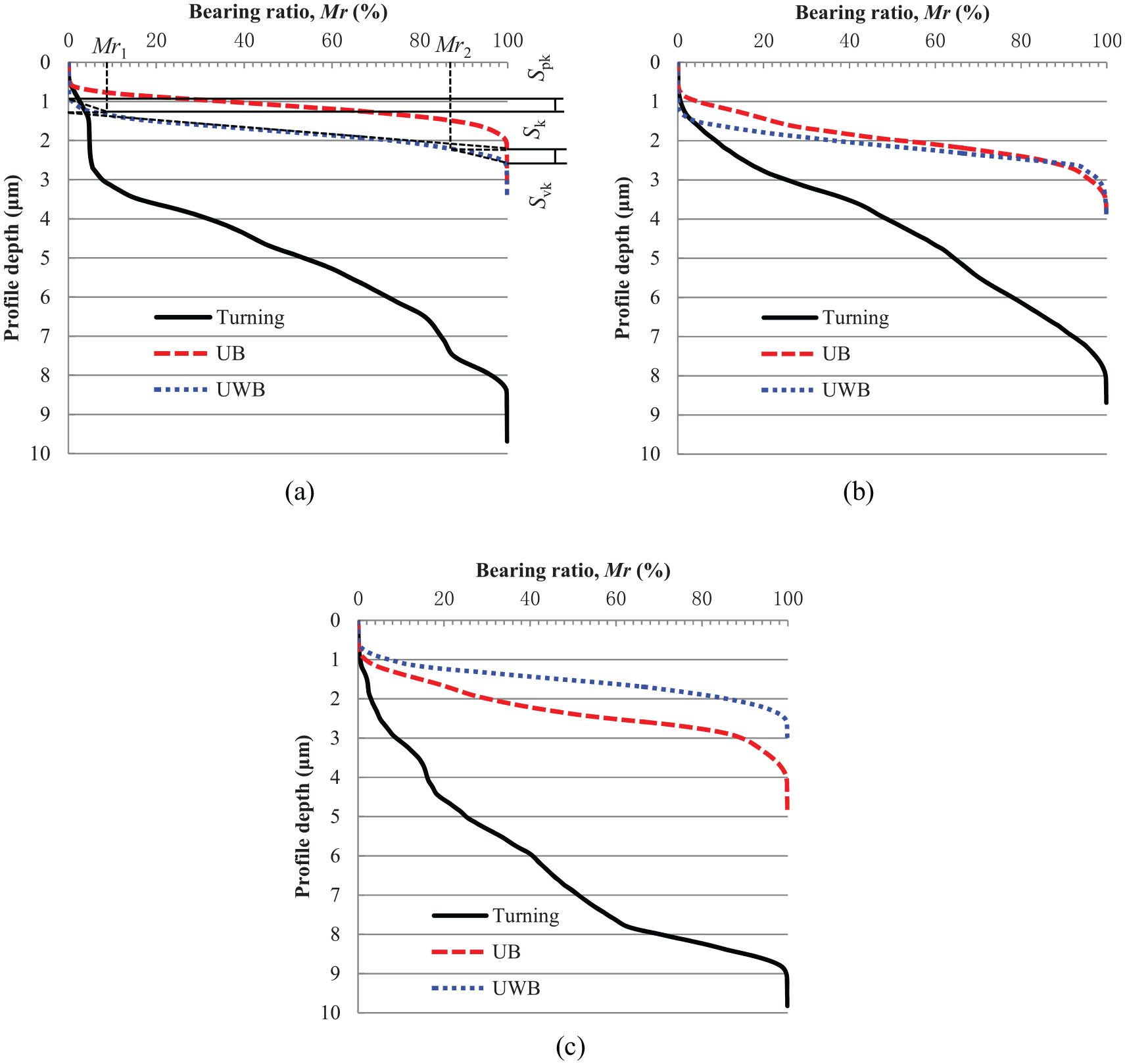
Bearing ratio curves evolution by subsequent burnishing following turning with feed: (a) f = 0.1 mm/r, (b) f = 0.2 mm/r, and (c) f = 0.3 mm/r.
Figure 7 also shows that the distribution of ordinate density becomes much more concentrated as a result of surface roughness improvement by subsequent burnishing when compared to that by turning process. That is, the bearing ratio curve of turning is located far below the curves of ultrasonic-assisted burnishing. Moreover, the inflection point of the bearing ratio curve is relocated in the degressive direction when the subsequent burnishing is transformed from room temperature to medium temperature in the case of surfaces obtained by turning with feed f = 0.1 and 0.2 mm/r, and it takes to be the opposite for surface obtained by turning with feed f = 0.3 mm/r. The reason can be also attributed to the surface damaged as a result of excessive folding.
The changes of functional parameters including Spk, Sk, and Svk are shown in Figure 8. The Spk parameter is the average height of the profile peaks above the roughness core profile, which determine the wear resistance of the surface on the running-in stage. A smaller Spk corresponds to a shorter running-in stage during the operation process. As can be seen from Figure 8, the turned surfaces have the largest Spk, then the surfaces obtained by UB, and the smallest are those obtained by UWB. That means, the running-in time for the burnished surfaces is greatly shortened than those obtained by turning. The main reason for this is that the burnishing treatment can flatten the roughness peaks of the turned surfaces. The Sk parameter is the core depth of the machined surface, which allows predicting the wear resistance at the long-term operation. During operation, there is a high mechanical resistance, and therefore, the manufacturing process is controlled by giving small Sk. Figure 8 also shows a great decrease of Sk by UB and UWB when compared to those obtained by turning process. As a result, it is beneficial to the workpiece used in extreme wear conditions to resist mechanical friction. The Svk is the average depth of the profile valleys below the roughness core profile, which is the sub-surface that retains oil or other solid lubricants during the operation process.40,41 Hence, a larger Svk corresponds to better lubricating property. It can be seen form Figure 8 that the lubrication properties of the surfaces obtained by UB and UWB will become worse because of the smaller Svk when compared to those of the turned surfaces. The reason for this can be attributed to the fact that the material at the peaks is squeezed to the valleys during the subsequent burnishing process, resulting in a reduction in Svk.
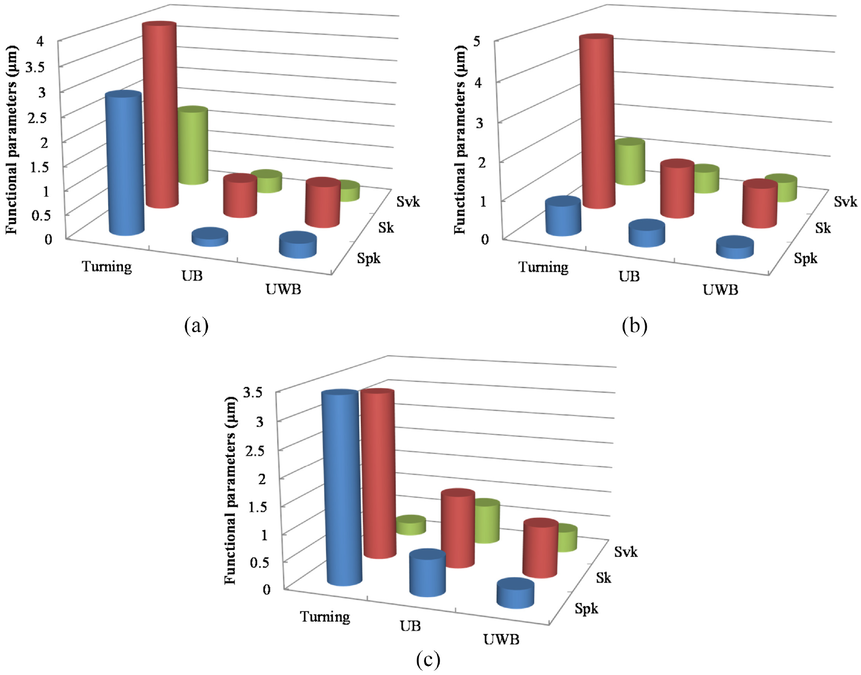
Functional parameters of Spk, Sk, Svk by subsequent burnishing following turning with feed: (a) f = 0.1 mm/r, (b) f = 0.2 mm/r, and (c) f = 0.3 mm/r.
Residual stress
Residual stress has a crucial influence on the fatigue performance of a machined part. The fatigue strength, in general, will increase in the presence of compressive residual stress, while decrease in the presence of tensile residual stress. Therefore, compressive residual stress is often generated by surface treatments in practical applications, thereby effectively improving the fatigue strength.
The causes of residual stresses on the machined surface include the plastic deformation caused by mechanical loads, plastic deformation caused by thermal loads, and the volume change caused by phase transformation. Under the action of mechanical load, plastic flow and extension occur on the machined surface, while the elastic recovery of bulk material will be restrained. As a result, compressive residual stress is prone to be formed on the machined surface. Under the action of thermal load, however, the machined surface will enter a fully plastic state on account of cutting temperature. The shrinkage of the machined surface when cooling will be restrained by the bulk material, which will result in the tensile residual stress on the machined surface. Furthermore, when the cutting temperature exceeds the phase transformation temperature and causes the change of metallographic structure on the machined surface, the nature of the residual stress should be determined based on the transformation of metallographic structures, which commonly occurs in the high-speed machining and grinding processes. In this study, the residual stress induced in both turning and ultrasonic-assisted burnishing are the results of the coupling of mechanical and thermal loads, in regardless of phase transformation. In the process of UWB, in particular, the temperature field will reduce the magnitude of compressive residual stress.
Common sense believes that the tensile residual stress generated by turning operation will be converted into compressive residual stress by burnishing. 42 As a matter of fact, the residual stress produced in a machining process is anisotropy. That is, the residual stress on the machined surface is different along the cutting speed and feed directions, respectively. The reason can be accounted to different plastic flow behavior and heat dissipation along the cutting speed and feed directions. Figure 9 shows the biaxial residual stress condition produced by turning and the subsequent burnishing. The results show that compressive residual stress is generated along cutting speed direction, while tensile residual stress is formed along feed direction during turning process. The reason can be attributed to the mechanical loads generated mainly by cutting force and thrust force components, which will promote the formation of compressive residual stress along the cutting speed direction. However, the contact state of the cutting tool and machined surface results in poor heat dissipation along the feed direction, and as a result, tensile residual stress is generated.
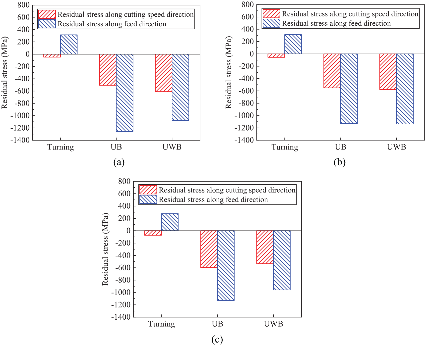
Biaxial residual stress evolution of laser cladded layer by the subsequent burnishing following turning with different feeds: (a) f = 0.1 mm/r, (b) f = 0.2 mm/r, and (c) f = 0.3 mm/r.
It is also obvious from Figure 9 that the tensile residual stress on the machined surface will shift to deep compressive state by subsequent burnishing. This is the result of severe plastic deformation of the machined surface during the subsequent burnishing. Furthermore, surface residue on the machined surface tends to flow along feed direction in burnishing. Thus, the value of the compressive residual stress along feed direction is enhanced and can reach −1.2 GPa, which is slight higher than that obtained by low plasticity burnishing (LPB) in our previous study. 31 It can be seen that the ultrasonic assistance can promote the formation of deep compressive residual stress in burnishing of laser cladded layer. However, the value of the compressive residual stress induced by UWB is decreased by 14% when compared to that obtained by UB. This is mainly due to the use of a temperature field, that is, thermal load in UWB treatment has a negative effect on generating deep compressive residual stress.
It is well established that the machining-induced residual stress play an important role in service behavior, particularly, in the presence of cyclic loadings. Indeed, the compressive residual stresses improve the fatigue strength, while the tensile stresses are prone to generate a negative influence on the fatigue life. 43 The formation of deep compressive residual stress by the subsequent burnishing may significantly improve the fatigue life in extreme conditions when compared to that by turning. If the fatigue cracks initiate from the stress concentration due to surface asperities, the large compressive residual stress may impede the crack propagation at the surface. 44
Evaluation of surface integrity
Surface integrity is a comprehensive characterization of the machined surface and subsurface properties. The surface integrity can fully reflect the wear resistance and fatigue resistance of the machined surface. The surface integrity can be quantitatively evaluated based on comprehensive evaluation method.
Radar diagram was utilized for the comprehensive evaluation on surface integrity in this present study. The data processing and drawing schedule is briefly described as following. 45 Firstly, all the data should be normalized by equation (4).
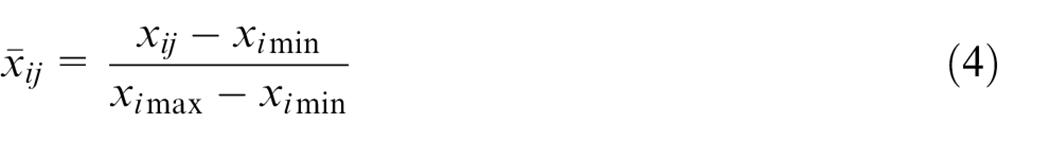
where xij, ximin, and ximax represent the jth, minimum, and maximum value of the ith index. As a result, the values of each index are converted to
Secondly, the data is standardized by equation (5) or (6) in the case of beneficial or non-beneficial index, where the beneficial index means that the larger of its value, the better the surface integrity is, while the non-beneficial index represents the opposite. In order to make each index value in the radar diagram generate the same effect on the surface integrity, the values of each index are further converted to yij, with which the larger, the better the surface integrity is.


Then, radar diagrams can be drawn based on the processed data. The area and perimeter of each radar diagram are utilized to quantitatively evaluate the surface integrity. However, the layout of the indexes when plotting radar diagram may not be the same, although it has been assumed that the contribution of each index to surface integrity is consistent. As a result, the area and perimeter of a radar diagram are not unique. In order to avoid the uncertainty of surface integrity evaluation, the average area ai and perimeter ci of radar diagrams with various layouts are calculated by equations (7) and (8), respectively.
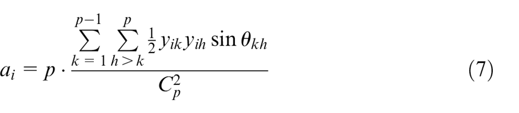
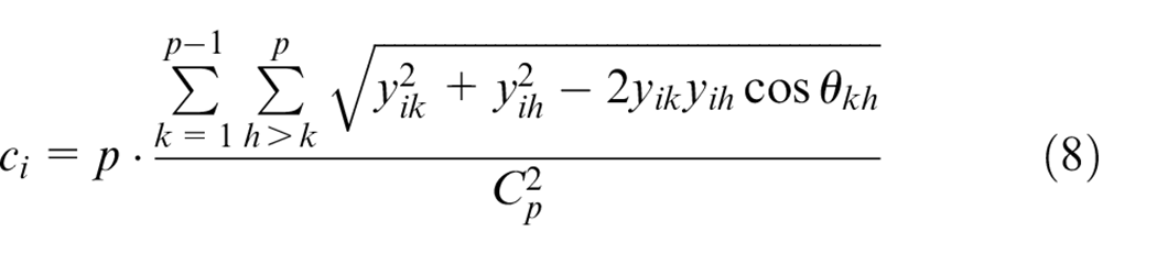
where p represents the number of the evaluation indexes, and θkh = 2π/p.
At last, the surface integrity can be evaluated based on equation (9).

where,
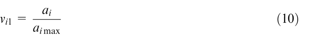
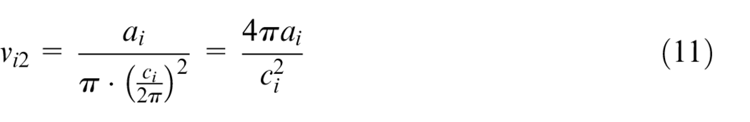
It should be noted that the vi1 reflects the relative size of the radar diagram, while the vi2 reflects the degree of balance between different indexes.
Among the factors affecting the surface integrity of the laser cladded layer, microhardness and reduced valley depth Svk are beneficial indexes (i.e. the larger values, the better surface integrity is), while the areal surface roughness Sa, reduced peak height Spk, and residual stress are non-beneficial indexes (i.e. the smaller values, the better surface integrity is). The radar diagrams obtained through the above approach are shown in Figure 10.
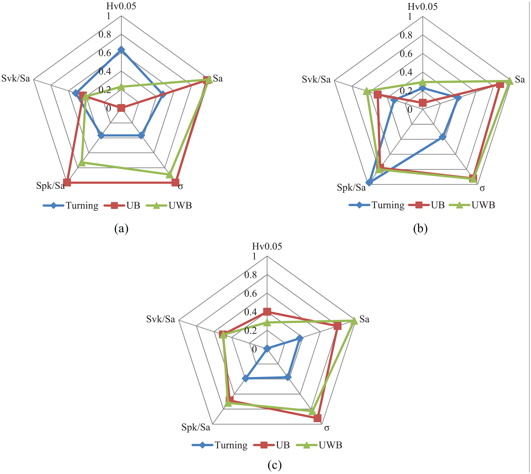
Evaluation of surface integrity by subsequent burnishing following turning with different feeds: (a) f = 0.1 mm/r, (b) f = 0.2 mm/r, and (c) f = 0.3 mm/r.
Figure 10 clearly illustrates that the surface integrity of the laser cladded layer can be significantly improved by subsequent burnishing when compared to turning. This is mainly reflected as the strong advantages of the burnishing treatments in terms of the deep compressive residual stress, low surface roughness, and the improvement of the microhardness. As a matter of fact, this is the result of severe plastic deformation of the machined surface under the rolling action of the burnishing ball. This is also the reason why the temperature field is utilized to improve the surface plasticity of the laser cladded layer, so as to enhance the effect of plastic deformation. In addition, the improvement of surface integrity by subsequent burnishing becomes more obvious as the feed used in turning increases. The reason can be attributed to the weakening of the surface integrity as the feed increases during turning process, that is, the deterioration of surface roughness, the increase of tensile residual stress and decrease of surface microhardness caused by high cutting temperature.
The comprehensive evaluation result on surface integrity of the laser cladded layer is shown in Figure 11. The results in Figure 11(a) show that the surface integrity is relatively poor by turning process and decreases with the feed increasing. Although the balance of various indexes of surface integrity in turning is good under the condition of small feed, as shown in Figure 11(b), the value of each indicator is mediocre, which leads to the poor surface integrity, as shown in Figure 11(c). The reason can be attributed to the increase in surface residue and thermal effects with increase of feed. In fortunate, the surface integrity of the laser cladded layer can be significantly improved by the subsequent burnishing. As shown in Figure 11(a), the quality of surface integrity reaches the minimum by UB treatment, while the maximum by UWB treatment following turning with the feed f = 0.2 mm/r. At the same time, the balance of various indexes for surface integrity is getting better and better with feed used in turning increasing, especially for the UB treatment, as shown in Figure 11(b). As a result, the compressive surface integrity is improved by 12.3%, 36.9%, and 334.4% by UB treatment, and 21.7%, 76.8%, and 315.7% by UWB treatment, respectively, when compared to those obtained by turning with feed increasing from f = 0.1 mm/r to f = 0.3 mm/r, as shown in Figure 11(c). The reason for the more than threefold increase of surface integrity after burnishing for a turned surface with feed f = 0.3 mm/r can be attributed to two aspects. On one hand, the surface integrity by turning is significantly reduced due to the deterioration of surface roughness as well as thermal softening on the machined surface with feed increasing. On the other hand, the surface integrity by burnishing is significantly improved due to the improvement of the hardness and the improvement of the balance of each index. It should be noted that the surface integrity reach the maximum value by UWB treatment following with turning at feed f = 0.2 mm/r. Therefore, the machining parameters can be regarded as the preferred parameter scheme for the high-efficiency and high-quality machining of the laser cladded layer. It can be also found from Figure 11(c) that the surface integrity can be improved by UWB rather than UB for turned surfaces with feed not exceeding 0.2 mm/r, while the change of surface integrity by UB and UWB is not much different for the turned surface with feed larger than 0.2 mm/r.
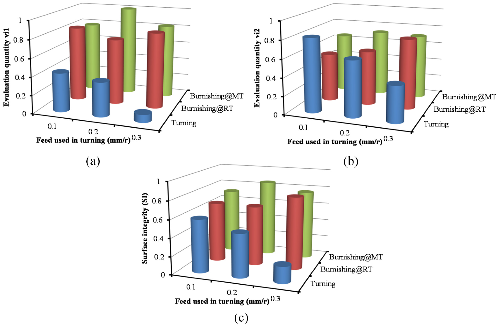
Evaluation results of the surface integrity by turning and subsequent burnishing: (a) evaluation quantity (vi1),(b) evaluation quantity (vi2), and (c) compressive surface integrity (SI).
On basis of this research, the ultrasonic-assisted burnishing process is preferred for improving the wear resistance of the laser cladded layer, especially under dry friction conditions. In addition, it also helps to improve the fatigue life of the remanufactured parts.
Conclusions
In this study, the combined effects of turning, ultrasonic-assisted burnishing at room and medium temperature on the surface integrity of laser cladded layers were comparatively analyzed. Key results and conclusions are as following.
Microhardness beneath the machined surface achieves the highest when turning with feed f = 0.1 mm/r as a result of repeatedly machining in the work-hardening zone. However, the microhardness is decreased by UB and UWB treatments because of the degeneration of the original strengthened microstructure. The changing of hardness is just the opposite when feed is increased in the turning process. This is due to the effect of thermal softening in hard turning, which is prone to decrease the microhardness, while severe plastic deformation in UB and UWB treatments, which will increase the microhardness on the machined surface.
The areal surface roughness Sa by turning is increased with feed increasing because of the increase of surface residue as well as feed marks. The areal surface roughness Sa is significantly reduced by 70% by UB when compared to that by turning because of the severe plastic deformation. In addition, the temperature field helps to improve the plasticity and, in turn, promote the severe plastic deformation in the UWB treatment, because of which, the surface roughness can be further decreased by 30% when compared to that by UB. In addition, the running-in stage of wear for the machined surface by ultrasonic-assisted burnishing is very short and quickly transforms into the prolonged stage of wear from the viewpoint of functional parameters, which is beneficial to parts used in extreme conditions.
The tensile residual stress on the machined surface will shift to deep compressive state by both UB and UWB treatments, which is beneficial for improving the fatigue life of the machined parts. However, the value of the compressive residual stress induced by UWB is decreased by 14% when compared to that by UB. It is because the thermal load generates a negative effect on generating deep compressive residual stress.
The surface integrity is improved by 12.3%, 36.9%, and 334.4% by UB treatment, and 21.7%, 76.8%, and 315.7% by UWB treatment when compared to those obtained by turning with feed increasing from f = 0.1 mm/r to f = 0.3 mm/r. Turning with feed f = 0.2 mm/r and UWB is preferred in machining the laser cladded layer based on the evaluation results of surface integrity.
Footnotes
Declaration of conflicting interests
The author(s) declared no potential conflicts of interest with respect to the research, authorship, and/or publication of this article.
Funding
The author(s) disclosed receipt of the following financial support for the research, authorship, and/or publication of this article: This work was financially supported by the National Natural Science Foundation of China (No. 52105455), and the College Student Innovation and Entrepreneurship Training Program in Shandong (No. S202010431072).