
Abstract
Nickel-based alloys are used in industrial sectors where high mechanical strength and corrosion resistance are required at high temperatures. However, these alloys have low machinability as a consequence of inherent properties. Some of these properties such as high cold work hardening rate and low heat conductivity may cause damages to the machined surface. Among the nickel-based alloys, one that has good properties for oil exploration is alloy 625. As the components made of this alloy are frequently used in very rough environments, this study sought to evaluate the influence of tool geometry, cutting conditions (feed and cutting speed) and tool condition (fresh or worn) on the surface integrity of turned alloy 625 parts in order to discover turning practices for this alloy that result in minimal damage to the workpiece surface. A secondary aim was to evaluate how these input variables affected the life of the coated carbide tools used in the turning experiments with this alloy. The main conclusions are that (a) the surfaces produced with a fresh tool with positive geometry had compressive residual stresses, while those produced with negative tool geometry had tensile residual stresses and (b) when a worn tool was used all the surfaces produced had compressive residual stresses.
Keywords
Introduction
One of the challenges facing the oil and gas industry is the development of materials that combine high corrosion resistance with mechanical properties suitable for use in oil wells. The great depth of these wells and the productivity required of them mean that such materials tend to be subjected to higher-than-normal stresses. One of the most promising solutions to this challenge is the use of nickel-based alloys, especially alloy 625. 1
Alloy 625 (UNS N06625) is a solid-solution–strengthened alloy composed mainly of chromium (∼22 wt%), molybdenum (∼9 wt%) and niobium (∼4 wt%) and a balance of nickel with small additions of titanium and aluminum. Its microstructure consists of an austenitic matrix (γ) with a small volumetric fraction of primary carbides (Nb,Ti) (C,N). The aluminum and titanium are added for de-oxidation purposes only and is not intended to precipitate the Ni3(Al,Ti) (γ′) phase. As the amount of niobium is relatively high, this alloy has a strong tendency to precipitate as Ni3Nb (δ) phase, which increases the alloy’s mechanical strength but reduces its toughness and corrosion resistance. Furthermore, even though the carbon content is very low, because of the high molybdenum and chromium content, M23C6 and M6C carbides tend to precipitate at the grain boundaries at the same temperature as Ni3Nb (δ), reducing the intergranular corrosion resistance of the alloy. For this reason, alloy 625 is generally used in the annealed (ASTM B446 Grade 1) or solution-annealed (ASTM B446 Grade 2) condition. 1
The low machinability of nickel-based alloys is related to their inherent properties. 2 The nickel-based austenitic matrix allows them to retain their mechanical properties even at high temperatures, making high energy levels necessary for chip formation and consequently requiring that large amounts of heat be generated. Moreover, the austenitic matrix makes the alloy very ductile so that chips tend to be long, increasing the chip–tool contact area and the tendency for a built-up edge to form. The high work hardening rate makes the burr (formed at the end of the depth of cut caused by plastic deformation of the chip) very hard, leading to notch wear and potentially increasing the hardness of the machined surface. The presence of hard carbide particles in the matrix promotes abrasive tool wear. Nickel-based alloys usually react with most commercially available tool materials, a factor that, together with the high temperature of the machining process, promotes diffusive tool wear. The low thermal conductivity of these alloys increases the amount of heat flowing through the tool, increasing the tool temperature and favoring several wear mechanisms.
Based on those characteristics, several recommendations should be followed when machining nickel-based alloys:
The tool material should have high hot hardness, abrasive wear resistance, good resistance to thermal shock and high chemical stability at high temperatures;
In order to minimize the hardening effect, the tool geometry must be positive with sharp edges, particularly in finishing operations, where feed and chip thickness are low; 3
The tool entry angle (χr) must be low enough to increase the length of contact between the cutting edge and the workpiece, and the tool point angle (εr) must be high in order to distribute the heat along a large portion of the tool edge and rake face and thus minimize wear; 4
The use of cutting fluid is fundamental in order to quickly remove heat from the cutting region quickly and so protect the tool against accelerated wear. 4
The surface integrity of a machined part is affected by changes in the metallurgical, chemical and topological properties of the surface produced by the machining process, such as surface roughness, variations in hardness, microstructural alterations and residual stresses. 5
The influence of cutting conditions on the microhardness of nickel-based machined parts is usually greater at the surface than the subsurface, where the effects of heat and deformation are neutralized by the volume of material and, among other factors, the low heat conductivity. When used in combination with higher cutting speeds, lower feeds, which generate higher specific cutting forces (Ks), produce greater surface deformation and therefore more cold work, that is, higher surface hardness. 6
The action of the tool nose against the workpiece during machining generates plastic deformation of the material, and the friction between tool and workpiece can generate thermal variations that can cause metallurgical transformations. 7 Both plastic deformation and variations in temperature can induce residual stresses in the workpiece surface and subsurface. Thiele and Melkote 8 show that cutting edge geometry has a major influence on the amount of residual stress generated. In general, either rounded or chamfered edges are most suitable for generating low residual stresses. Hua et al. 9 found that when machining materials with a high cold-hardening rate, the best cutting edge in terms of residual stresses is the one that has a chamfer beside a rounding radius. This kind of cutting edge generates compressive residual stresses, making it more suitable for applications where fatigue resistance and stress corrosion resistance are required.
According to Javidi et al., 10 increasing feed at low cutting speeds makes the surface residual stresses more compressive, but there is a lack of consensus among some authors about the influence of depth of cut (ap) and cutting speed (vc) on workpiece residual stress. According to Dahlman et al., 11 ap does not influence the final residual stress of the machined part. However, Delijaicov 12 points out that increasing depth of cut and feed together exerts a greater mechanical action (plastic deformation) than thermal action on the austenitic matrix of nickel-based alloys and also makes the surface residual stresses more compressive. According to Gunnberg et al., 13 an increase in cutting speed generates tensile residual stresses (which reduce fatigue strength) in the machined surface. Rech and Moisan, 14 in contrast, state that increased cutting speed causes the workpiece residual stresses to be compressive.
Sharman et al. 15 studied the influence of cutting fluid pressure on the surface integrity of workpieces obtained in turning operation. They used what they called “ultra-high-pressure coolant” with fluid pressure varying from 70 to 450 bars. They also injected the fluid in three different directions: toward the tool rake face, toward the tool flank face and on both directions. They concluded that the use of different directions of cutting fluid injection and different pressures of the fluid did not cause surface integrity to be significantly different from the surfaces obtained with conventional fluid application. However, when they used the highest fluid pressure (450 bars) applied toward the tool flank face, the lowest level of surface residual stress was obtained. The conventional application of the fluid induced a higher tensile stress in the near-surface layer and a larger compressive stress zone beneath this layer.
Axinte and Andrews 16 performed hole-making experiments (drilling followed by finishing operations of normal/special reaming or plunge milling) of a nickel-based superalloy (RR1000) manufactured via a powder route. The output variables of the experiments were tool life, hole accuracy, surface roughness, workpiece surface integrity and level of cutting torque. The main conclusions of this work were as follows: (a) drilling and normal reaming caused surface overheating with surface white layers and material dragging and (b) the special reamers with double relief angle of the cutting edge and the use of plunge milling for finishing of the hole generated holes within the required surface integrity standards. They also evaluated the relationship between the specific cutting energy per tooth per revolution and the depth of strained material and concluded that this relation can help the selection of the best finish machining operation.
Tool life is one of the most important economic issues in machining. Cutting conditions that reduce tool life are not economical because more tool replacements are required, increasing production costs. However, low cutting speeds and feeds result in low metal removal rates, making the production process less profitable. Significant efforts have been made in recent years to develop new tool materials that can meet the demanding requirements associated with the machining of nickel-based alloys. 17 Understanding tool wear and the kind of damage to which tools are subjected in order to find ways of increasing tool life is therefore very important. 18
Magri et al. 19 performed turning experiments in Inconel 625 alloys using conventional flood cooling and high-pressure cooling (70 bars) using three different directions of the fluid flow: toward tool rake face, toward tool flank face and with the fluid flow directed simultaneously to tool rake and tool flank faces (half of the flow rate in each of these faces). They concluded that the use of high-pressure cooling increased tool life because it impaired the development of notch wear. Workpiece surface roughness values were also improved by the use of high-pressure cooling. Another conclusion was that there was no difference in terms of tool life and surface roughness whether the high pressure fluid is injected toward either rake face or flank face, but the division of the fluid flow direction between flank and rake face harmed both, tool life and workpiece surface roughness.
This work seeks to establish a connection between these factors. It is essential to develop ways to cut alloy 625 parts to a high standard, that is, to increase tool life in order to ensure an economical cutting process while at the same time ensuring that the machined parts are undamaged by the machining process, as any damage to the surface of a part will adversely affect its performance.
The aim of this work was to evaluate the influence of tool geometry, cutting conditions (feed and cutting speed) and tool condition (fresh or worn) on the surface integrity of turned parts of alloy 625 in order to discover turning practices for this alloy that minimize damage to the workpiece surface. A secondary objective was to evaluate how these input variables influence the life of the coated carbide tools used in the turning experiments with alloy 625.
Materials and methods
The turning experiments were divided into two phases. In the first, fresh tools (without any wear) were used to machine the workpieces, whose surface properties were then measured. In the second phase, tool-life experiments were performed to find out what effect cutting conditions and tool geometry had on tool life and also to measure workpiece surface properties when worn tools were used.
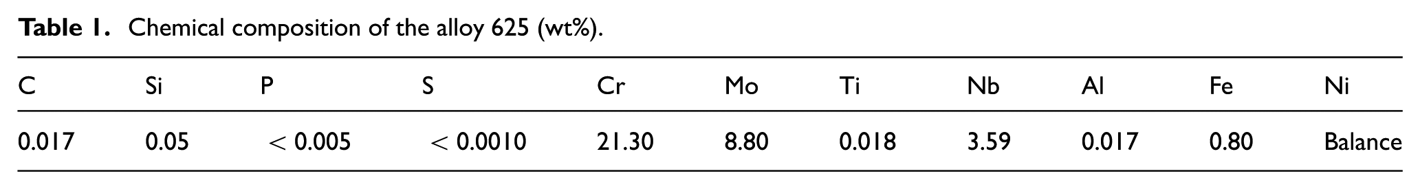
The chemical composition of the alloy 625 used for the workpiece in the experiments is shown in Table 1. The alloy was used in the hot rolled and annealed (at 960 °C during 4 h) condition, corresponding to ASTM B446 Grade 1. The mechanical properties of the alloy were determined experimentally and are shown in Table 2.
Chemical composition of the alloy 625 (wt%).
Mechanical properties of the alloy 625.
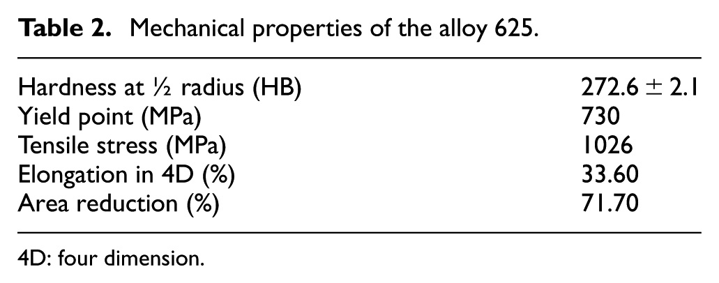
4D: four dimension.
The coated carbide inserts used in the experiments were ISO code CCMT 120404-MF 1125 (positive geometry) and CNMG 12 0404-SM 1125 (negative geometry). They were ISO S20 grade (S15–S25) and made of fine carbide grains with a physical vapor deposition (PVD) coating. The tool holders were ISO code PCLNR-2525M12 for the negative geometry and SCLCR-2525M12 for the positive geometry. 22 A water-miscible semi-synthetic cutting fluid was used in the experiments and was injected abundantly and at low pressure (conditions imposed by the machine tool pumping system). The CNC lathe had a 20-kW main motor and maximum spindle rotation of 4000 r/min with continuous variation of the spindle speed.
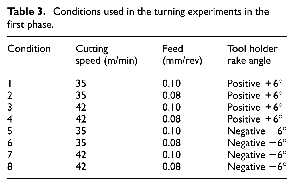
In the first phase of the experiments, the workpieces were turned using eight different conditions (Table 3) and a constant depth of cut (0.5 mm). These conditions are similar to those recommended by the tool supplier for finish turning of this alloy. 17 The cutting edges used in this phase were fresh; that is, they did not have any wear.
Conditions used in the turning experiments in the first phase.
The workpiece surface roughness was measured using a Mitutoyo portable roughness meter with a cut-off length of 0.8 mm and sample length of 4 mm (Ra and Rz roughness parameters were measured). The workpiece was not removed from the machine to the roughness measurement.
The residual stresses in the machined surface were evaluated using the blind-hole method as specified in the ASTM E837 standard. The analysis of the residual stresses was based on the first measurement obtained in each hole (surface value).
The Vickers microhardness of the machined surface and subsurface was measured with an indentation time of 10 s and load of 1 kgf. The distance between two successive measurements was at least 2.5 times the indentation diameter, as specified in the ASTM E384 standard. In each workpiece, 10 measurements were taken along the workpiece radius at 25-µm interval from the surface toward the core of the part. The measurements were offset diagonally from each other so that they were as close to the surface and to each other as possible, and at the same time, the minimum necessary distance between two neighboring measurements was maintained.
The surface and subsurface microstructures of the machined workpiece were prepared for metallography using a conventional procedure. The specimens were embedded in Bakelite, ground with sand paper and polished with a diamond suspension. The surfaces were then etched with Glyceregia (10 mL hydrochloric acid, 10 mL nitric acid and two drops of glycerine). The specimens were analyzed by optical microscopy.
In the second phase of the cylindrical turning experiments, tool-life experiments were performed. These were carried out using conditions 1, 4, 5 and 8 in Table 3 because these produced the highest and lowest values of compressive residual stress (conditions 1 and 4) and tensile stress (conditions 5 and 8) during the first phase. In the second phase, after each pass of the tool on the workpiece, surface roughness was measured and the tool (only the insert) was removed from the machine and placed under an optical microscope (with a digital camera with image processing software connected to it which allowed a 40× magnification of the tool worn region) in order to measure its flank wear. This procedure was repeated until the tool flank wear, VBmax, was 0.3 mm, which was considered to correspond to the end of the tool’s life.
The workpiece surfaces produced with worn tools (when flank wear was 0.3 mm) were assessed using the same surface and subsurface analysis carried out in the first phase of the experiments.
Results and discussion
First phase of the experiments
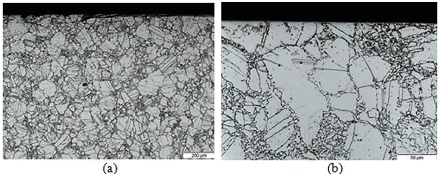
The core of the alloy 625 bar used in the experiments presented M6C-type carbides in an austenitic matrix as a result of the annealing heat treatment. The grain size measured according to the ASTM E112 standard is ASTM 13. Figure 1 shows the surface of the bar (before turning). There is a high degree of twinning and non-uniform distribution of grains.
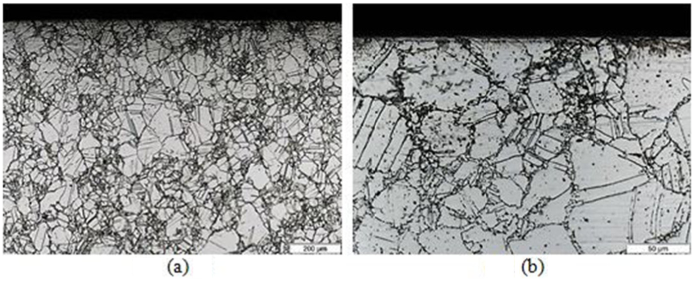
Micrographs of the region close to the surface of the bar before machining: (a) 100× and (b) 500×.
Figures 2 and 3 show micrographs of the machined surfaces of the alloy 625 turned using conditions 2 and 6. No microstructural alterations can be observed in the region close to the surface. Therefore, it can be concluded that the levels of deformation and heat imposed by the machining process were not high enough to cause changes in the material observable by optical microscopy. It is important to note that neither with these cutting conditions nor with any of the other conditions used were alterations observed.
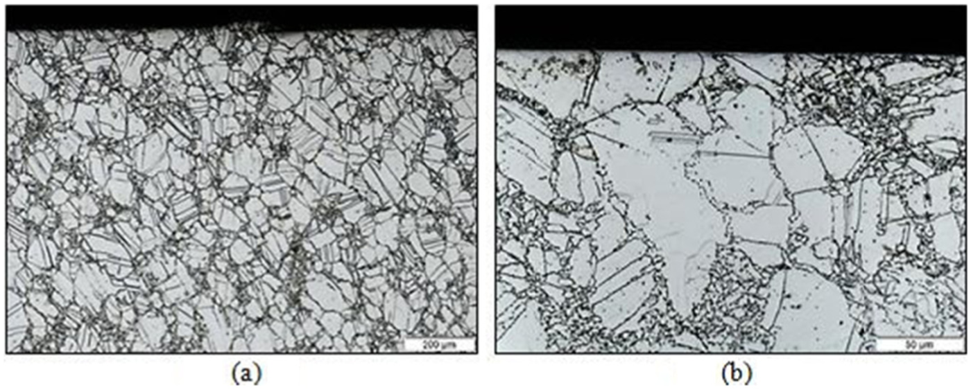
Micrographs of the machined surface for condition 2: (a) 100× and (b) 500×.
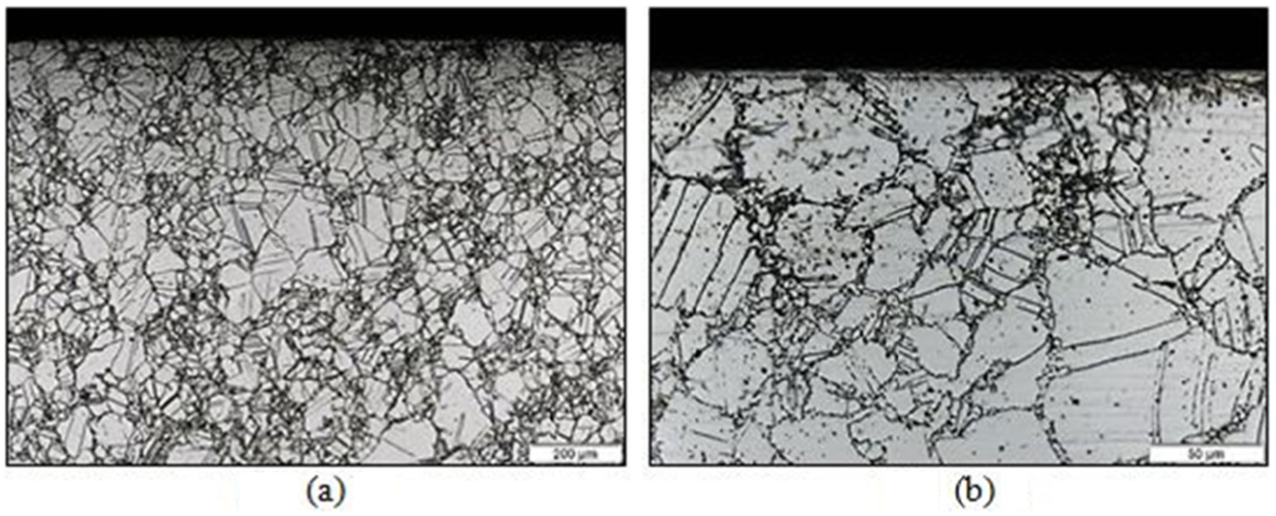
Micrographs of the machined surface for condition 5: (a) 100× and (b) 500×.
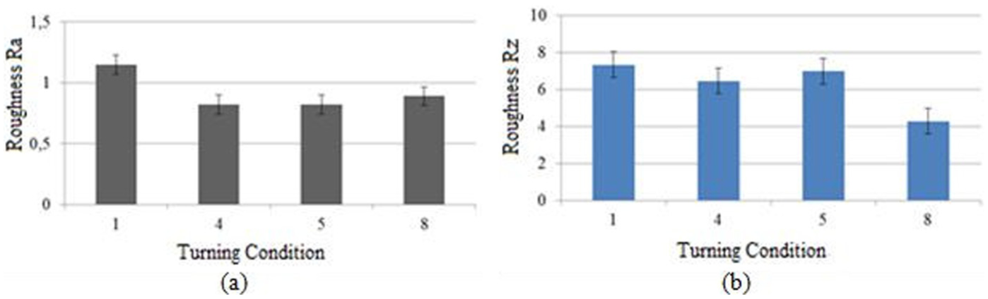
Figures 4 and 5 show the surface roughness values (Ra and Rz, respectively) measured during turning of the alloy 625 for the different conditions used. Each bar in the figure is an average of three measurements 120° apart of the roughness of the cylindrical surface of the workpiece.
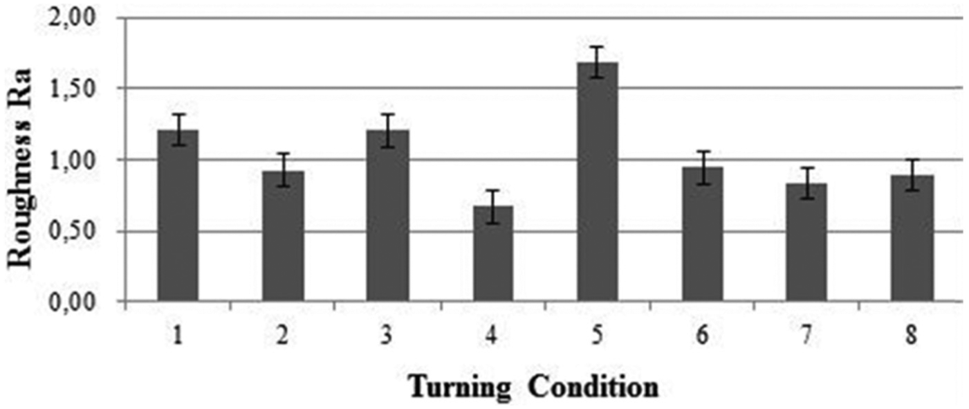
Ra roughness values for all the conditions used.
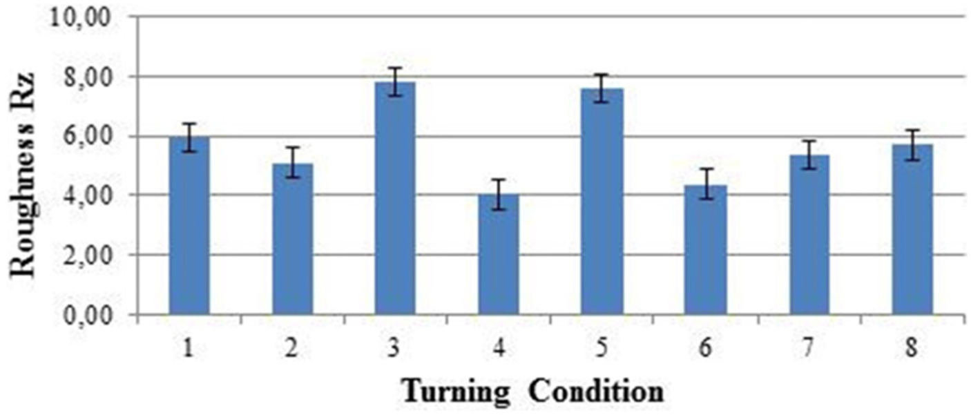
Rz roughness values for all the conditions used.
The highest values of Ra and Rz corresponded to conditions 1, 3 and 5, which had the highest feed. This result can be explained by the fact that this parameter has a geometrical influence on the roughness profile. 21 The other input parameters, such as tool geometry and cutting speed, did not have a strong influence on surface roughness. When tool geometry was changed from positive to negative, roughness increased in some cases but decreased in others. When cutting speed was increased, roughness generally decreased, but this influence was not the same in all cases. For example, comparison of condition 1 with condition 3 and condition 6 with condition 8 shows that the increase in cutting speed did not cause any variation in the Ra roughness value. These two parameters (cutting speed and tool geometry) do not contribute to the geometry of the roughness profile, and they would indirectly influence it if they had induced either tool vibration or deformation of the workpiece surface, what did not occur.
The higher the roughness of a surface, the worse will be the material behavior in terms of fatigue and corrosion because each roughness peak acts as a stress concentrator, accelerating fatigue and corrosion failure. 22 The parts machined using conditions 1, 3 and 5, all with a feed of 0.1 mm/rev, can therefore be expected to exhibit worse behavior when used in corrosive environments and with cyclical loads.
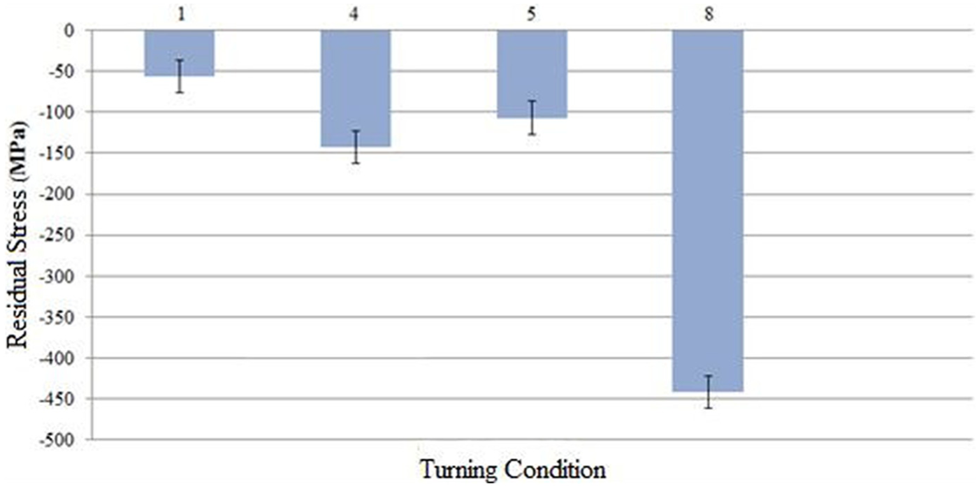
Figure 6 shows the results for the residual stress in the alloy 625 surfaces turned in the experiments in the first phase. The use of positive geometry is beneficial for the surface, as in all the experiments using this tool geometry the stresses in the surface were compressive. 23 When the tool geometry was negative, all the surface residual stresses were tensile, which adversely affects the part’s fatigue and stress corrosion resistance. 24 The reason for this result is that negative tool geometry generates a higher specific cutting force (Ks) in ductile materials such as alloy 625 because it causes a decrease in shear angle and an increase in chip deformation, which in turn increases the amount of heat generated in the primary shear zone. Moreover, when negative geometry is used, the chip spreads more on the tool rake face, increasing the friction between chip and tool and, in turn, the heat generated in the secondary shear zone. This heat is dissipated through the chip, workpiece and tool. However, the low heat conductivity of alloy 625 does not allow a lot of heat to be dissipated through the chip and workpiece. In other words, the heat going through the workpiece does not penetrate deep into the material because of the low heat conductivity of the workpiece and is instead confined to the surface region, causing this to expand thermally. However, the cutting fluid immediately removes the heat from the surface next to the recently formed chip, making it contract. In contrast, the subsurface, which does not receive so much heat, is not subjected to such an intense process of expansion and contraction and tries to restrict movement of the surface. As the last movement of the workpiece material just separated from the chip was a contraction because of the fast cooling caused by the cutting fluid, the subsurface tries to stretch the surface, which tries to contract, generating tensile residual stress in the surface. When the tool used has positive geometry, there is reduced chip deformation and heat generation, making the surface residual stress compressive.
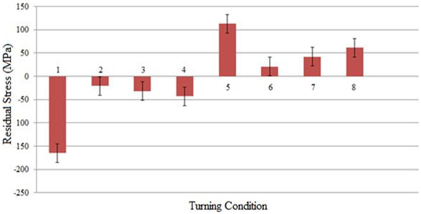
Residual stress in the alloy 625 surfaces turned in the experiments in the first phase using the blind-hole method as described in ASTM E837.
The magnitude of the residual stress, whether tensile or compressive, was higher when the workpiece was cut using a cutting speed of 35 m/min and feed of 0.10 mm/rev (Figure 6), the condition with the lowest cutting speed and highest feed of all the conditions used. As already cited, increasing the feed tends to increase compressive residual stresses in the surface. The results of this study show that tool geometry (tool rake angle) determines whether the residual stresses will be tensile or compressive and that the combination of feed and cutting speed defines the amplitude of the stress. Conditions 2 and 6 did not generate residual stresses in the surface, since the stress values were smaller than the margin of error with the blind-hole technique (around 20 MPa). These conditions correspond to the lowest cutting speed and feed. In other words, a low material removal rate results in low residual stress, as expected.
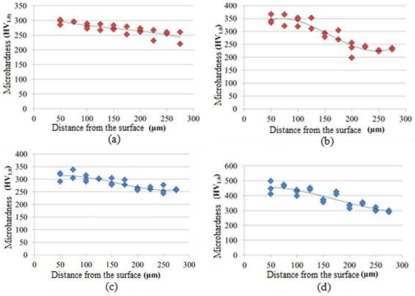
The microhardness of the workpiece measured between 50 µm from the surface (the minimum distance that can be used while ensuring that measurements are not compromised by the edge effect) and 275 µm from the surface (the distance at which the hardness is close to that of the alloy before machining) is shown in Figure 7. The results are shown for conditions 1, 4, 5 and 8. These conditions were used because they generated the highest residual stresses.
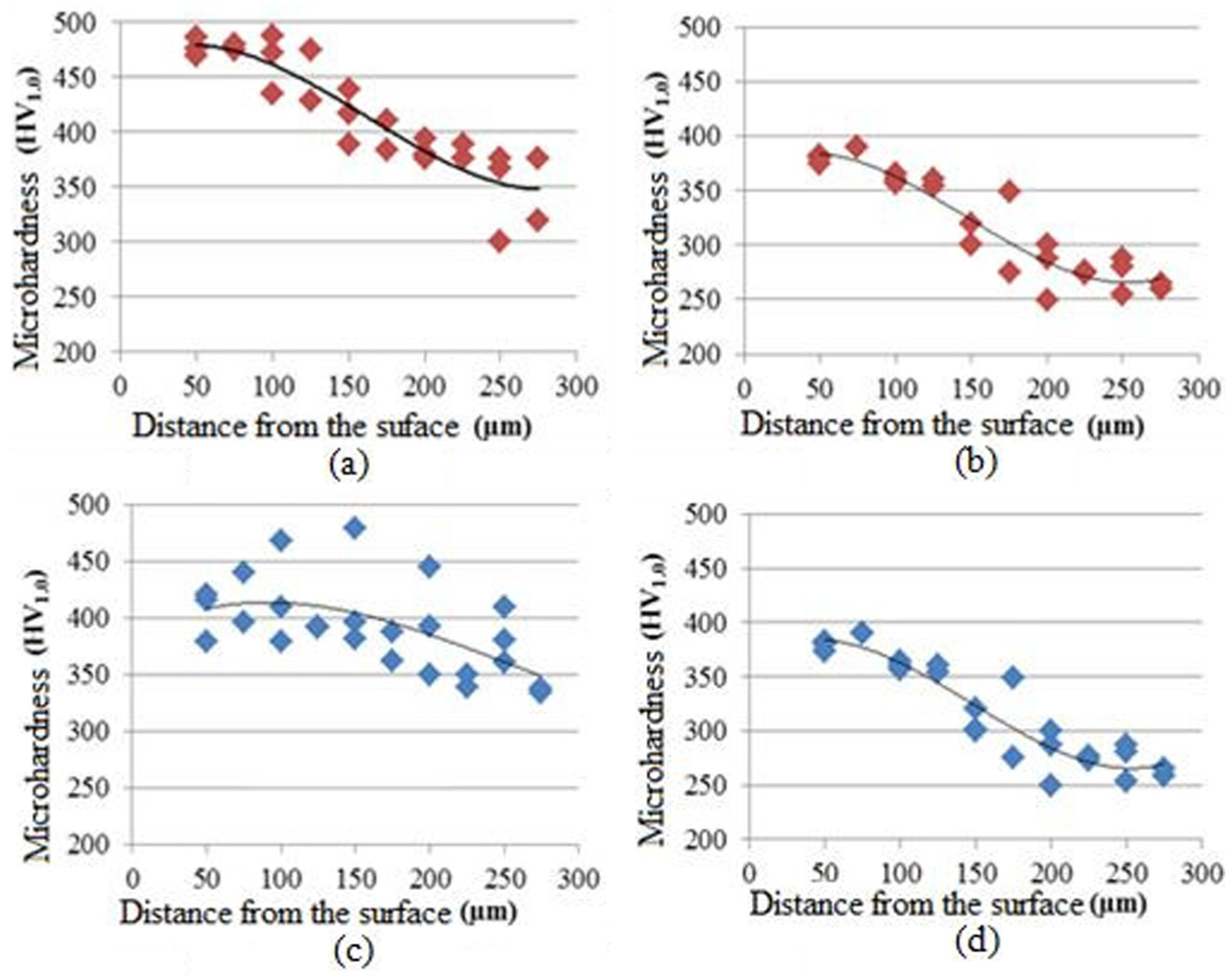
Vickers microhardness (1.0 kgf) against distance from the surface for conditions: (a) 1, (b) 4, (c) 5 and (d) 8.
The hardest surfaces were those produced using conditions 1 and 5 (Figure 7(a) and (c)). This can be explained by the fact that these conditions correspond to the highest feed and therefore produce the largest plastic deformation of the surface. The surface with the highest compressive stress was that which hardened the most (condition 1).
The higher specific cutting force (Ks) of the tool with negative geometry did not lead to greater hardening, as can be observed from comparison of the surface hardness for conditions 4 and 8, which used the same cutting conditions (f and vc) and different tool geometries. Therefore, the higher level of plastic deformation imposed by the negative geometry of the tool was not sufficient to generate different levels of hardness in the surface, as reflected in the similarity between the hardness curves for both conditions (Figure 7(b) and (d)).
For condition 5 (Figure 7(c)), which resulted in the highest tensile residual stress in the surface, the hardness of the subsurface (around 100 µm from the surface) was slightly higher than the hardness very close to the surface (50 µm). One possible explanation for this is that the subsurface limited the expansion of the surface (as already discussed) and was therefore plastically deformed, leading to the hardening seen in Figure 7(c).
Second phase of the experiments
As already mentioned, conditions 1, 4, 5 and 8 were used in the experiments in the second phase because these generated the highest levels of residual stresses.
Figure 8 shows the tool life (expressed as the volume of chips removed) for each condition tested. The material removal rates for all four conditions were very similar because the products of feed and cutting speed for all the conditions were also very similar (see Table 3). For conditions 5 and 8, where the tool geometry was negative, tool life was longer. These results are unusual as when machining very ductile materials with a high hardening rate, like alloy 625, there is a tendency for notch wear to develop faster when negative tool geometry is used because of the higher plastic deformation imposed on the chip and workpiece. 25 However, analysis of the tools used in the experiments under an optical microscope for all the conditions tested except condition 8 showed that notch wear was not the main type of wear contributing to reduced tool life (except for the experiments performed with condition 8). A possible explanation for the shorter tool life with positive geometry is the smaller cutting wedge of these tools, which makes them less able to support all the thermal and mechanical loads to which they are subjected during turning of the alloy 625.
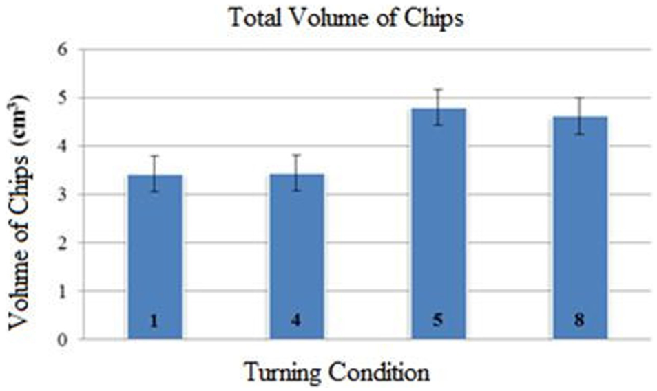
Volume of chips removed (which is directly related to tool life) for each condition tested.
Figure 9 shows micrographs of the surface machined with a worn tool (flank wear VBmax = 0.3 mm) using condition 8. This was the surface with the highest level of residual stress, as will be seen later. Once again, no microstructural alterations can be observed; that is, the amount of deformation and heat to which the workpiece surface was subjected during the process was insufficient to generate alterations in the surface that could be seen with the magnification used in these micrographs.
Micrographs of the surface machined using condition 8 (worn tool): (a) 100× and (b) 500×.
The surface roughness values (Ra and Rz) measured after turning alloy 625 with worn tools are shown in Figure 10.
(a) Ra and (b) Rz roughness measurements using worn tools for four different conditions.
The Ra values measured when worn tools were used were very similar to those observed with fresh tools (see Figure 4) except for condition 5, for which surface roughness decreased by half when a worn tool was used. This indicates that tool wear failed to produce a significant change in the tool nose shape, which is reproduced in the surface roughness profile of the workpiece surface, and that there were therefore no changes in surface roughness. However, when condition 5 was used, tool wear very likely removed all the tool coating, making the tool edge sharper and the Ra roughness lower.
The Rz values observed when worn tools were used were generally higher than those observed with fresh tools (Figure 5) with the exception of the values for condition 8. In other words, the condition of the tool had a significant influence on this roughness parameter. The fact that the condition of the tool did not influence Ra significantly but did influence Rz indicates that the kind of wear to which the tools were subjected did not affect the shape of the tool nose (and therefore did not influence Ra) but produced some scratches on the surface that had a strong influence on the peak-to-valley distance of the surface profile measured by the Rz parameter. However, Rz did not increase significantly for condition 8 because the end of tool life for this condition was caused by notch wear at the end of the depth of cut, and the wear height on the tool nose was small. Consequently, there was no damage to the tool nose that could scratch the machined surface.
Although Ra was unaffected by tool wear, the behavior of surfaces produced with worn tools in terms of mechanical fatigue and corrosion under stress will very probably be worse because stress concentration tends to be greater in surfaces with scratches, favoring both these phenomena. 19
Figure 11 shows the residual stress in the surfaces produced with worn tools in the second phase of experiments for the four conditions tested.
Residual stress for all conditions used (worn tools).
It can be seen that machining with a worn tool is beneficial for the surface in terms of residual stress regardless of the condition used. In general, the residual stress is low, and in condition 1, there is no residual stress in the surface when the margin of error for the technique used (blind hole) is taken into consideration. Analysis of the worn tools showed that they were always covered in workpiece material and that this had adhered to them, blunting the tools and increasing material deformation during the cut. Moreover, the low heat conductivity of alloy 625 made the material act as a thermal insulator, preventing heat penetrating deep into the workpiece surface. In other words, the deformation effect was greater than the thermal effect, making the residual stresses in all the surfaces machined with worn tools compressive. 26 The microhardness of the surfaces and subsurfaces machined with worn tools is shown in Figure 12.
Vickers microhardness of workpieces machined with worn tools: (a) condition 1, (b) condition 4, (c) condition 5 and (d) condition 8.
The graphs show that the surface of the workpiece was always harder than the core, indicating that the all the surfaces underwent cold work hardening. The greatest hardening occurred for condition 8 (Figure 12(d)), which also corresponded to the surface with the highest compressive stress (Figure 11). This result leads to the conclusion that the same mechanism that caused high compressive stress, that is, large deformation of the machined surface produced by a cutting edge covered in material that had adhered to it, also caused hardening of the workpiece surface. Since none of the conditions produced tensile stresses in the surface, the microhardness decreased continuously from the surface to the core of the material. None of the subsurfaces were harder than the surface, contrary to the results observed for condition 5 when a fresh tool was used (Figure 7(c)).
Conclusion
Based on the results of this study, it can be concluded that, when turning 625 nickel-based alloys under conditions similar to those used here:
The tool geometry determines whether the residual stress in the machined surface will be compressive or tensile. When fresh tools are used, positive tool geometry produces compressive residual stresses in the machined surface, and negative geometry, tensile stresses;
Hardening of the machined surfaces was greater in those surfaces with higher compressive stresses;
Greater tensile stress in the surface produces higher hardness in the subsurface;
The cutting conditions used were not severe enough to cause microstructural changes in the machined workpiece visible by optical microscopy;
The tools with negative geometry had longer tool lives than those with positive geometry;
The Ra roughness values of the machined surfaces produced with worn tools were very similar to those produced with fresh tools; however, the Rz values were generally higher when worn tools were used;
The residual stresses generated with worn tools were all compressive because of the deformation of the material caused by the tools, which were covered in workpiece/chip material;
The surface that hardened the most when worn tools were used also had the highest compressive stress.
Of all the conditions used in this study, condition 4 would appear to have caused the least damage to the machined surface since it had low surface roughness at the beginning and end of the tool life, compressive residual stress (which is beneficial for fatigue strength and corrosion resistance) and limited hardening of the surface due to the machining process. The only disadvantage associated with this condition is that, because it used positive tool geometry, the tool life was not as long as that achieved used negative geometry.
Footnotes
Acknowledgements
The authors are grateful to Villares Metals and Sandvik Coromant, respectively, for providing the workpiece materials and tools used in this study.
Declaration of conflicting interests
The author(s) declared no potential conflicts of interest with respect to the research, authorship and/or publication of this article.
Funding
The author(s) received no financial support for the research, authorship and/or publication of this article.