
Abstract
Ultrasonic burnishing is a relatively new method used for finishing workpieces to produce good surface quality. Ultrasonic burnishing does not involve material removal from the surface of the workpiece. However, the method has a significant deforming effect on the material, especially close to the surface, which is why it is vital to know the effect of the method to residual stresses in the material. This study looks at the residual stresses produced in two 34CrNiMo6-M tempering steel qualities of different hardness. The magnitude of stresses is examined using the hole drilling method. The hardness and surface quality of the finished workpiece are measured. The results show that the ultrasonic burnishing not only treats material on the surface efficiently but also deforms the material deeper, producing compressive residual stresses in the workpiece. The hardness increases after finishing and surface quality improves significantly. The roundness of the workpiece is improved and dimensional changes are minor.
Introduction
Ultrasonic processing is used for finishing metal surfaces in particular. The reviewed ultrasonic burnishing method is based on forging at an ultrasonic frequency. Ultrasonic burnishing is used for finishing after roughing and finishing with lathe. Ultrasonic finishing tool is installed in the tool holder of a lathe. The finishing head of the tool is set orthogonally to the workpiece and pressed with desired force. The surface layer of a workpiece plastically deforms under the combined effect of static force created by pressing the tool onto the workpiece and dynamic force created by ultrasonic oscillation system. Ultrasonic transducers convert high-frequency electrical power into ultrasonic mechanical vibration. The equipment forges the surface of the workpiece with a hard metal point more than 20,000 impacts per second. There is no removal of the material (unlike, for example, in grinding). It should be noted that the ultrasonic burnishing investigated in this article is different from more common ultrasonic finishing, a method that works on the surface of a workpiece by removing material with abrasive fluid. 1
The dimensional changes of the workpiece are minor in ultrasonic burnishing, and they can only be observed at a microlevel. The method could be used to work plane-shaped, curved and double-curved surfaces.1,2 In previous work, different ultrasonic burnishing parameters were tested. It was concluded that the range of parameters producing good surface quality is narrow. So far, testing is the only way to determine burnishing parameters for different materials. 3 Research by Hokkanen 4 states that initial values of surface roughness does not affect the finished surface quality significantly. More significant parameters are contact force, burnishing speed, feed and generator power. 4
Ultrasonic burnishing has been used in situations such as working on particularly hard and fragile materials that are not amenable to conventional finishing methods. 2 The method is of interest when considering finishing of injection molding dies. The ultrasonic finishing tool could be installed on machining center and used as finishing tool after machining the die. This provides more accuracy because the need for clamping of the workpiece is reduced. The ultrasonic burnishing of complicated geometries is also more cost-effective than conventional finishing. The industry has been cautious in applying the method; the ultrasonic burnishing is a new method, therefore, the surface integrity generated is previously unknown due to the lack of research. There are no previous journal papers or research on the subject except the studies by Huuki 3 and Hokkanen. 4
Surface integrity is a term combining different attributes of a surface, such as hardness, surface quality, structure and chemistry, affecting the mechanical and chemical behavior of a material, and thus influencing corrosion resistance and residual stresses. Residual stresses are stresses that remain in the material after any external forces loading it are removed. Usually, stresses are caused especially by casting and methods that have a powerful deforming effect on the material, such as machining and forming. Ultrasonic burnishing generates minor additional heat in the workpiece. The method does not remove material from the workpiece, but levels the profile peaks of the surface, at the same time producing potentially significant stresses close to the surface. These stresses may be unexpectedly high, especially if the piece is exposed to stress after machining. 5 In the study of ultrasonic burnishing, it is vital to establish the residual stresses caused by the ultrasonic burnishing in a workpiece and their magnitude and the directions in which the method produces them. The residual stresses, surface roughness and increase in hardness caused by ultrasonic burnishing are investigated in this study.
Experiments
Ultrasonic burnishing is applied to two workpieces of 34CrNiMo6-M tempering steel with hardness of 330 and 410 HV. The workpieces are 400 mm in length and premachined from 90 mm in diameter to 88 mm. Premachined surfaces are 340 mm from the free ends of workpieces. Ultrasonic burnishing is applied to surfaces that are 140 mm from the free ends of the workpieces. After ultrasonic burnishing, surface integrity of the workpieces is investigated by measuring surface roughness, residual stresses, hardness, out-of-roundness and diameter from the finished surfaces and from the unfinished surfaces for reference data.
Ultrasonic finishing system
The premachining is conducted by manual lathe; the lathe produces 11 kW of spindle power. Cutting parameters are the same for both workpieces. The feed is 0.2 mm/rev, the spindle speed is 300 r/min and depth of cut is 1 mm. The wolfram-carbide tool bit in use is SANDVIK DNMG 150608-MM 2025 with 0.8 mm nose radius. The HIQUSA ultra burnishing equipment (Figure 1) is used in this study. The cooling fluid used is mineral oil–water mixture of 5% concentration. Water-based cutting fluid with 10% concentration of Al2O3 abrasives was tested, but it was proven disadvantageous because the abrasives fused with the surface of the workpiece. The main purpose of the fluid is to cool the workpiece and tool and to wash away the removed particles. Cooling is important because excess heat increases tool wear rate. The cutting fluid is filtered through two filters, coarser prefilter and fine filter (www.hiqusa.com).
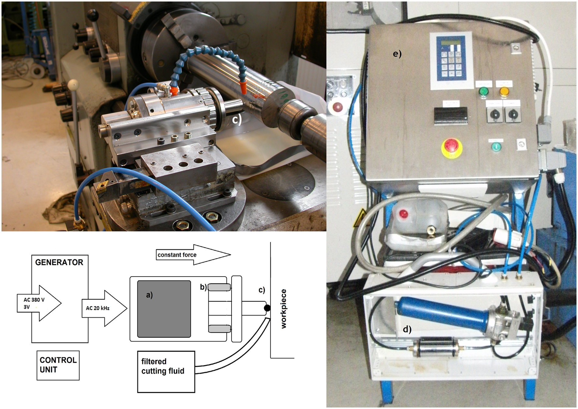
Ultra burnishing equipment for lathe (top). Schematic of burnishing equipment: (a) magnetostrictive converter, (b) spring to ensure constant contact and (c) tungsten tool head (bottom). Control unit and generator: (d) filtering system and (e) control unit and generator (right).
Ultrasonic burnishing parameters are 0.05 mm/rev for the feed and 80 r/min for the spindle speed, and the impact frequency is 20 kHz. The finishing head is wolfram-carbide ball 3 mm in diameter. The head is attached to a spring system that produces constant contact force. When the spring is set to specific compression, for example, to 1 mm, the spring produces contact force, which is measured. A contact force equal to 1 mm deflection is about 180 N, 3 mm deflection is about 200 N and 5 mm deflection is about 230 N. The compression setting for workpieces of 410 and 330 HV is 2.5 and 1.5 mm, respectively. The corresponding forces are 195 and 185 N. The depth setting is done to achieve desired contact force. The force varies little for different work materials due to elastic properties of materials.
Residual stress measurement system
The residual stresses are measured by the hole drilling method using two different measurement systems: SINT technology srl MTS3000 automatic residual stress measurement system and Stresstech Oy Prism residual stress measurement system based on hole drilling and electronic speckle pattern interferometry (ESPI) (www.sintechnology.com, www.stresstechgroup.com). Hole drilling method is a material removing method, where by drilling a hole of 1–4 mm in diameter, a local strain is achieved. Using traditional method such as SINT MTS3000, the hole is drilled in the center of a strain gauge rosette, by which the strain is measured. 6 ESPI method uses optical measurement to calculate the strains from interference pattern projected onto the surface of the workpiece, the green light pattern in Figure 2. Mathematical formulations such as integral method, power series or Kockelmann method are used to calculate stresses from the measured strains. Figure 3 illustrates the measuring setup for SINT: the workpiece is clamped on steel base, the drilling equipment is supported by three brass legs, the drill includes optical aligning lens and the strain gauge is glued on the workpiece.
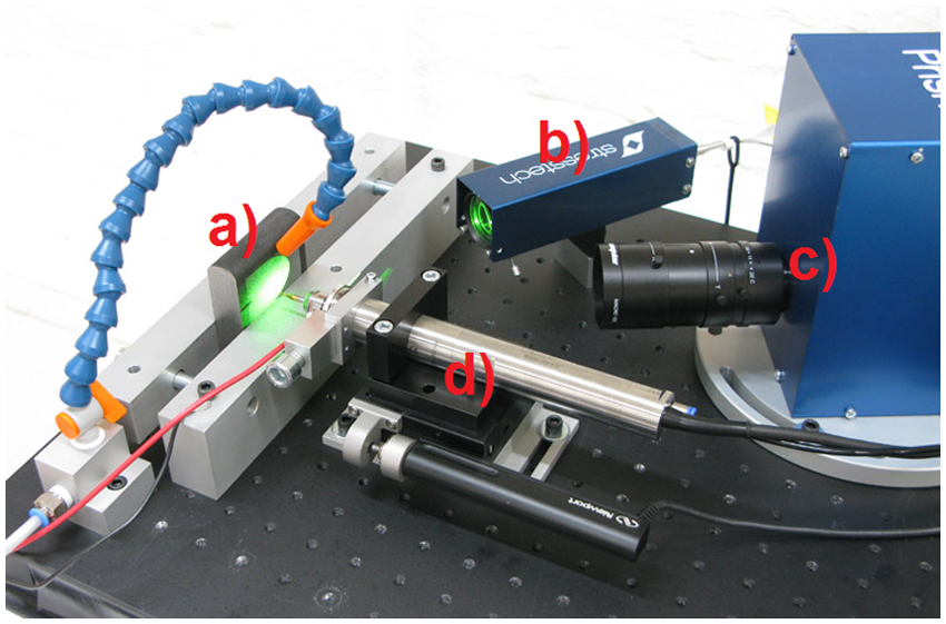
Principle of Prism measuring setup: (a) workpiece, (b) interference pattern projector, (c) measuring lens and (d) drill spindle (www.stresstechgroup.com).
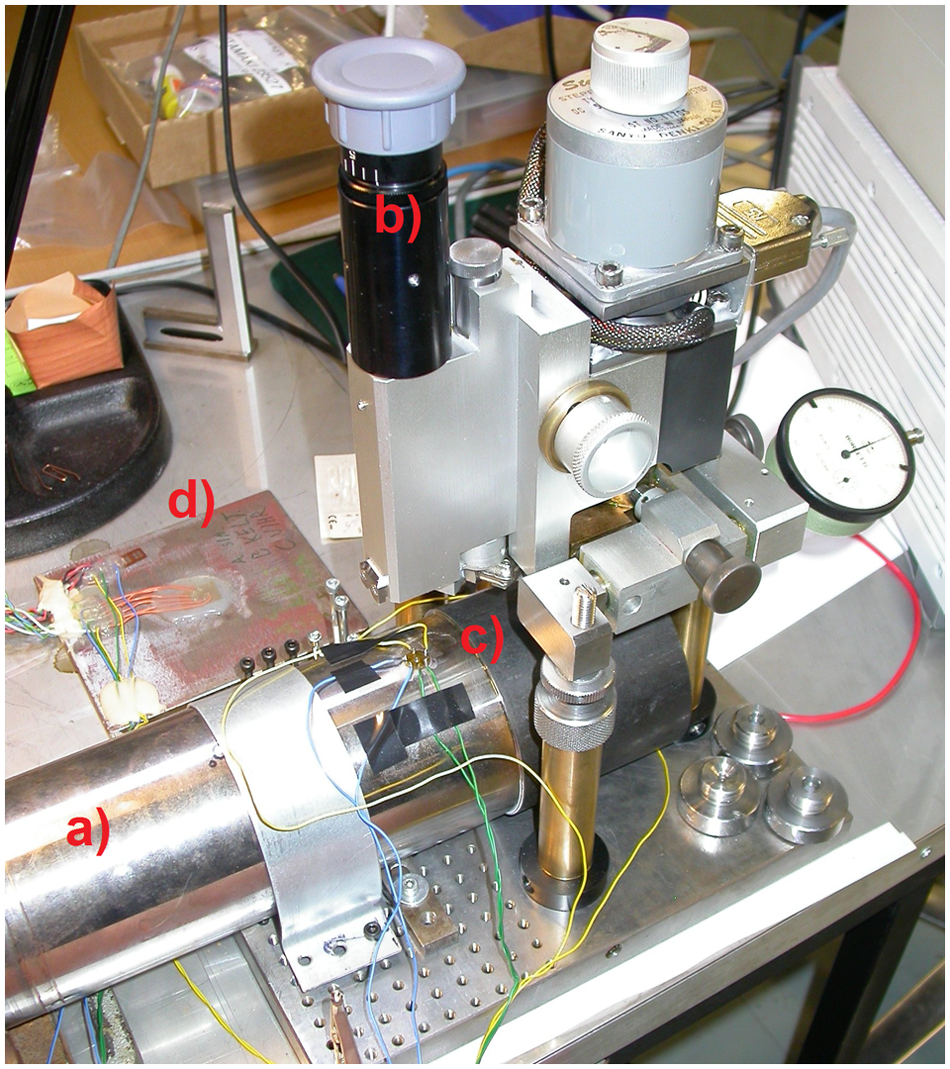
Residual stress measuring setup: (a) workpiece, (b) aligning lens, (c) strain gauge and (d) Wheatstone bridge.
Hardness measuring
The hardness is measured in three different points in both finished and unfinished surfaces by Vickers method with Brickers 220 hardness measuring device. The workpieces are cylinders in shape, so the shape causes error in the hardness value. The standard SFS-EN ISO 6507-1 provides equations for compensating the loss of accuracy caused by dimensional errors, but the total error for cylinder diameter used (88 mm) is insignificant, about 0.26%.
Surface roughness measuring
The surface roughness is measured by Perthen perthometer M4P measuring device. The device uses a touch probe to measure the topology of a line on surface. The measurements are in Ra values, which refer to the standard deviation of surface profile in micrometer.
Coordinate measuring
The diameter of workpieces is measured by numerically controlled coordinate measuring machine Johansson Ruby 4-4-4. The measuring head used is Renishaw ballpoint head. The machine resolution is 0.1 µm and has a measurement accuracy of 3.9 L 4 µm. The variable L is the distance measured in meters. The measuring range size is 400 × 400 × 400 mm3. The measurement program was JoWin.
Roundness measuring
The roundness measuring machine used is Talyrond 31. The workspace has a diameter of 125 mm and allowed workpiece size is 370 × 225 mm2 in diameter and 12 kg in weight. The device resolution is 0.01 µm. The measuring sensor is Talyminin linear variable differential transformer (LVDT), in which the measuring head is 2 mm in diameter sapphire ball. The radial resolution of spindle is 0.025 µm.
Results
This section presents the results of residual stress measurements, hardness testing, surface roughness measurements, diameter measurements and out-of-roundness measurements.
Residual stresses
The results of residual stress measurements are presented in Figures 4 and 5. The uniform stresses are calculated from measured strains by the power series method, which gives the best approximation of the true stresses (p. 19). 7 Figure 4 presents the residual stresses of the 410-HV workpiece. The solid line expresses the maximum compressive stress of the unfinished machined surface, which is used as the reference surface. The distribution starts with 300 MPa of compression and after 0.3-mm stress levels on to 500 MPa of compression. The dotted line presents the maximum stress in the finished surface, starting with 800 MPa of compression declining to 500 MPa. The broken line presents the minimum stress on reference surface starting from 100 MPa and increasing to 300 MPa of compression. The broken dotted line presents the minimum compressive stress of the finished surface, increasing from 450 to 600 MPa in 0.1–0.25 mm and then declining to 300 MPa. In summary, the maximum compressive stress increases in ultrasonic burnishing by 600–900 MPa, and the minimum compressive stress increases by 300–600 MPa.
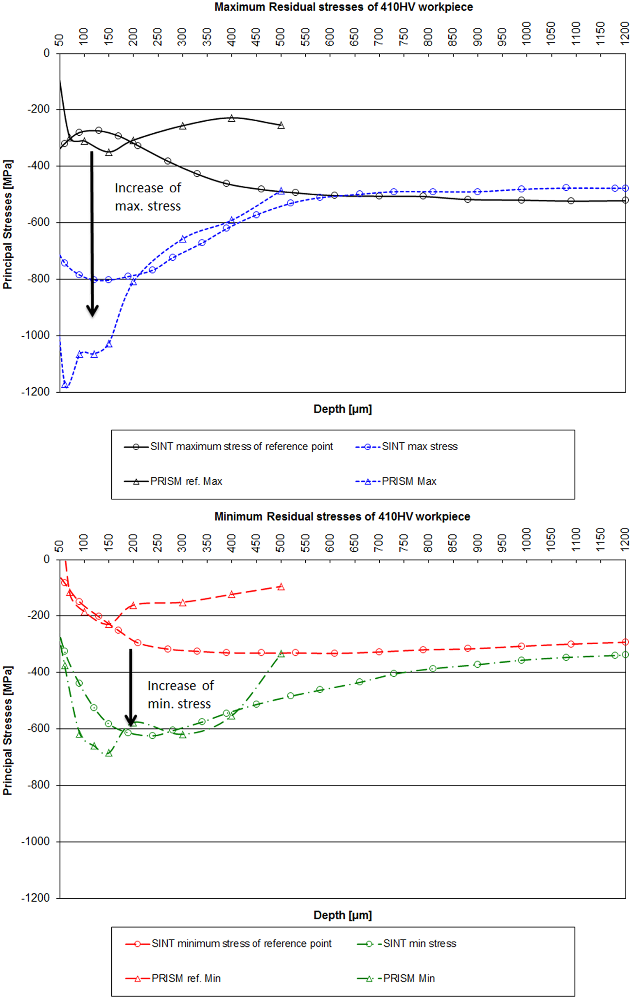
Residual stresses of 410-HV workpiece.
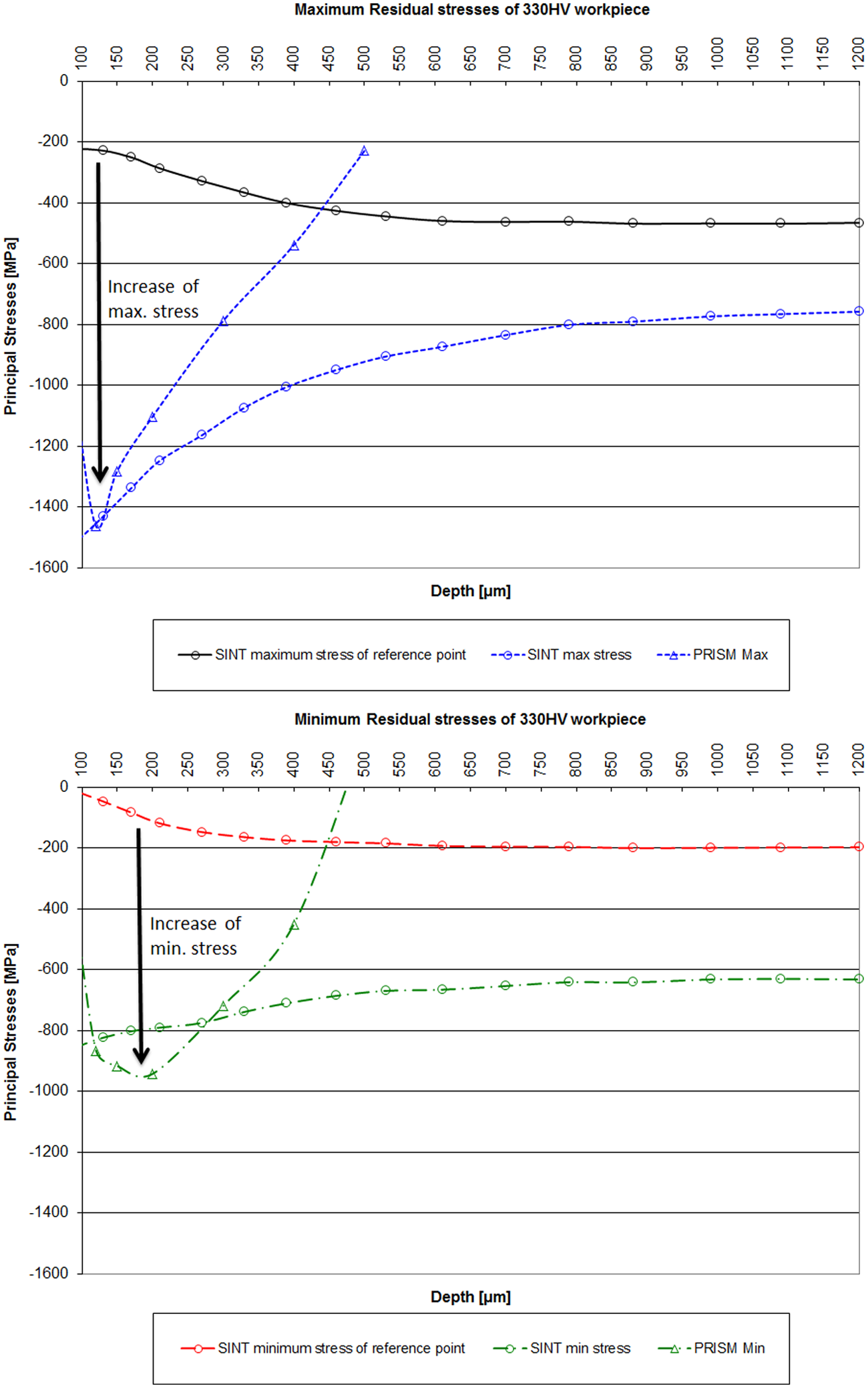
Residual stresses of 330-HV workpiece.
Figure 5 presents the compressive stresses of the 330-HV workpiece. Similar to Figure 4, the solid line presents the maximum reference stress, the broken line presents the minimum reference stress, the dotted line presents the maximum stress of the finished surface and the broken dotted line presents the minimum stress of the finished surface. The maximum stress increases in finishing by 1200–1400 MPa and the minimum stress increases by 800–900 MPa. The compression of 330-HV workpiece seems to go deeper than with 410-HV workpiece. The most probable reason for this is measurement error, the measurements with Prism equipment indicate that the stress state decreases faster than measured with SINT equipment.
Measurements with Prism and SINT are reasonably uniform. The greatest difference is with the depth of the stress state so that the measurements with Prism indicate that compressive stress decreases in lower depths than measured with SINT. The difference could originate from the long time period between measurements; measurements with SINT were done half a year earlier than Prism measurements. Creep causes the stresses to be released with time. Also the shipping could have exposed the workpieces to vibrations and temperature variations that affect stress state. Nevertheless, both measurements indicate extreme increase of stresses especially at the surface layer. There is no explicit error estimate for the residual stress measurements.
Hardness
Table 1 presents the hardness measurements of 330-HV workpiece. Hardness of ∼345 HV is measured in the premachined zone and ∼347 HV in the finished surface. The finishing-induced increase in hardness is negligible, and machining caused about 5% increase to the untouched surface hardness.
Hardness measurements of 330-HV workpiece.
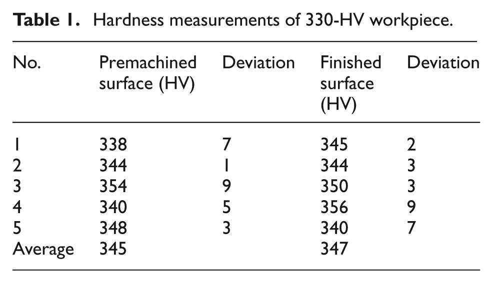
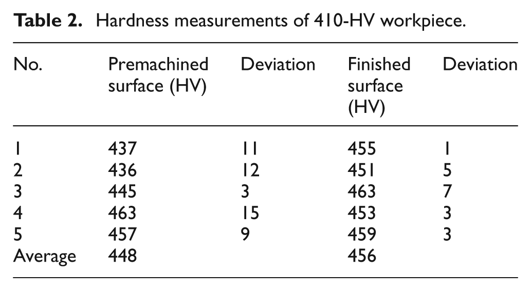
Table 2 presents the hardness measurements of 410-HV workpiece. Hardness increases from ∼448 to ∼456 HV in finishing, an increase less than 2%. The machining and burnishing increased hardness by 10% compared to untouched surface.
Hardness measurements of 410-HV workpiece.
Surface roughness
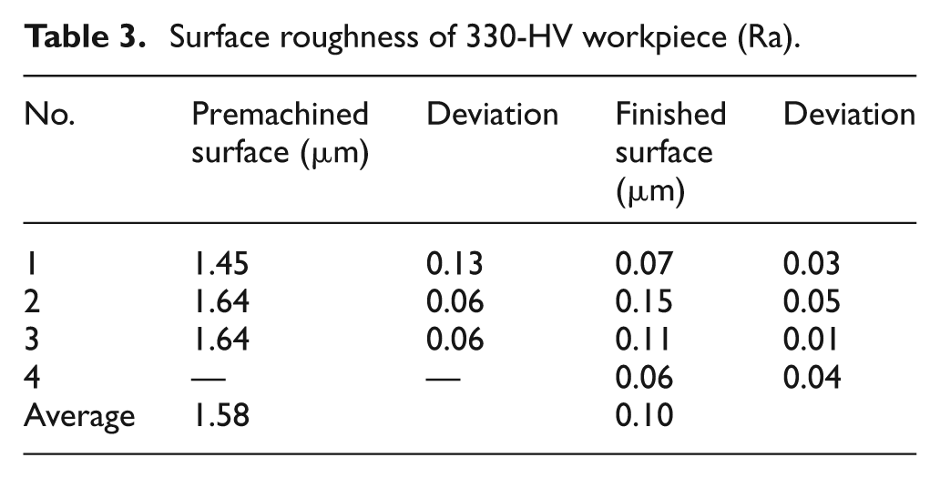
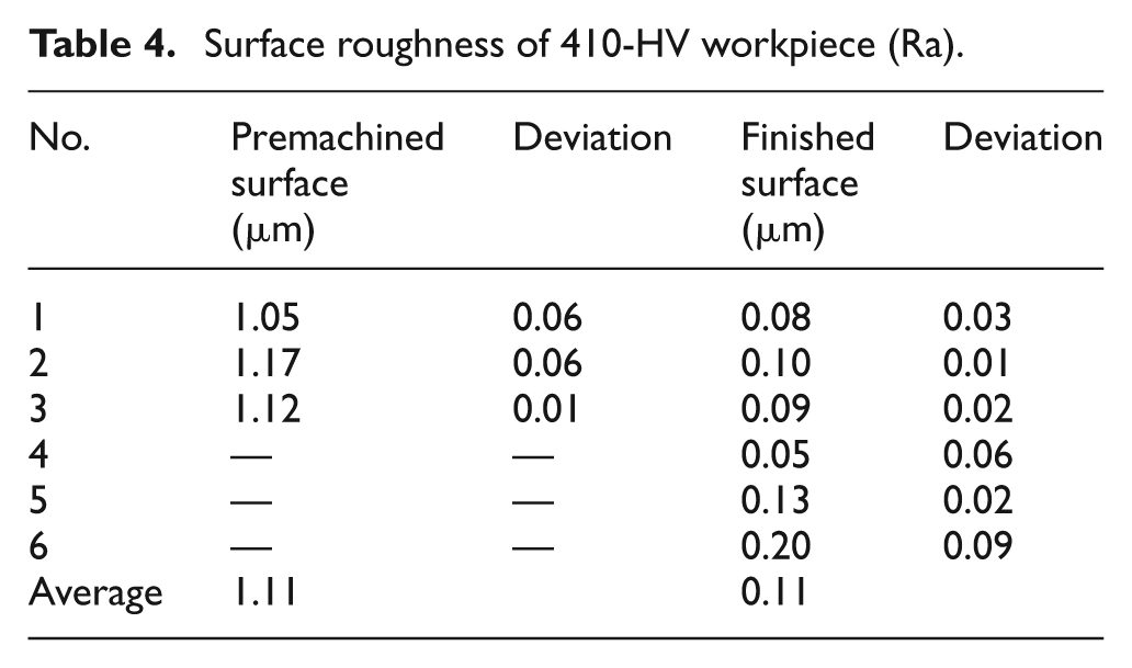
The surface roughness measurements of 330-HV workpiece are presented in Table 3. The average surface roughness in premachined zone is measured to be 1.58 µm, and in the finished surface, it is 0.10 µm. The surface roughness Ra value reduces in ultrasonic finishing by 1.48 µm on average. Table 4 presents the surface roughness of 410-HV workpiece. The average roughness in premachined zone is 1.11 µm, and in finished zone, it is 0.11 µm. The average reduction of Ra value is 1.00 µm.
Surface roughness of 330-HV workpiece (Ra).
Surface roughness of 410-HV workpiece (Ra).
Diameter
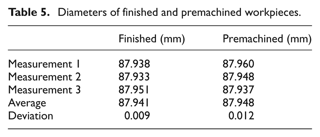
Diameters of workpieces before and after finishing are presented in Table 5. The average diameter after premachining is 87.948 and after finishing is 87.941. The average change in diameter is 70 µm.
Diameters of finished and premachined workpieces.
Roundness
Workpiece roundness is measured from premachined and finished surfaces. Figure 6 shows that the out-of-roundness is better with finished surfaces than premachined surfaces. The value of interest is peak to valley (PV), which indicates the difference between the highest and lowest values of the radius. The value can be seen in Figure 6 indicated by a flattened circle ◯. The uppermost image shows that the PV decreases with finishing from 11.55 to 6.5 µm, the second image shows similar decrease from 9.35 to 5.75 µm, and the last image shows decrease from 12.1 to 8.25 µm.
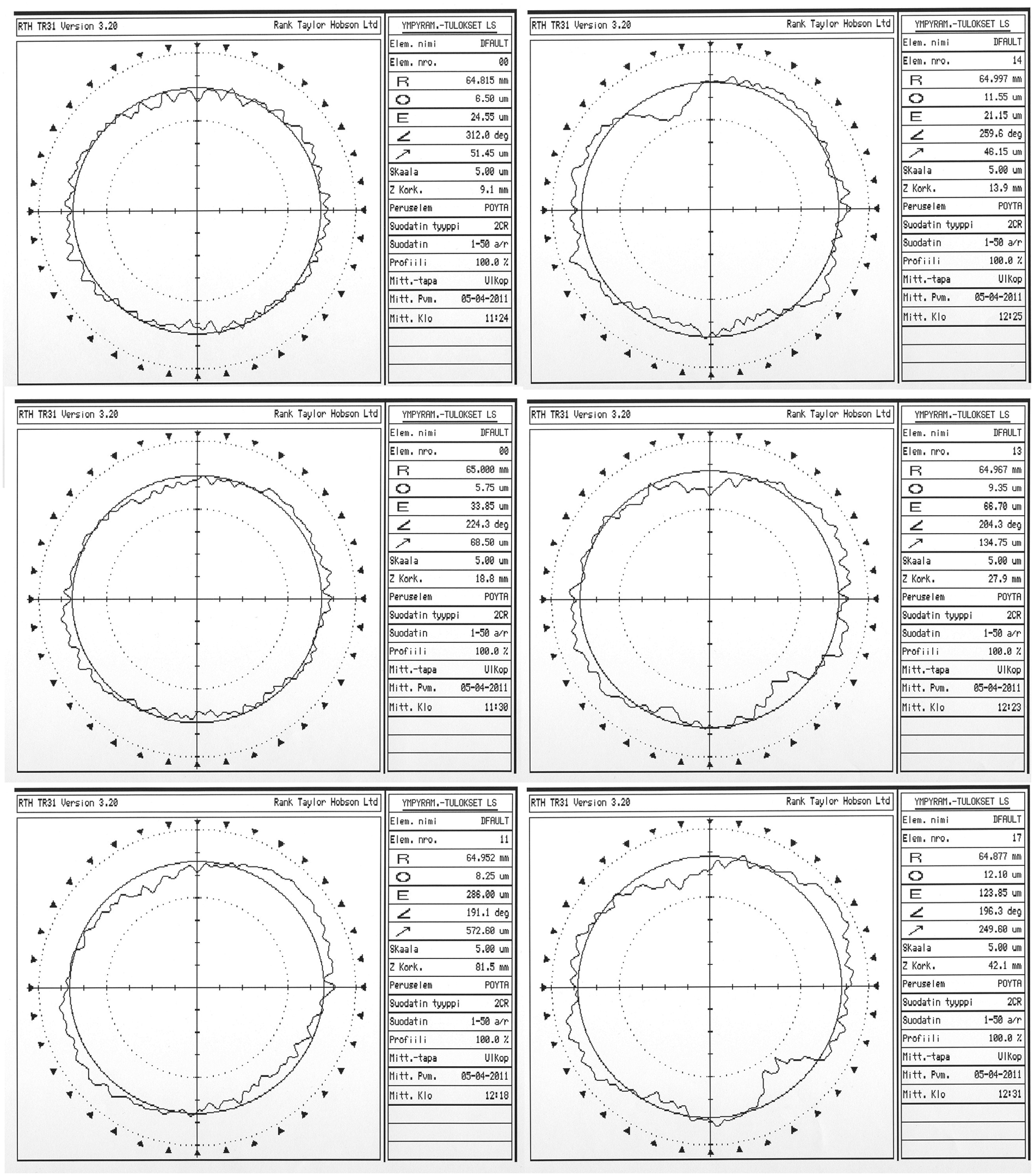
Workpiece roundness charts: (left) the finished parts and (right) the premachined parts.
Discussion and future work
The results of ultrasonic burnishing can be partly compared to regular burnishing with a cylindrical tool. Korzynski et al. 7 obtained surface roughnesses of 0.05–0.18 µm (ground 0.638 µm). They found (for 42CrMo4 alloy steel) microhardness to increase by 29% and fatigue strength to improve by 18% of the absolute value. 7 Comparing these results, and the data given in this article, the processes have similar effect on workpiece and improve surface quality and fatigue strength. Korzynski et al. 7 obtained the highest absolute compressive stress value of 461 MPa for a workpiece burnished with 250 N. In this article, experiments show that the highest compressive value was 900 MPa for a workpiece burnished with 195 N and 1400 MPa for 185 N. Therefore, it is reasonable to assume that the vibrations of the tool at ultrasonic frequency have a major role on mechanics of surface formation.
How the method affects different materials is still unknown, but the general idea is that surface roughness is improved in metallic materials, hardness is expected to increase and residual stress state is expected to be compressive if material is strain hardening.
More research should be done to predict surface integrity for different materials after ultrasonic burnishing and for finishing double-curved surfaces. Analytical or numerical methods may provide sufficient data to make accurate prediction. The microstructural changes of the workpiece should also be inspected. The mechanical process of work hardening and residual stress formation in ultrasonic burnishing is not known and should be researched to establish theoretical background for further use of the method. The research on finishing double-curved surfaces is needed to provide instructions on finishing parameters and optimal machining trajectories. For finishing double-curved surfaces, a machining center with more than three simultaneously running axes with force control is needed. Dimensional changes in geometrically nonuniform workpiece may occur due to high stresses.
Conclusions
The following conclusions are made based on experiments presented in this article. Ultrasonic burnishing affects the stress state, surface roughness and hardness of a workpiece; their interaction is called surface integrity. The burnishing tests provided the following results for 34CrNiMo6-M tempering steel:
Surface roughness improved generally by 90%.
Hardness of workpiece was not affected significantly.
Residual stresses in workpiece increased significantly, 400% by average.
Residual stresses affected the work material approximately up to 1 mm of depth.
PV value indicating out-of-roundness improved by 38% on average.
Diameter change after finishing was miniscule, 0.08%.
Surface roughness improved as supposed; in addition, finished workpiece is under significant compressive stresses especially on surface. In previous studies, the hardness of the workpiece increased significantly by 10%–20%.3,4 The combined effect is improved surface integrity; the finer surface roughness is beneficial besides the functional properties, finer surface roughness has less initial cracks from which fractures begin. Hardness improves abrasive wear resistance. The compressive stresses improve fatigue strength by closing any initial cracks and fractures that may occur.8,9 The obtained results indicate that the ultrasonic burnishing method improves surface integrity effectively. The improvements for 34CrNiMo6-M tempering steel surface are significant. No significant change in diameter is observed, but the out-of-roundness improved.
Footnotes
Funding
This research received no specific grant from any funding agency in the public, commercial or not-for-profit sectors.