
Abstract
Five-axis flank milling is widely used in the field of aerospace and automotive industry. However, the accurate model between variety conditions of machining and the errors is difficult to establish directly. It is urgent to obtain a tool path for reducing the errors of the parts. Herein, a tool path regeneration method is proposed for five-axis flank milling of ruled surface according to the actual error distribution. The method contains three steps: First, the errors at the middle of the straight generatrix on the machined surface are calculated according to error distribution, and the corresponding normal vectors are obtained by geometric calculation. Second, multi-peaks Gaussian fitting method is utilized to make connections between parameters in the original tool path and error distribution. Finally, the regenerative tool path is obtained by offsetting original tool path. Machining experiments are performed to test the effectiveness of the proposed tool path regeneration method. The error distribution after tool path regeneration shows that the average error reduces 92.32%, with the surface roughness staying constant. Results show that the proposed tool path regeneration method is effective to improve the accuracy for five-axis flank milling.
Keywords
Introduction
Five-axis flank milling plays a significant role in aerospace and transportation industry with high accuracy and high efficiency. The increasing demands require different features of the parts. While, it is a trend to achieve higher accuracy for the practical applications, and it is of importance to reduce errors for the manufacturing industry.
There are two main categories of tool path optimization in recent studies. The first category is based on prediction. These studies focus on the diverse sources of errors during the machining process, analyzing the mechanism of error production, and optimizing the tool path to compensate the sources of errors. Single source of error is considered such as cutting force,1,2 tool deflection, 3 dynamic error. 4 Weixin et al. 5 proposed an error prediction method considering tool rotation error, machine geometric error, and tool deformation error, and they conducted experiments to analyze the influence of the above three kinds of errors. Mir et al. 6 presented a method to identify the geometric errors of the machine tool and predicted the effect on the cutter location. Later, Lasemi et al.7,8 built a relationship between the machining parameters and process-related error using intelligent algorism and regenerated the tool path to compensate the errors. These models between the errors and sources of errors are analytical or semi-empirical, which need to be calibrated in a laboratory or factory before actual machining. Besides, the sources of errors are tightly coupled to each other, so there is no accuracy to build a model even if varieties of sources of errors are considered. The other type is based on the actual error distribution. These studies focus on analyzing the characteristic of original errors, and regenerate tool path to remanufacture at the same part or compensate the errors at the next part. Lo and Hsiao9,10 firstly proposed error compensation methods and regenerated the tool path, at the beginning of three-axis end milling for a square block. Poniatowska 11 obtained the systematic errors by machining a number of surface in the same condition, and modified the tool path to compensate systematic errors. Chen et al.12,13 proposed a spatial statistical algorithm and an Empirical Mode Decomposition (EMD) algorithm to decompose systematic and random errors based on OMM measuring data, and compensated the systematic errors by modifying NC codes. Jung et al. 14 and Liu et al. 15 enhanced the machining accuracy by modifying NC codes to compensate the errors of the machine tool. Ma et al. 16 presented an error compensation method for five-axis ball-end milling by reconstructing the CAD model and regenerating the tool path. Xiong et al. 17 regenerated tool path for robotic flanking by globally fitting the cutter envelope.
The regeneration of tool path has been studied for a long time. Park and Chung 18 firstly proposed a method for tool path generation from measured data. Teng et al. 19 and Bey et al. 20 divided the surface into several segments according to the data from point cloud. Peng and Yin 21 modified the tool path in reverse engineering. Xiao et al. 22 and Zhao et al. 23 regenerated the tool path in additive manufacturing. These literatures concentrated on ball-end milling, while the ball-end milling is less efficient than flank milling for its lower rate of material removal.
Surface offsetting has been widely applied tool path generation. 24 This paper proposes a tool path regeneration method for five-axis flank milling based on analyzing actual error distribution, and the regeneration process is carried out by modifying the original tool path, combining the ideology of single-point offset (SPO) algorithm, which is detailed introduced in Sun et al. 25 The impact of this study is to obtain an optimized tool path by proposed method according to the original tool path and the error distribution of the surface machined by the original tool path. Furthermore, the machining error can be reduced using the regenerated tool path.
The remainder of this paper is organized as follows. In section “Preliminary and flow of proposed method,” the definition and mathematical expression of ruled surface are presented, and the flow of the proposed method is illustrated. In section “The tool path regeneration method,” the detailed process of tool path regeneration for five-axis flank milling is proposed. In section “Experiment and results,” a machining experiment is carried out to validate the proposed method, and the results of the experiment are shown and discussed. Section “Conclusions” discusses the conclusions of this paper.
Preliminary and flow of proposed method
Mathematical expression of ruled surface
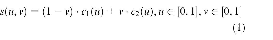
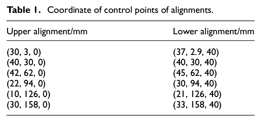
Ruled surface can be defined as a surface formed by a straight generatrix sweeping along the baseline in 3D space. The mathematical expression of ruled surface by upper and lower alignments is expressed as:
where
Set
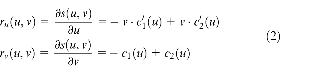
where
The norm vector is the cross product of
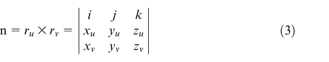
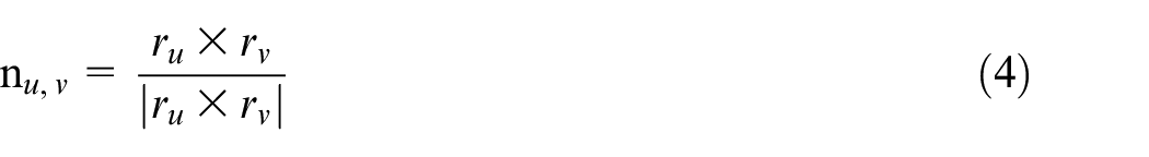
Typically, the norm vector represents unit norm vector, and the unit norm vector is calculated as:
Global flows of proposed method
Figure 1 shows the flowchart of all the process of the tool path regeneration method. It contains three main steps. Firstly, the error distribution is obtained by calculating the errors between theoretical points and measuring points. Then, the normal offset value and the norm vector of the tool path are calculated by fitting functions established by the error distribution and the norm vector of the surface. Finally, regenerative tool path is obtained by offsetting the cutter locations.
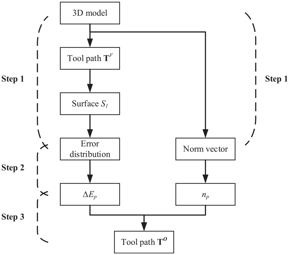
Flowchart of proposed tool path regeneration method.
The tool path regeneration method
Because of the variety sources of error and the effects of the coupling of the error sources, it is difficult to predict the error distribution accurately. An improved tool path regeneration method is proposed in this paper, which can be applied in five-axis flank milling of ruled surface. The internal mechanism of the proposed method is that the feature of the error distribution stays constant by making the cutter orientation unchanged, while the average error is decreased by offsetting cutter location.
The tool path is generated by varieties of methods based on the cutting contact curve. In ideal conditions, the cutting contact curve of the cutter is closed to the straight generatrix of the surface infinitely. However, the actual machining process is complicated, and the formation of geometric error is controlled by varieties of conditions. In this paper, the model between error sources and actual error distribution is regarded as a black box. On the one hand, the tool deformation accounts for a small proportion among all error sources. 5 On the other hand, the errors caused by cutting force is a small proportion of the machine centers 26 and the tool deformation can be neglected because of the slight material removal and low cutting force in the finish machining process. Therefore, the error distribution is nearly linear in the v direction.
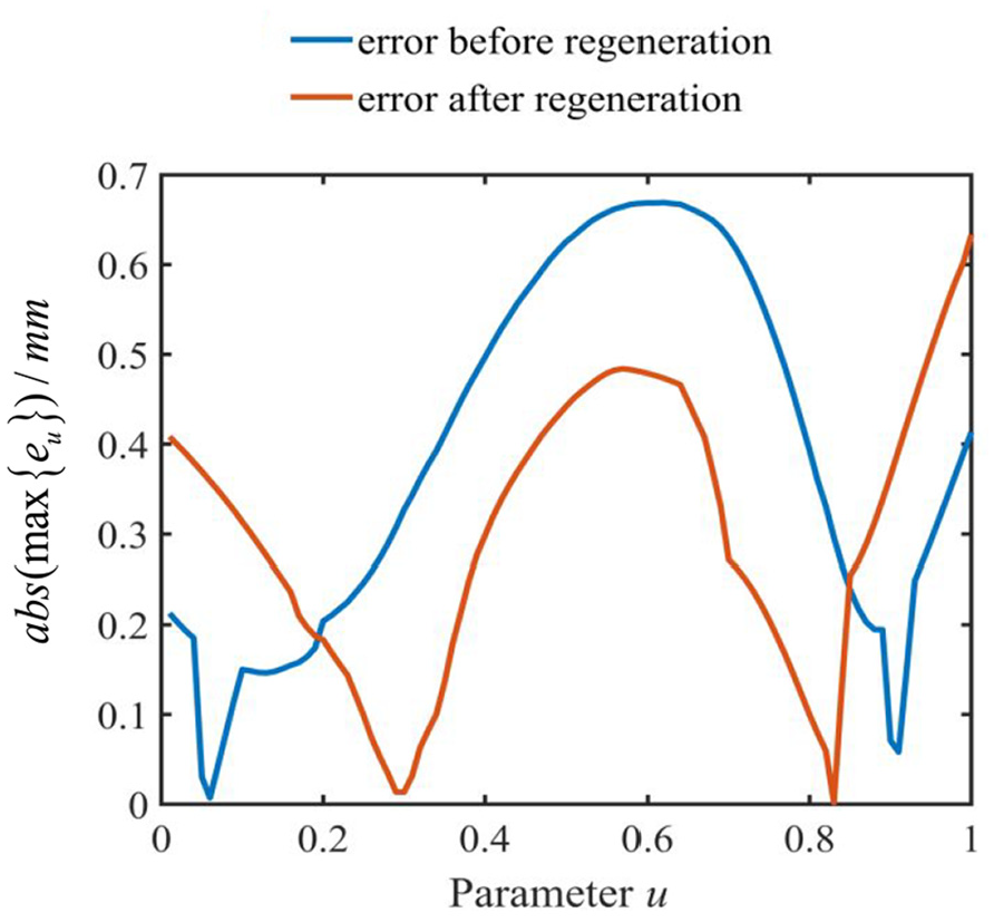
The variation of cutter location hardly influences the black box, while the cutter orientation affects kinematics characteristics of the machine tool significantly, which will change the form of error distribution. So, the cutter orientation stays constant in this paper. As shown in Figure 2, the
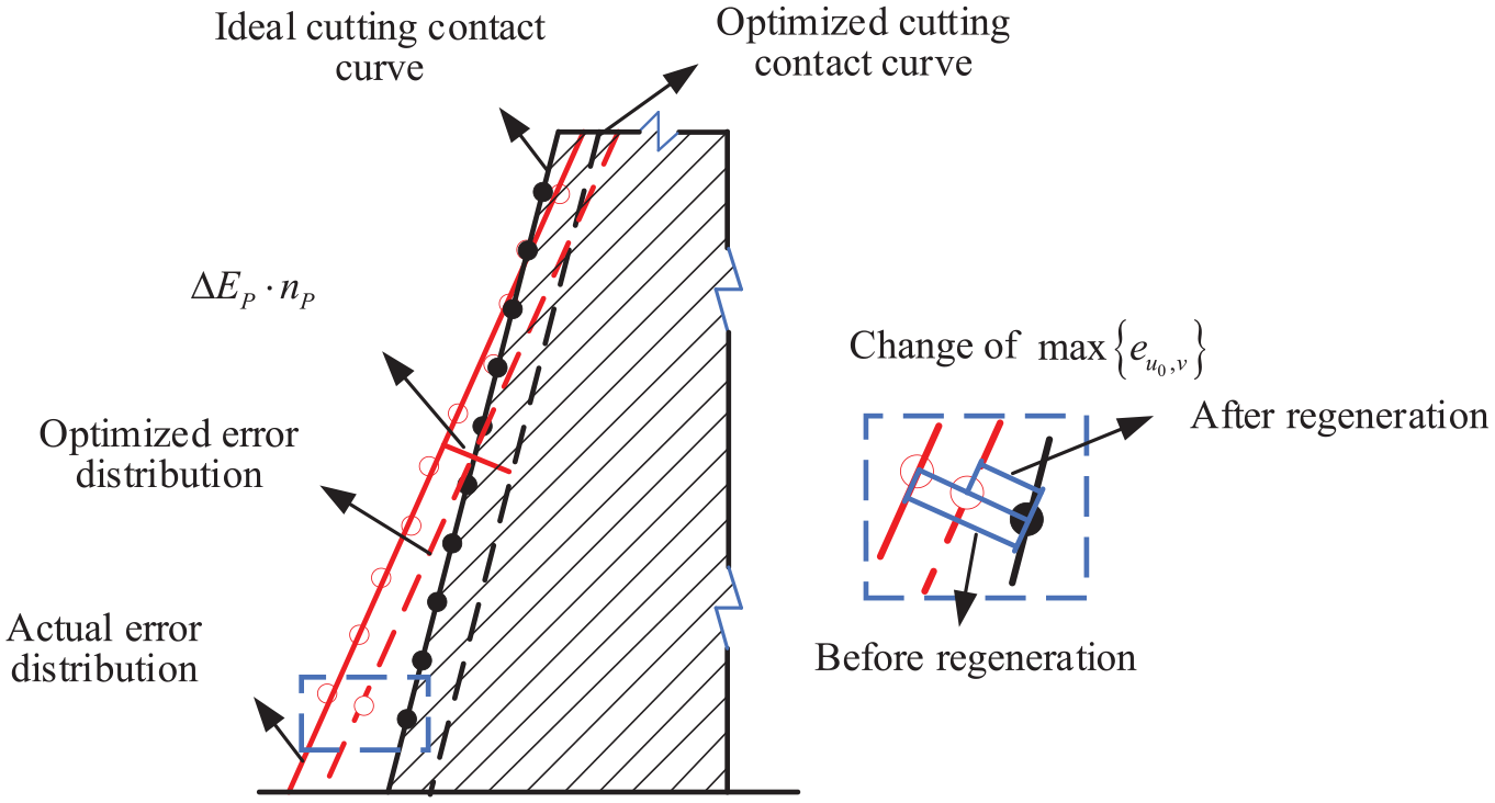
Comparison of error distribution at u0 section before and after tool path regeneration.
Calculation of normal offset value and normal vector of the tool path
It is fundamental to acquire the actual error distribution of the machined surface before tool path regeneration. Error distribution is obtained by calculating the deviation between theoretical points and measured points.
The point-to-surface distance is replaced by error in the paper. Error is the basis of the accuracy of the machined surface and the quality of the tool path generation. The coordinates of theoretical points are expressed as
where
and
The value of

where
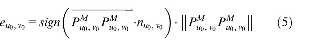
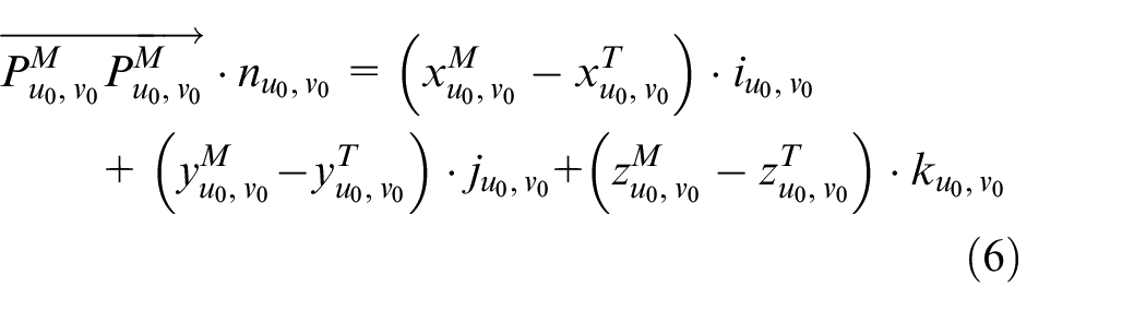
Normal vectors of the surface can be calculated by substitute v = 0.5 into formula (4). The error
Cutter location and cutter orientation are generated by variety conditions in CAM (Computer-Aided Manufacture) software. The actual cutting contact curve cannot be depicted by the error distribution directly, therefore, it is important to calculate the offset value

where
The objective equation of multi-peaks Gaussian fitting is expressed as:
where Y and X are variables of the fitting equation, K is the number of peaks of the data,
Tool path regeneration
Generally, the tool path containing cutter locations and cutter orientations is generated by CAM software, and then the post-processor converts the tool path into a NC program which can be recognized by a certain machine tool. The tool path regeneration is realized by modifying cutter locations.
Assuming the former tool path
where
Experiment and results
Setup of experiment
To verify the validation and accuracy of the proposed tool path regeneration method of ruled surface, a machining experiment is conducted on a five-axis machine center DMU-60 mono BLOCK with rotary axes B and C. The ruled surface is designed and the tool path is generated by the CAM software Unigraphics (UG). The NC codes are generated by Unigraphics (UG) with post-processor provided by manufacturer of the machine center.
Verification experiment is carried out for three times in order to reduce random errors. As shown in Figure 3,
Designed surfaces and original tool path.
Coordinate of control points of alignments.
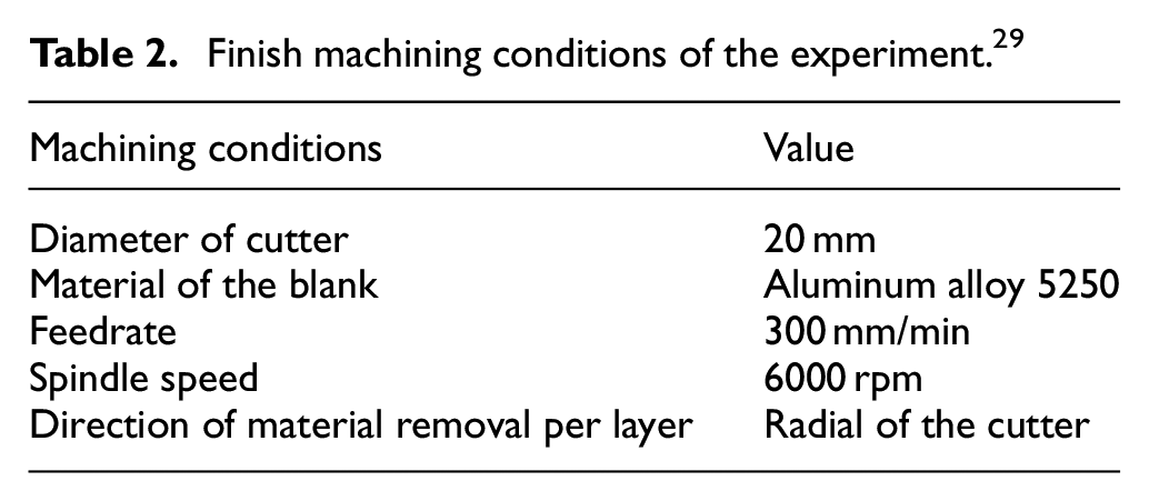
In order to reduce the non-synchronization of cutter location and cutter orientation, feedrate is limited relatively. 28 Finish machining conditions are listed in Table 2.
Finish machining conditions of the experiment. 29
The machining process is shown in Figure 4.
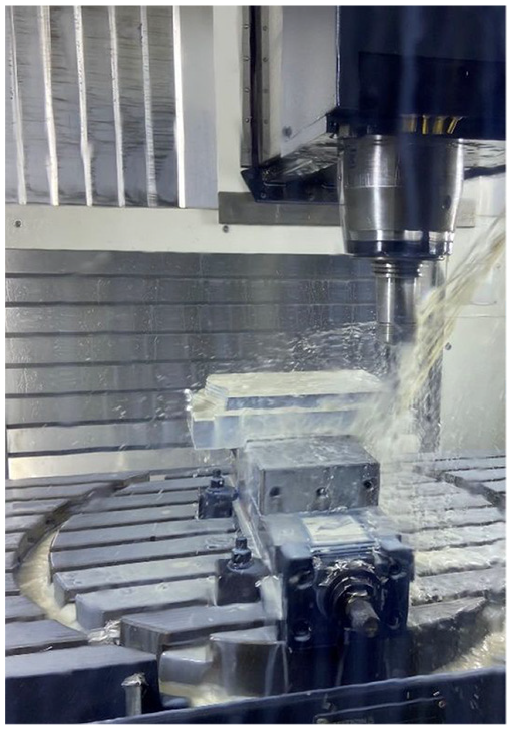
The machining process of the part.
The offline measurement experiment is carried out on a Daisy coordinate measuring machine (CMM, MPEE = 2.0 + L/300 μm), which was equipped with a touch probe with a diameter of 4 mm, and the coordinate measuring machine is shown in Figure 7.
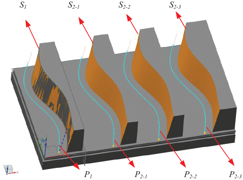
Surface S1 was machined firstly, and then it is transferred to the CMM after finishing process. 100 × 10 iso-parametric measurement points are distributed in surface S1. The machining error distribution was shown in Figure 5(a). In the figure, the negative value of the color bar denotes overcut, and the positive value denotes undercut.
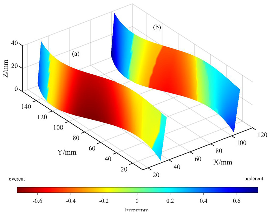
The error distribution of the surfaces: (a) the errors distribution of
According to the second section, 100 fitting lines are calculated with the average coefficient of determination 0.9582, which indicated that the linear fitting meet the assumption in Figure 2. 100 groups of
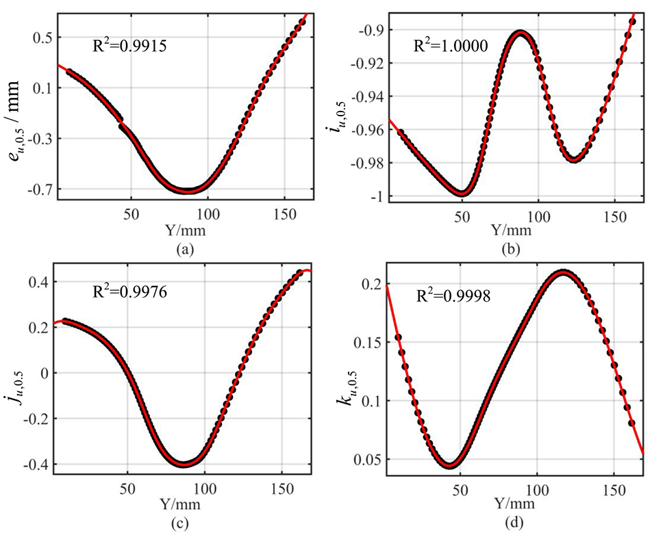
Results of multi-peaks Gaussian fitting: (a) the fitting results of
The final NC codes are got by converting the
Result of experiment
Surface
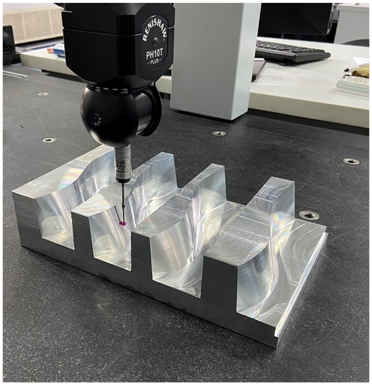
Measurement of the surfaces on the CMM.
The maximum standard deviation of the errors in
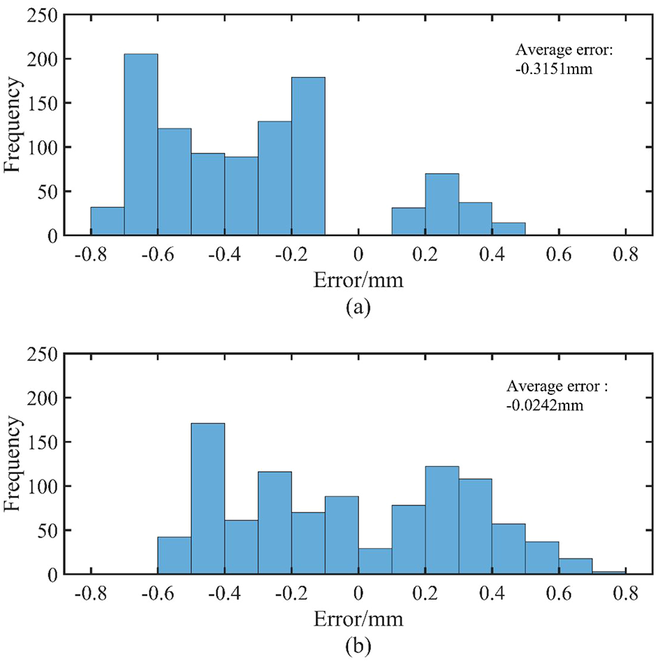
Histogram of the errors: (a) the errors of
The

where
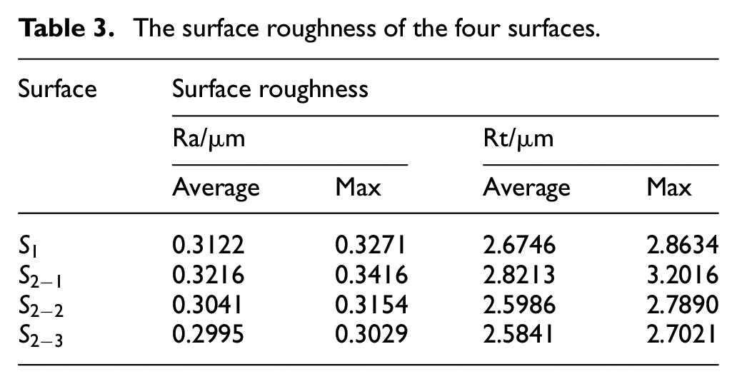
Due to the variety of cutter location, the value of material removal is changed, and the corresponding cutting force is changed, which may affect the surface roughness. The surface roughness is examined using a 2300 A-R profiler with a resolution of 18 nm/1200 µm. As shown in Figure 10, the white lines denote the sampling area on surface
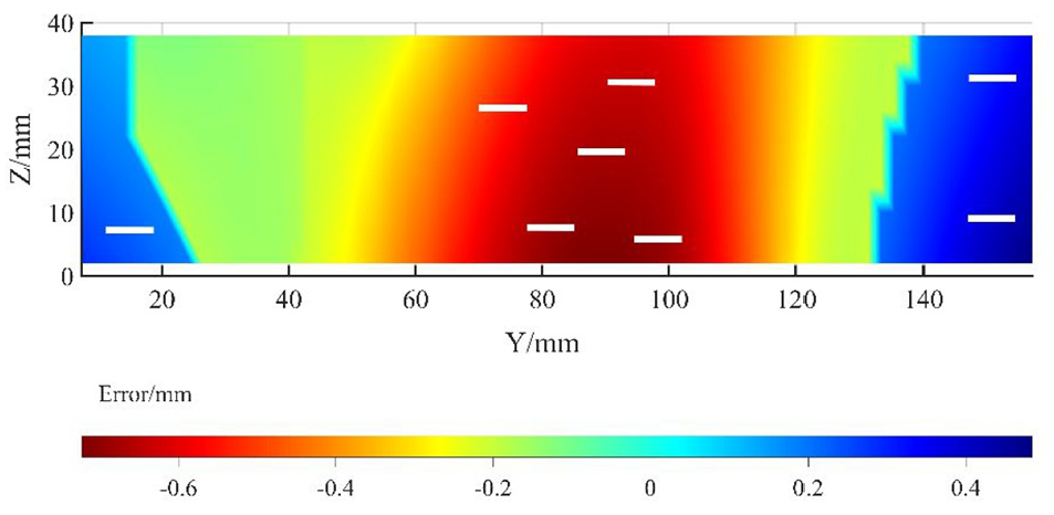
Sampling area on the surface.
The surface roughness shown in Table 3 reveals that the surface roughness does not change significantly and irregularly after tool path regeneration. The possible reason of this result is that the feed rate per tooth remain constant during regeneration, and the verity of cutting force do not play an important role in surface roughness.
The surface roughness of the four surfaces.
Conclusions
In this paper, a method of tool path regeneration for the ruled surface is presented to decrease errors by modified the tool path based on the actual error distribution of the machined part. At first, the errors at the middle of the straight generatrix on the machined surface are calculated by linear fitting of the errors distributed in u0, and the corresponding normal vectors are calculated by given formula based on the mathematical expression of the surface. Then, the errors and the corresponding normal vectors calculated in the last step are fitted with the increasing of a continuously increasing coordinate value. The value of normal offset of the tool path is calculated by the fitting function of the errors, and the normal vector of offset of the tool path is calculated by the fitting function of the corresponding normal vectors. Finally, the tool path is regenerated by the original tool path, the value and normal vector of offset of the tool path. The method is validated by an experiment carried out on a five-axis machine center. Results show that the average errors decrease 92.32%, and the surface roughness stays unchanged. The proposed method can effectively improve the accuracy of the surface.
Supplemental Material
sj-H-1-pib-10.1177_09544054221090043 – Supplemental material for Tool path regeneration in five-axis flank milling for ruled surface based on error distribution
Supplemental material, sj-H-1-pib-10.1177_09544054221090043 for Tool path regeneration in five-axis flank milling for ruled surface based on error distribution by Chenglin Yao, Gaiyun He, Yicun Sang and Yichen Yan in Proceedings of the Institution of Mechanical Engineers, Part B: Journal of Engineering Manufacture
Supplemental Material
sj-H-2-pib-10.1177_09544054221090043 – Supplemental material for Tool path regeneration in five-axis flank milling for ruled surface based on error distribution
Supplemental material, sj-H-2-pib-10.1177_09544054221090043 for Tool path regeneration in five-axis flank milling for ruled surface based on error distribution by Chenglin Yao, Gaiyun He, Yicun Sang and Yichen Yan in Proceedings of the Institution of Mechanical Engineers, Part B: Journal of Engineering Manufacture
Supplemental Material
sj-H-3-pib-10.1177_09544054221090043 – Supplemental material for Tool path regeneration in five-axis flank milling for ruled surface based on error distribution
Supplemental material, sj-H-3-pib-10.1177_09544054221090043 for Tool path regeneration in five-axis flank milling for ruled surface based on error distribution by Chenglin Yao, Gaiyun He, Yicun Sang and Yichen Yan in Proceedings of the Institution of Mechanical Engineers, Part B: Journal of Engineering Manufacture
Supplemental Material
sj-H-4-pib-10.1177_09544054221090043 – Supplemental material for Tool path regeneration in five-axis flank milling for ruled surface based on error distribution
Supplemental material, sj-H-4-pib-10.1177_09544054221090043 for Tool path regeneration in five-axis flank milling for ruled surface based on error distribution by Chenglin Yao, Gaiyun He, Yicun Sang and Yichen Yan in Proceedings of the Institution of Mechanical Engineers, Part B: Journal of Engineering Manufacture
Footnotes
Appendix A
Declaration of conflicting interests
The author(s) declared no potential conflicts of interest with respect to the research, authorship, and/or publication of this article.
Funding
The author(s) disclosed receipt of the following financial support for the research, authorship, and/or publication of this article: This study is supported by the National Natural Science Foundation of China (No.51675378).
Supplemental material
Supplemental material for this article is available online.
References
Supplementary Material
Please find the following supplemental material available below.
For Open Access articles published under a Creative Commons License, all supplemental material carries the same license as the article it is associated with.
For non-Open Access articles published, all supplemental material carries a non-exclusive license, and permission requests for re-use of supplemental material or any part of supplemental material shall be sent directly to the copyright owner as specified in the copyright notice associated with the article.