
Abstract
This article presents an approach based on screw theory and line geometry for the flank milling of dually defined twisted ruled surfaces. The designed surface is defined by a single-parametric dual nonuniform rational basis spline representation, while the tool’s axis is represented by a dual unit vector. The machining is performed along the dually defined lines and not per point since the ruled surface is represented by an aggregate of lines. The initial locating of the tool is accomplished via dual vector algebra and line geometry. Our method results in compact algorithms and fast tool-position calculation due to the single-parametric definition of the ruled surface and to the dual orthogonal matrix operator that is utilized to spatially associate the tool and the surface. The tool path determination is based on the offset of the designed surface. An iterative algorithm is introduced to ensure interference-free tool path that eliminates overcut. The introduced approach can be applied to twisted ruled surfaces and is appropriate for the machining of blades, propellers and turbines.
Introduction
Five-axis flank milling is one of the most promising yet demanding manufacturing technologies nowadays. In comparison to point-based machining, flank milling presents higher productivity, less tool wear and better precision. Five-axis machining has attracted the attention of both the scientific community and the industry for many years. This procedure presents various advantages over the three-axis machining, such as additional production efficiency, increased speed and the ability to machine complex surfaces. In five-axis machining, the flexibility in tool orientation is higher than the three-axis one. There are two main methods in five-axis machining: point milling and flank milling. In point milling, the cutting is performed with the bottom edge of the cutter, while in flank milling with the cylindrical surface of the cutter. In this way, flank milling requires less finishing work for the machined surface since no scallops are left behind. The operation of flank milling is well suited for the manufacturing of surfaces like turbine blades or impellers, while higher material removal rates and less tool wear are obtained. Although flank milling is gaining popularity nowadays, less research has been done compared to point milling methods.
There are several issues that arise in the five-axis flank-milling process. The most important ones are the tool positioning, the tool path planning, the calculation of tool interference and the error measurement. Tool path planning is a critical task and presents increased complexity in flank milling compared to the point one. Since in flank milling the cylindrical side of the cutter tool is utilized, the movement of its axis resembles the movement of a line in a three-dimensional (3D) space. The surfaces that are produced by such an operation are mostly ruled ones, and there is a considerable research effort focused on ruled surfaces and flank milling.1–9 Despite that the ruled surface is defined by the motion of a line, most of the relative research work is based on point representation of the designed surface and the tool path determination.
In tool path estimation for flank milling, it is critical to determine the error calculated between the designed and the manufactured surfaces. Several methods were proposed for error definition (error metrics), which usually fall into two categories: the radial methods and the parametric methods. 1 The radial methods involve the calculation of the distance between the surface of the tool (that is assumed to be stationary) and a point on a ruling of the surface. In the parametric methods, the error is calculated between the grazing curves and the corresponding points of the ruled surface for a specific parameter value. Usually, a closest point metric between the tool and the surface is used for optimization purposes. Error measurement is utilized to keep the estimated tool path in a specific error range.
Lartigue et al. 2 proposed an approach to determine the tool path in five-axis machining using the envelope surface. The tool path was represented via two curves defined by the trajectory of two points on the tool axis. Their method exploited the least squares criterion in order to minimize the deviation between the desired surface and the envelope one. This method was based on a conical tool and due to the least squares criterion is rather computationally intensive. Redonnet et al. 3 proposed a tangential positioning of the cylindrical tool to the ruled surface at three points. In order to calculate the tool positions for the approximation of the designed surface, they introduced seven transcendental equations that should be solved simultaneously. Because of this, their method led to high computational time requirements. Tsay and Her 4 presented a procedure for the five-axis machining of twisted surfaces with a cylindrical cutter. They calculated the undercutting in planes perpendicular to the rule line and utilized statistical analysis to minimize the geometric error. Menzel et al. 5 introduced a positioning strategy on three points of tangency calculated iteratively. The calculation of tool interference is even more demanding when shapes of complex geometry like propellers and turbine blades are to be machined.6,8–10 These ruled surfaces are usually not developable and present twists. The tool path calculation for the machining of this kind of ruled surfaces requires specific precision since the resulting products are highly valued.
Pechard et al. 11 proposed a method for globally minimizing the geometrical deviations between the envelope surface of the tool movement and the designed surface by deforming the Machining Surface, while preserving trajectory smoothness. They suggested that the energy of deformation of the Machining Surface is the more suitable indicator of the surface smoothness and used this criterion, which led to a large linear system of equations solved by Singular Value Decomposition. For the tool path planning in five-axis flank milling, a particle swarm algorithm was used to minimize the weighted sum of the overcut and undercut. 12 The authors claim that their method with multiple passes derives lower machining errors compared to single pass ones. Another important characteristic of the derived tool path in flank milling is the smoothness of the trajectory. Zheng et al. 13 proposed a method for smoothing the tool trajectory with a constraint on the resulting geometric error by solving a formulated multi-objective optimization problem. Their method simultaneously considers the geometric smoothness and geometric deviation, where the first characteristic was characterized by the strain energy of the cutter axis trajectory surface, while the geometric deviation was measured by the signed maximal orthogonal distance between the design surface and the tool envelope surface. Fallah and Arezoo 14 considered the locating of the workpiece toward eliminating the datum errors on the machined features derived by flank milling. In addition, a compensation module was developed and applied to the machining codes of the workpiece. They claimed that using this compensation module, the position, orientation and form errors are decreased considerably.
The presented methods used position-based representation and transformations for the derivation of the tool path in flank milling of ruled surfaces despite that the ruled surfaces are derived by the motion of line in the space. However, line geometry is proposed to represent the ruled surface because it is considered that it is natural since it is derived by the line motion, and this representation is compact leading to lower computations in deriving the surface characteristic or approximating a ruled surface.15–17 Recently, Sprott and Ravani 18 presented a method for cylindrical milling of ruled surfaces based on line geometry. They used the central normal to define the offset surface by displacing the generator in the direction of the central normal of the generator trihedron. They suggested multiple cutting passes to reduce the error.
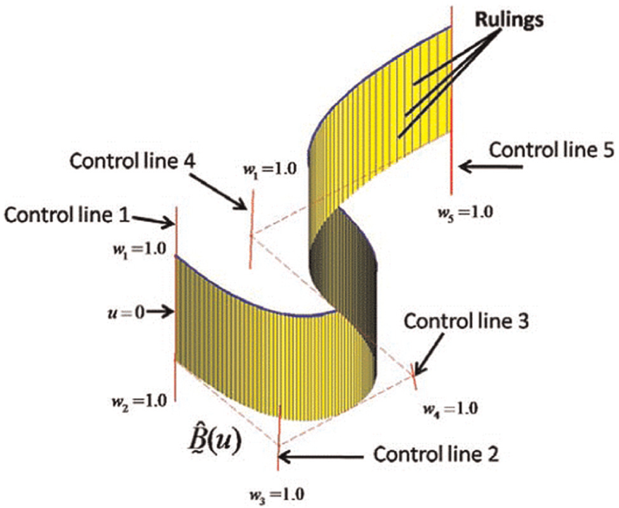
In this article, a new scheme for the flank milling of ruled surfaces is introduced, where the tool axis is positioned and oriented using line geometry instead of point geometry. The tool axis direction and position are expressed via dual unit vector based on line geometry and Plücker coordinates. 17 The surface to be machined is parameterized using the nonuniform rational basis spline (NURBS) basis functions and screw theory. The designed ruled surface is defined by interpolating directly dual unit vectors representing lines, which is a single-parametric surface, and its shape depends on the control lines. All the advantages of the NURBS such as shape control and the local modification property are also applicable and bequeathed to the dual NURBS ruled surface. The geometric relationship between the rulings of the surface and the tool axis is defined using the dual orthogonal matrix and dual unit vectors. Our approach is compact and robust since a mono-parametric definition of the surface is employed that lead to decreased complexity compared to two-parameter schemes. The spatial relationship between the surface and the tool is efficiently and simply defined resulting to low complexity computations. The movement of the tool axis is described in dual unit vector form based on line geometry and Plücker coordinates and by using the NURBS basis functions. The tool path is represented by the offset surface of the designed one via the dual orthogonal matrix. Our approach can find application on twisted, non-developable ruled surfaces due to the dual NURBS definition and therefore is suitable for the machining of complex shapes.
Dual NURBS designed surface representation
In this section, the line geometry representation of the designed surface to be machined is described. This representation is used to determine the offset surface to be swept by the tool axis as it is proposed in the next section.
The definition of the designed surface is based on the dual NURBS structure introduced by Papageorgiou and Aspragathos.
19
The control points are replaced by the control lines defined by the dual unit vector of the form
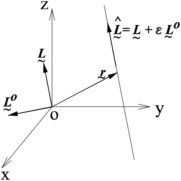
The Plücker coordinates of a line in the space.
For more information on the dual unit vector definition of a line in space, the reader is referred to the first section of Appendix 1.
The equation
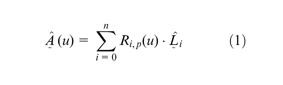
defines a NURBS ruled surface,
19
where

After the normalization of
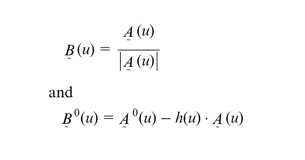
The derived dual unit vector
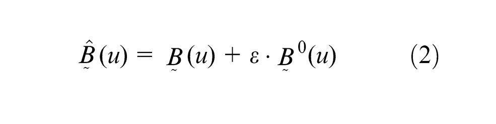
satisfies the Plücker conditions and represents a ruling of the ruled surface for a given value of
The dual NURBS ruled surface
There is a single infinity of solutions for the directrix curve of the ruled surface expressed by
where
and
The position vector
Using the position vector
where
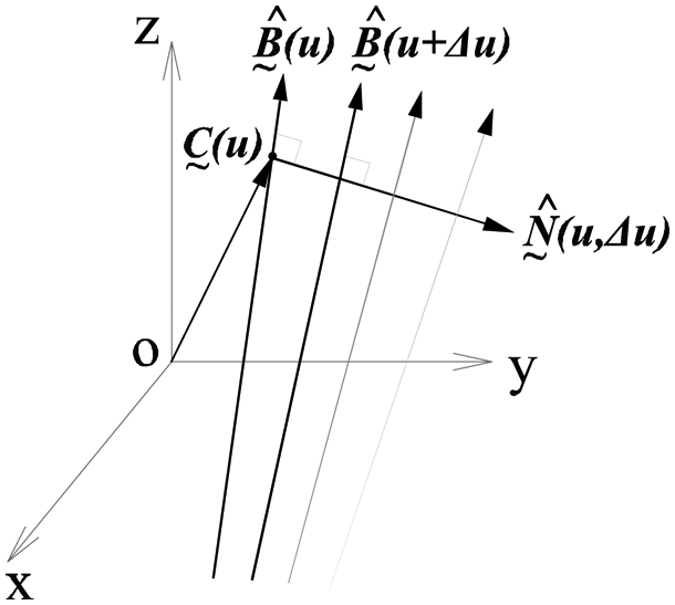
Central tangent, central normal and striction point.
The “distance” between two successive rulings, for example,
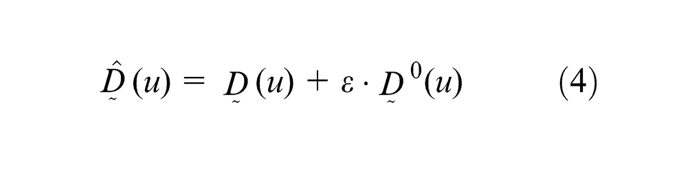
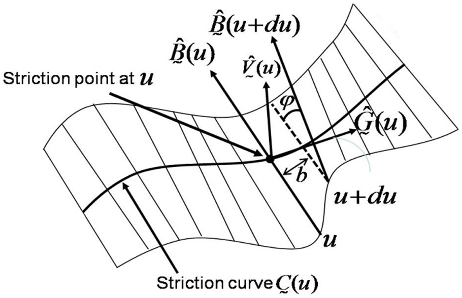
The expression of the ruled surface in equation (4) based on the striction curve has some rich geometric characteristics. The striction point of the dual unit vector surface representation has enough freedom to hold three-point vectors simultaneously. Thereby, extra information can be stored into the expression, such as the tangent vector and the normal vector. Therefore, all the essential surface properties are calculated, stored and represented by dual unit vectors. In Figure 5, a ruled surface parameterized with the striction curve as the directrix one is illustrated. By this parameterization, the surface representation is performed in the “neighborhood” of the striction curve.
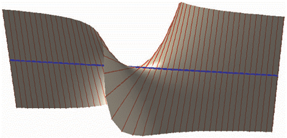
Ruled surface and striction curve (blue line) as the directrix.
It must be noticed that cones and cylinders are excluded from this expression. The striction curve of a cone collapses to a single point, while all the rulings for a cylinder are parallel to each other. The main reason for the parameterization of the ruled surface based on the striction curve is that it allows an easy and robust way to locate the tool’s axis relatively to the rulings of the designed surface.
Tool location relative to a ruling
Determining the suitable tool location relative to a ruling is an essential procedure for the successful machining of parts. For the twisted surfaces, the twist defined by the angle between two normal vectors to the surface on the end of a ruling is not zero. A twisted ruled surface is illustrated in Figure 6 with the normal vector directions that are not coplanar. In the developable (nontwisted) ruled surfaces, all the surface normals along a curling are coplanar. In flank milling of a twisted ruled surface, the machining error is unavoidable since the tool cannot be located tangent to the surface along a ruling.
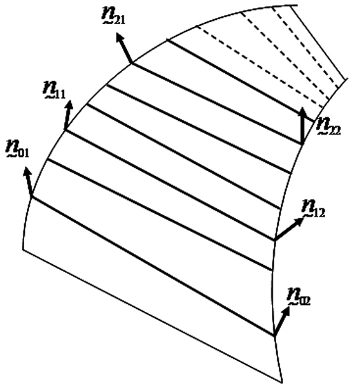
Twisted ruled surface and its normals.
For the positioning procedure, several strategies have been proposed trying to minimize the deviation of the machined surface relative to the designed one. A positioning strategy was presented, which placed the tool tangential to the two boundary curves on a ruled surface. 5 Redonnet et al. 3 introduced a technique for the positioning of the tool tangential to the ruled surface at three points by changing the angle between the tool axis and the ruling. Their approach requires rather high computational time due to the need for simultaneous resolution of many equations. A similar three-point strategy for the positioning using the envelope surface of the cylindrical cutter was proposed by Gong et al. 8 They utilized the offset surface of tool axis trajectory surface via a kinematics approach in order to produce the tool path. Senatore et al. 9 proposed an envelope surface approach for the positioning of the tool, utilizing the directrices of the ruled surface.
The positioning of the tool is very important since it affects the error between the machined surface and the designed one. If the shape of the tool is cylindrical, the tool orientation vector should be parallel to the corresponding ruling line distanced by the tool’s radius. However, for a twisted ruled surface, this method does raise interference problems. The overcutting can be avoided if the offset distance is altered, but even though the overcutting is eliminated, the tool undercutting could be increased. The ideal location for the tool would be to offset the ruling in the direction of a surface normal at a distance equal to the radius of the tool. However, the normals may vary along the ruling, and the tool starts to diverge from the designed surface.
In this article, the relationship between the tool’s axis and the ruled surface is defined via the dual orthogonal matrix operator. The introduced positioning strategy is suited for the twisted ruled surfaces. Our method includes the offsetting of the tool’s axis by a distance equal to the radius of the tool at the striction point in the direction of the normal vector at that point. In this way, we are eliminating the possibility for overcut since the apex of the curve is located at the striction point.
Let
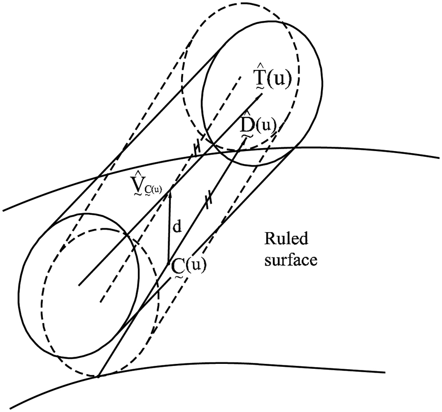
The tool’s axis relative to the surface’s ruling.
The tool’s axis
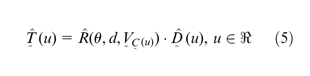
where
Tool path generation
In this section, a procedure for the tool path generation is presented. The designed surface rulings are offset by the radius of the tool with respect to the surface’s normal at the striction point. The resulting surface is defined by the tool’s axis locations before the tool path correcting procedure that modifies the tool’s axis locations based on an interference-free algorithm presented in section “Tool path correction procedure.”
Offset surface
In general, the offset surface
where
Intersection calculation
The calculation of intersection between the tool and the surface to be machined is a complicated procedure that involves the identification of the tool’s orientation with respect to the designed surface. A correction procedure is introduced in the next subsection to eliminate the overcut providing an interference-free tool path at every step of the tool. This is accomplished by controlling the orientation of the tool’s axis at every ruling of the offset surface for a given step.
Two dual unit vectors intersect when the dual component of their dual scalar product vanishes. This property is very useful but is not enough for a unique identification of interference in the tool path determination. Since the definition of the tool’s axis is based on dual unit vectors, a relationship between line and point geometry has to be established. It is required to have the position vector of any point on that line as well as the length of the line. We follow the line-segment representation proposed by Ravani and Wang, 16 as it is compact and defined in terms of Plücker coordinates.
In this article, we adapt their approach in order to define a line segment in dual unit form. Let us consider the line
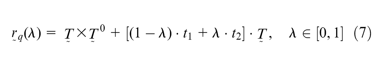
where
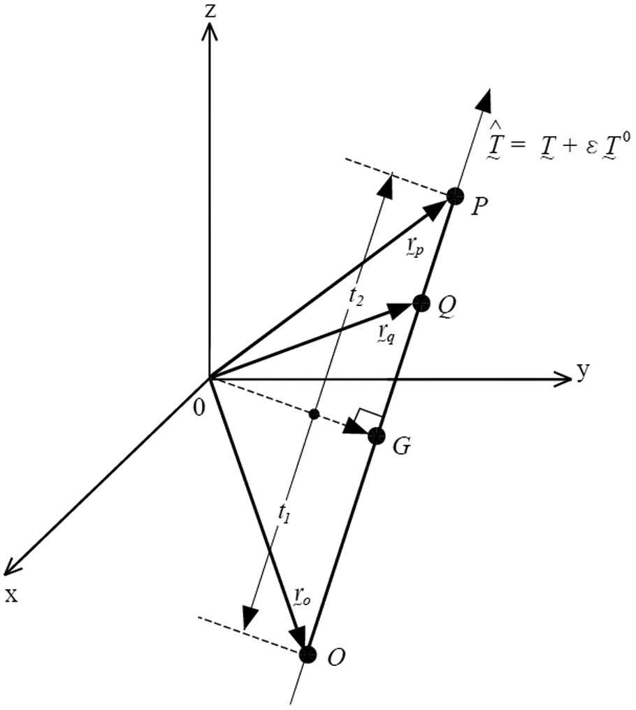
Dually defined line segment OP with respect to G.
This way, the length of the tool is also considered during the intersection verification of the positioning procedure. The procedure starts with the offset surface
The points that belong both to the tool and the offset surface are also identified via
Initial positioning of the tool’s axis with respect to the offset surface
where
For each tool axis location
in a specific interval of
The intersecting rulings of the offset surface are identified via equation (9), when the dual part vanishes. Practically, when the dual part is under a very low threshold. The intersection checking is complete when the intersection point is between the end points of the tooling given by equation (7).
Tool path correction procedure
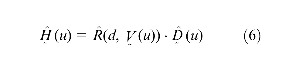
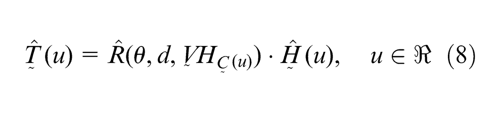
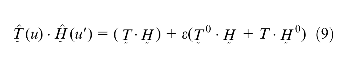
The tool’s positions that interfere with the offset surface are recalculated. Using equation (8)
The initial designed surface is given by
The offset surface
The tool’s axis
The intersecting rulings between the tool path surface and the offset one are identified and stored.
The tool path is then recalculated only for the intersecting rulings via the equation
The final surface
In Figure 9, an illustrative example of the algorithm is presented. Figure 9(a) presents the designed surface
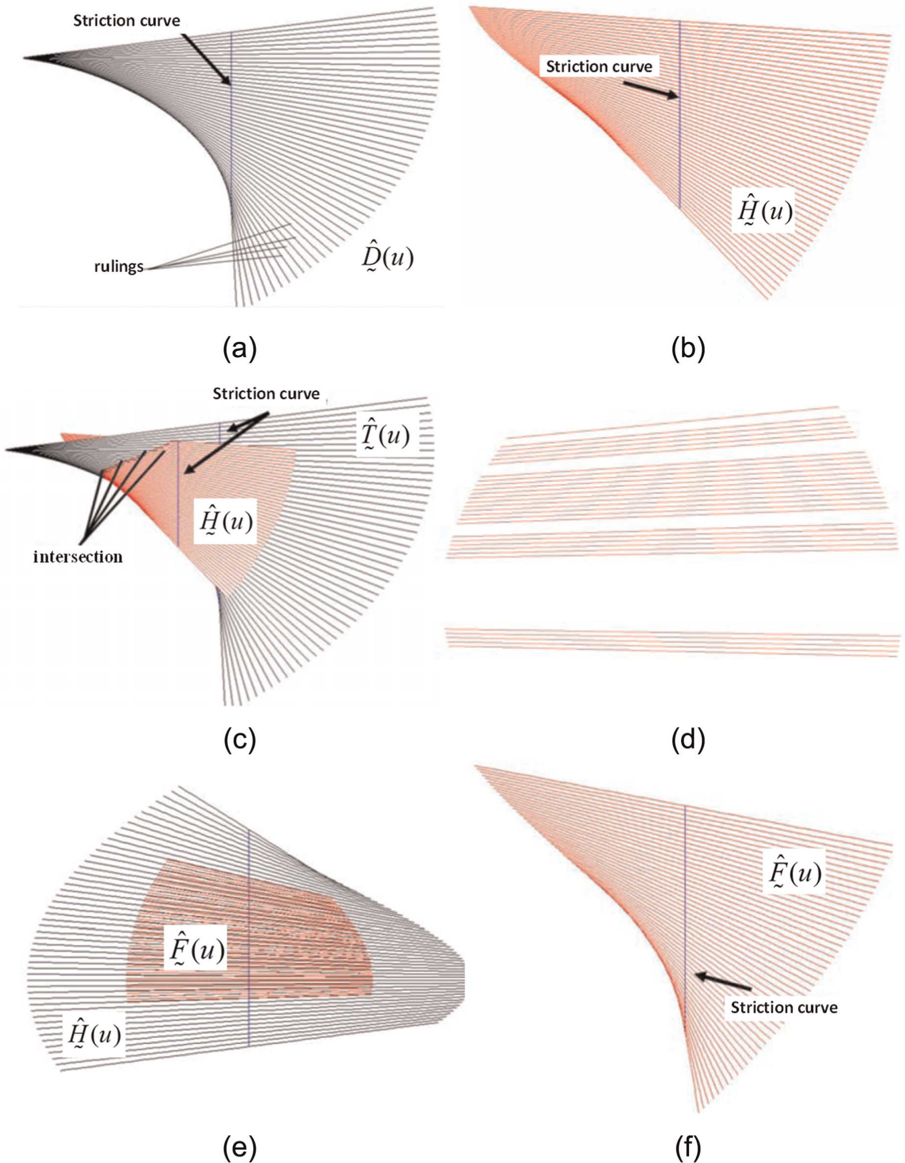
Illustrative example of the algorithm (a) the designed surface; (b) the offset surface; (c) the intersection of the offset surface with the tool axis surface; (d) the rulings of the offset surface intersecting with the tool axis; (e) the truncated final tool axis surface with the offset surface and (f) a view of the final tool axis surface.
Error metric
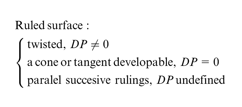
The accuracy of the twisted ruled surface flank milling depends on the radius of the tool, the distribution parameter (DP) and of the approximation of the initial surface, which is determined by each method for the tool path calculation. Most of the methods appeared in the literature are based on point definition of the surface and the tool, so the definition of the milling error is point-wise defined. In this article, the error is defined by the calculation of the deviation of the tool path from the offset of the given twisted ruled surface. This could be translated to point-wise defined error by the calculation of the deviation at the ends of the tool using the equations presented in section “Intersection calculation.”
The aforementioned deviation is given by the dual distance between the corresponding rulings of the offset surface given by
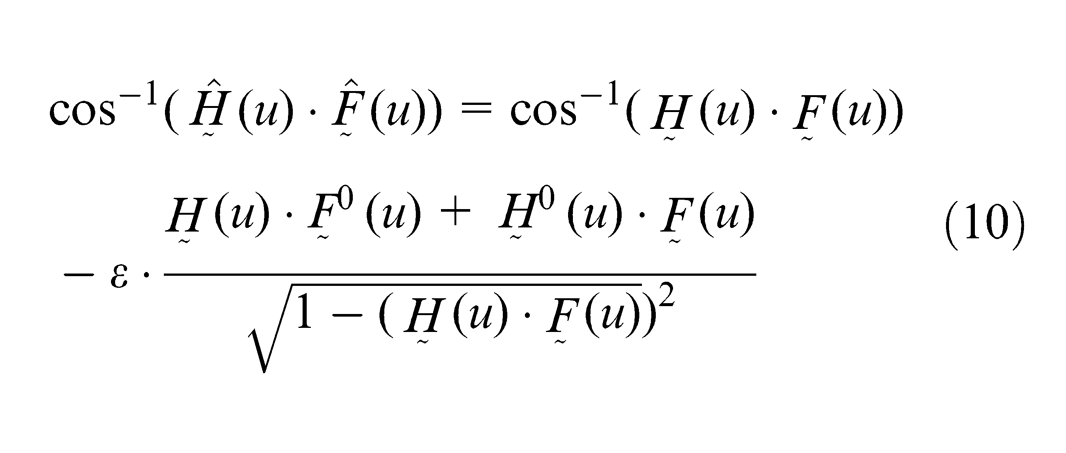
In this way, the distance between the initial surface and the approximating one is being measured by calculating the relative distance of the dually defined lines. Obviously, the distance
Discussion of results
The proposed algorithm was applied many times to the given twisted ruled surface in Figure 9 with a tool with different radius each time to investigate the effects of the tool radius size to the error. For each tool radius, results are obtained by applying the first part of the algorithm for the tool path given by the offset of the designed twisted ruled surface that should be produced after flank milling. The full algorithm with the second part for initial path correction is applied for each tool radius. The resulting error for the above-mentioned surface example is illustrated in Figure 10 for both corrected and uncorrected tool paths. For the uncorrected path, the overcut and undercut errors are quite high even for low tool radius; however, after the introduced correction, the undercut is eliminated, while the overcut is quite low for small tool radius.
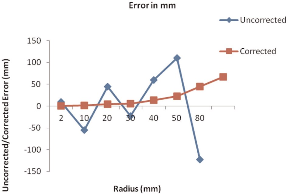
Error (mm) for various tool radius (before–after correction).
The corrected tool path does not contain any overcut since the algorithm eliminates any interference. This is not the case for the uncorrected tool path, where the intersections take place; overcut exists and appears with negative values as shown in Figure 10. For tool radius lower than 20 mm, the error is quite low and could be considered comparable to the results appeared in the literature, even if a direct comparison could not be done since there is not a benchmark, and the parameters affecting the milling error are too many and the error definition is different. The error presented in Figure 10 is indicative and could be further reduced by the reduction of the approximation step q used for the discretization of the offset surface and the step for the tool axis reorientation.
Since the undercut is not eliminated by the introduced flank-milling procedure, the material that remains can be removed easily using other procedures. The main advantage of the introduced procedure is the elimination of the overcuts that cannot be corrected.
The presented method for the determination of the initial and the corrected tool paths is based on dual line transformation, while the checking of intersection between the tool and the rulings is based on checking the value of the dual part of the dual product of dually defined lines, which are straightforward procedures. Therefore, computational time-consuming numerical procedures for solving nonlinear equations or for determining the optimal tool axis locations, like the ones presented in the introduction, are avoided. The determination of the intersecting rulings with the tool is based on sweeping the tool axis orientation in the neighborhood of its location determined in the initial positioning to determine the orientation without intersections. This means that the overcuts are eliminated and the undercuts are considerably reduced. The sweeping step of the angle is defined by the user, and the smaller the step, the lower the undercutting error and the longer the computational time. Even this procedure is straightforward without caring for convergence of numerical and optimization methods.
A simple and relatively fast method is presented for the approximation of the striction curve, which is a very important characteristic in twisted ruled surfaces. As it is recognized by Sprott and Ravani, 18 the location of the striction curve with respect to the tool path is very important for the reduction of the milling error. In the proposed method, the tool intersection with the rulings is detected by rotation of the tool axis around the normal to the surface at the striction point.
Another advantage of the proposed method is coming from the representation of the surface to be machined by a dual NURBS. It is well known that the NURBS are used widely for curves and surface representation due to their excellent properties for local control and the ability to handle large surface patches and represent analytical features. The dual line representation of twisted ruled surfaces is an endogenous representation to the definition of those lines since they are derived by the motion of line in the space. Therefore, a smooth position and orientation interpolation is obtained using NURBS with high flexibility and easiness in changing locally instead of globally the features of the surface and keeping its smoothness and continuity as well as controlling its features. In addition, the one-parameter representation of the surface and the derived tool path reduces the complexity compared to two-parameter representations.
On programming the tool motion
The programming of the tool path using the G-code based on the proposed approach is considered as a future work. However, it is worth to show the necessary coordinate transformations of the dual line representation of the tool axis to coordinates that are suitable for programming in G-code. In five-axis flank milling, new G-codes were proposed considering the point definition of the rulings moving on two curves. Lin and Koren 22 proposed two new G-codes: one for a conic surface and one for a ruled surface defined by two Bezier curves defined by four control points. In the second case, they proposed a G52 code to define the eight control points of the two Bezier curves for machining this ruled surface with flank milling.
For the case of dual line definition of the tool axis location proposed in this article, the Plücker coordinates can be easily transformed to the coordinates of two points on the tool axis and then we can adopt the G-code presented by Lin and Koren. 22 Alternatively, the Plücker coordinates could be used directly since the vector L represents the directional cosines, and the point of the coordinates of the tool positioning could be derived by the dual point definition. 21 With these two coordinate transformations, the dually defined tool axis as a function of the single parameter u by the proposed interpolation method can be transformed to the A, B and C angles around the x-, y- and z-axes, respectively, and to X, Y and Z coordinates that could be programmed using G-code commands. Of course, a post-processor should be developed to accommodate these transformations, which could be done in the future. It will be good to collaborate with people working in developing controllers for computer numerical control (CNC) flank-milling machines to derive new G-codes for the direct interpolation of dually defined tool axis motion.
Considering the limitations of the orientation of the tool axis, these could be easily incorporated to the proposed algorithm since the coordinates L, M and N of the tool axis unit vector defining its direction correspond to the direction cosines cos A, cos B and cos C. There are no special limitations imposed by the proposed approach for the ruled surface and tool axis representation as well as by the proposed algorithm for the tool path generation.
Conclusion and future work
In this article, a method for the flank milling of complex surfaces is introduced, which makes use of line geometry and screw theory. The designed surface is defined via the well-known NURBS basis functions and control lines instead of control points. This representation is geometrically rich, demonstrates low complexity and elegant formulation due to the fact that it is single parametric. The tool positioning is accomplished using the dual orthogonal matrix as the transformation operator for the tool’s axis. Furthermore, the tool path calculation is based on the offset of the designed surface. The main problem of tool accessibility is treated locally instead of globally, which is significantly easier to solve. Future study can include the development of CNC coding and changes to the control and software of the flank-milling machines for adopting the proposed line-based ruled surface representation and tool path determination and actual machining of blade surfaces such as turbines and impellers that present geometrical interest.
Footnotes
Appendix 1
Declaration of conflicting interests
The authors declare that there is no conflict of interest.
Funding
This research work was not supported by any specific grant coming from any public, commercial or non-profit agency. It is part of the authors’ duty for research work at the University of Patras.