
Abstract
Five-axis flank milling is the most commonly used processing method in the aviation industry for the machining of thin-walled parts with complex ruled surfaces. During machining, the tool/workpiece deformations caused by the cutting force often lead to surface errors on the machined components that severely affect the accuracy of the machining results. This article presents an iterative compensation strategy to reduce the tool/workpiece deformation-induced surface error during the five-axis flank milling of thin-walled workpieces by modifying the tool tip position and tool axis orientation. This approach can be implemented in four steps. First, a highly integrated cutter-workpiece engagement extraction method is developed for the construction of a flexible cutting force model that can follow changes in the process geometry. Second, the tool/workpiece deformations are predicted by the cantilever beam model and finite element model, respectively. Third, an off-line error compensation scheme is performed at each cutting location of the tool path to obtain the modified tool position. Fourth, the machined surface of the workpiece model is reconstructed, and the compensated machining code, which can be used directly for actual machining, is generated. A case study is presented at the end of this article, and the effectiveness of the present compensation strategy is verified by machining experiments.
Introduction
Thin-walled parts with complex ruled surfaces are widely used in the aviation industry. Five-axis flank milling is the primary processing method for manufacturing these components. 1 During machining, the tool/workpiece (T/W) deformations induced by the cutting force often have a negative influence on the shape and dimensional accuracy of the machined surface. 2 The multi-pass processing method is commonly used in engineering practice to ensure the machining accuracy of thin-walled parts, but this method will reduce the production efficiency considerably. A review of the literature illustrates that an off-line tool path compensation strategy can be considered as an effective method to obtain quality thin-walled workpieces without sacrificing productivity. In other words, single-pass machining will be reliable for practical use when the position of the cutter is modified according to the error data of machined surfaces. This article will focus on the study of an efficient compensation approach to reduce the force-induced surface errors in the five-axis flank milling of thin-walled workpieces.
A detailed review of the literature is presented first. Ratchev et al. 3 used a theoretical flexible force-deflection model to predict the force-induced errors in the peripheral milling of thin-walled structures, and they compensated for the errors by optimizing the tool path prior to machining. Then, Dépincé and Hascoët 4 presented a compensation method during the end milling that accounted for the effects of tool deflection during the generation of the tool path. At the same time, Wan and Zhang 5 and Wan et al. 6 developed an efficient algorithm for controlling the force-induced surface dimensional errors during the peripheral milling of thin-walled workpieces. In this algorithm, the cutter deflection and workpiece deformation are estimated by a cantilever beam model and a finite element model, respectively. Furthermore, Chen et al. 7 considered the coupling relation between the cutting force and the machining deformation in error compensation for thin-walled parts. Their study concluded that iterative compensation results in smaller machining errors, and the errors are more uniform. Similarly, Yue et al. 8 proposed a tool path modification strategy to compensate for the tool deflection–induced profile errors in the corner milling process. The compensated position of the cutter is calculated using an off-line compensation algorithm. More recently, many researchers have highlighted that a high-precision cutting force model is essential for obtaining satisfactory compensation results. 9 Based on this fact, Du et al. 10 presented an off-line tool path compensation procedure for reducing surface errors in the peripheral milling of low-rigidity workpieces. This procedure involves the use of an analytical force model based on the Fourier series, which makes the compensation process more convenient. As demonstrated by the above literature review, the combination of T/W deformations, an iterative compensation strategy and an efficient cutting force model are essential for this work.
In addition, with the increasing application of complex parts, an increasing number of researchers are focusing on the influence of the workpiece surface shape on the machining process. Rao and Rao 11 compensated for the static form errors caused by cutting force–induced tool deflections during the peripheral milling of variable curvature geometries. Their study demonstrated that the cutting force strongly depends on the workpiece curvature, and thus, variations in the surface errors occur along the tool path. Bera et al. 12 presented a methodology to compensate for the cutting force–induced surface errors during the end milling of tubular geometries by modifying the tool paths. This methodology takes both the tool deflection and workpiece deformation into account and adopts a flexible cutting force model that can follow changes in the process geometry caused by static form errors. Wei et al. 13 applied a form error compensation approach for the three-axis ball-end milling of a sculptured surface. The form error prediction can be performed without iterative calculation, but it is only suitable for surface deflection errors caused by tool deflection. Gao et al. 14 found an efficient means to reduce the machining deformation of thin-walled parts with curved surfaces and then proposed an error compensation method based on modifying the cutter location point. Gök et al. 15 compensated for the tool deflections at the ball-end milling of inclined surfaces. Although the above studies represent sound explorations in the processing of complex parts, the workpieces investigated in these studies were obtained through the three-axis processing method; as a result, their proposed compensation methods cannot be used directly for a five-axis machining process.
Even if there are some error compensation studies related to the five-axis machining already, they are difficult to apply for our research purposes. For example, Huang et al. 16 and Liu et al. 17 compensated for the T/W deformations in the five-axis flank milling of thin-walled parts based on on-machine measurement (OMM) error data. Wang and Sun 18 developed a methodology for error compensation during the five-axis spiral milling of blades; this methodology focused on the surface errors caused by residual stress but did not consider the force-induced T/W deformations. Ma et al. 19 presented a scheme to compensate surface errors in the five-axis ball-end milling of a sculptured surface. However, their scheme does not consider the workpiece deformation and does not explain the iterative computation between the cutting force and the tool deformation. In fact, the relative position between the tool and the workpiece can change erratically during the iterative compensation course, particularly for the five-axis flank milling process. In these cases, it is even more important to describe the geometric feature of the component accurately. Recently, Xu et al. 20 proposed a tool path planning scheme to control the geometrical errors in the five-axis flank milling of complex thick-walled parts and highlighted that the rapid extraction of cutter-workpiece engagement (CWE) is the basis for constructing a flexible cutting force model to perform the iterative compensation; this work considers some of these aspects in detail.
The remainder of this study is organized as follows. A novel CWE extraction method is introduced in section “A novel CWE extraction method.” The prediction of T/W deformations is presented in section “Prediction of surface errors.” An off-line error compensation strategy is developed in section “The iterative error compensation strategy.” The machining code is updated in section “Generation of the compensated machining code.” The experiments for compensating force-induced surface errors are described in section “Case study.” The last section provides the final conclusions.
A novel CWE extraction method
A previous study demonstrated that a multi-level compensation strategy is required to eliminate T/W deformation-induced surface errors during the flank milling of thin-walled parts. 21 In other words, the coupling relation among the tool offset, cutting force and machining deformation should be considered by iterative computation. In this case, a flexible cutting force model for identifying the variations in CWE is required due to deformations in the tool and the workpiece. The flexible cutting force model uses the calculation results of the rigid model to estimate the static T/W deformations and then the predicted values are adopted for the correction of the radial cutting depth and the determination of the updated CWE to predict the revised cutting force. The iterative computation of the cutting force and T/W deformations based on the updated CWE continues until the deformations converge to a stable value. For three-axis flank milling, the geometrical characteristics of the machined surface can be described by mathematical expressions, making the iterative scheme easy to implement. 12 However, for five-axis flank milling, because the machined surface is a complex ruled surface, it is difficult to recognize the instantaneous contact relationship between the tool and the workpiece over time.
To resolve the above issues, a novel CWE extraction method is proposed in this section. This method replaces the solid model with discrete coordinate points in the CWE extraction process and is thus more suitable for system integration. Figure 1 shows the procedure for the proposed CWE extraction method, which consists of the following steps:
With the help of computer-aided manufacturing (CAM) software, the tool path and corresponding cutting location (CL) file are generated. The instantaneous tool coordinate system (TCS) is established according to the tool position information in the CL file. The origin of the TCS is located at the tool tip, and its U-, V- and W-axes represent the instantaneous feed direction, machined surface normal vector and tool axis vector, respectively.
The point cloud data from the machined surface of the workpiece model are extracted, and the suitable point set {A} is identified by the given CL information, as shown in Figure 1(a).
The extraction process is shown in Figure 1(b). First, the coordinates of each point in point set {A} are described in the TCS, and the vertical distance from the point to the tool axis is employed as the limit condition to form point set {B}. Next, the cutting tool is dispersed into several tool chips along the axial direction. For the jth tool chip, the points located within the elevation range of the chip are extracted from point set {B} to form point set {C j }. Finally, the coordinate values of the points on both sides of the V-axis in point set {C j } are added and averaged, and the results are imported into point set {D j }.
The points in all sets {D
j
} are concentrated to form an instantaneous immersion profile. After trimming by the feasible contact boundary
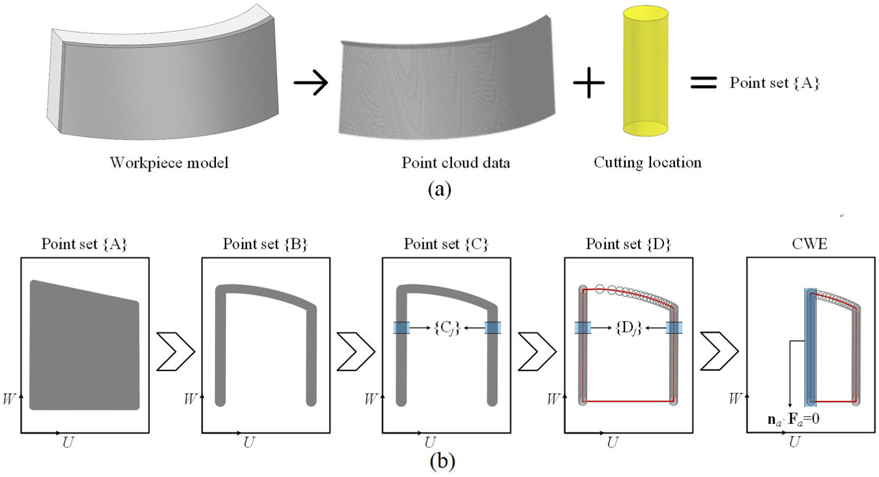
CWE extraction procedure: (a) determination of point set {A} and (b) the CWE extraction process.
The flexible cutting force model used in the five-axis flank milling process is constructed by integrating the proposed CWE extraction method into the general mechanistic force model. The essence of this method is to replace the machined surface with discrete coordinate points, and thus a few details are worth noting. The first is that all T/W deformations should be converted into tool displacements when calculating the updated CWE because of the fixed position of these discrete points. The second is that the computational accuracy of this method is closely related to the density of the point cloud data. In general, a higher density results in more accurate CWE extraction results but at the cost of reduced computational efficiency. For the model to have an appropriate density of point cloud to identify the T/W deformations, the distance between adjacent points

where
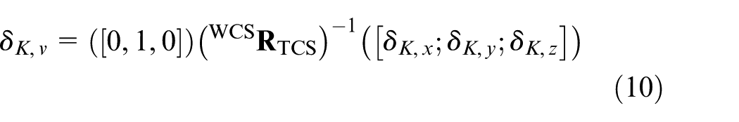
In addition, the global coordinates of the cutting force model are aligned with the Cartesian X, Y and Z axes of the workpiece coordinate system (WCS); as a result, the force values can be used directly to predict the deformation error of the workpiece.
Prediction of surface errors
In the flank milling process, the deformation error often occurs in the normal direction of the surface, which is also the V-axis direction of the instantaneous TCS. Therefore, the T/W deformations during five-axis flank milling can be simplified to a two-dimensional error in the instantaneous VW-plane. The deformations of the tool and the workpiece are computed independent of each other. When calculating the T/W deformations, both the tool and the workpiece are divided into several elements along the W-axis direction for the application of non-uniform cutting forces. The elevation of the axial tool disk elements and the thickness of the brick workpiece elements should remain consistent to ensure that the predicted T/W deformations can be directly transformed into the tool displacements. Because of the variations in local stiffness, the T/W deformations are not constant along the axial length of the cut. In general, the deformation of the cutting tool is greater closer to the bottom, whereas the workpiece exhibits the opposite tendency. Thus, for the five-axis flank milling process, the tool displacements include not only the movement of the tool tip position but also the rotation of the tool axis vector, as shown in Figure 2.
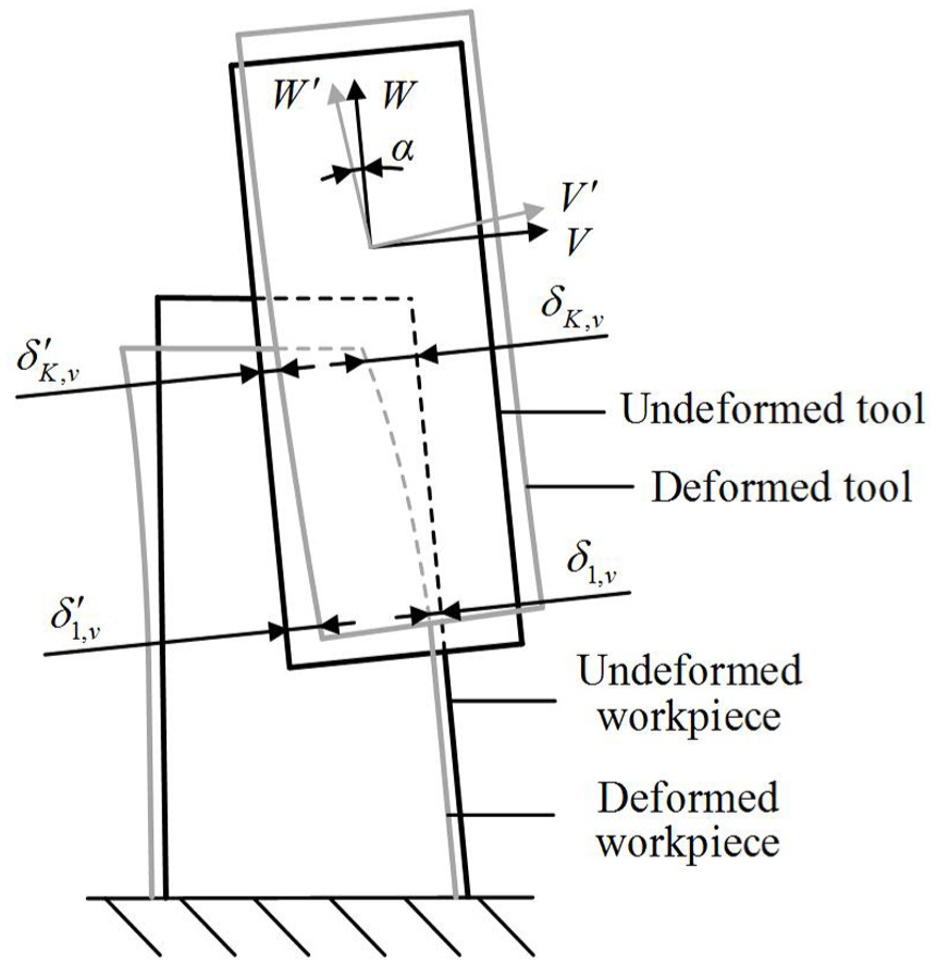
Deformations of the tool and the workpiece.
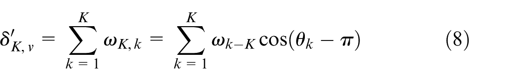
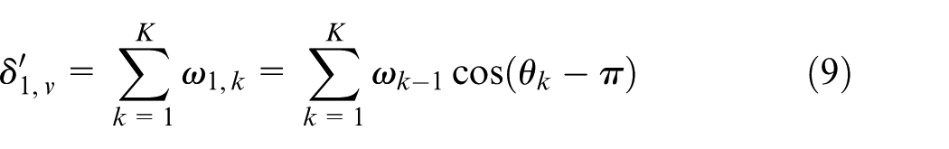
The symbols

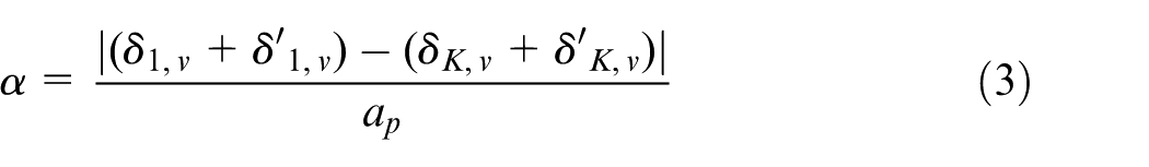
where
Then, the average deformation error
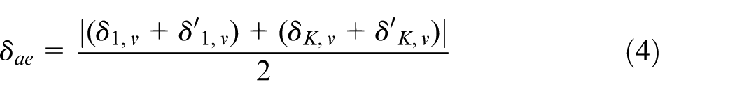
When the average deformation error between the two adjacent iterative calculations satisfies equation (5), the machining deformation is said to reach the equilibrium state

where m represents the current iteration steps for the surface error prediction.
Once convergence is reached at a given tool position, the stable tool displacements are regarded as surface errors that can be used for subsequent deformation compensation.
Calculation of the tool deformation
The tool deformation is calculated using the cantilever beam model with non-uniform cutting forces acting on axial tool disk elements. The model assumes that the cutting tool is a cantilever beam with one end fixed and one end suspended. The stiffness of the beam in the W direction is typically treated as adequate, and the deformation in the U direction has only a slight effect on the resulting surface errors. Thus, only the deformation in the V direction is typically considered. The total deformation of individual axial tool disk elements in the V direction can be calculated via the cantilever beam formulation and the superposition of the deformations.
Figure 3 shows the calculation principle of the tool deformation. The action of the cutting force on each tool element consists of three components, namely, the axial force
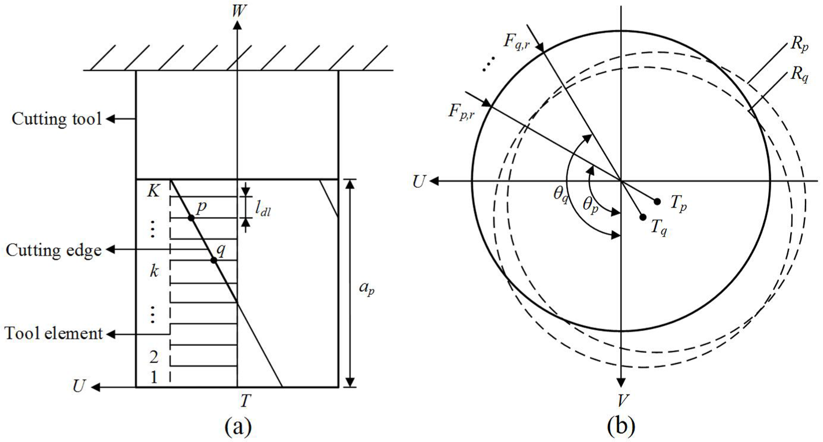
Diagram of the tool deformation calculation: (a) discretization of contact area and (b) tool deformation caused by radial force.
If there is no cutting force, then the initial position of the tool element is shown as the solid circle in Figure 3(b). If there are radial forces in different directions, the position after deformation is shown as the dotted circle in Figure 3(b). According to the cantilever beam deflection theory, the
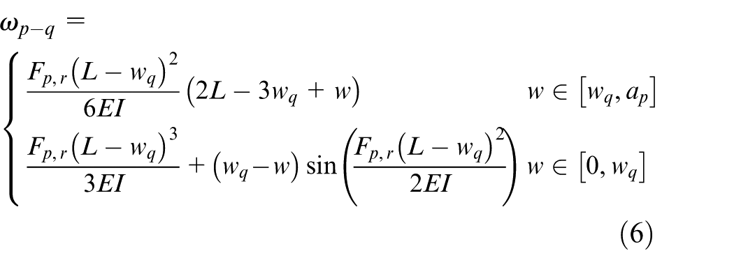
where E is the elasticity modulus of the tool material, I is the polar moment of the inertia of the tool and
Then, the

By adding the deflections of element q in the
Calculation of the workpiece deformation
The ANSYS parametric design language (APDL) is used in this study to predict the deformation of the workpiece. APDL is a parametric design language by which the finite element analysis (FEA) model of a workpiece is built according to specific parameters, and the iterative calculation of the machining deformation can be performed rapidly via several program statements. 10 By importing programs based on APDL into ANSYS software, the loading and unloading of cutting forces at discrete tool positions and the iterative algorithm, which considers the coupling effect between the cutting forces and T/W deformations, can be implemented automatically.
Figure 4 shows the calculation principle of the workpiece deformation. After the computer-aided design (CAD) model of the workpiece is imported into ANSYS software, the material attributes are defined, and efficient hexahedral units are used to divide the grids. The length of the grid
where
Illustration of the loading cutting force in the FEM model.
The iterative error compensation strategy
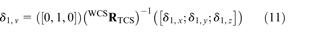
The primary purpose of the off-line error compensation strategy is to reduce the machining deformation caused by the cutting force, and the most direct way to perform this scheme is to modify the tool position based on the calculated tool displacements. However, errors cannot be entirely avoided using the direct movement of the tool position by an amount equal to the predicted tool displacements in the opposite direction. As the cutting condition changes, the actual compensation values must be modified iteratively such that the final surface error can fall within the given tolerance band. Figure 5 shows the mirror image method for the iterative compensation of the machining deformation in the five-axis flank milling process. The procedure for this method can be summarized in the following steps:
For a given CL, the value of the surface error is predicted and is represented as
The nominal tool position is taken as a mirror, and the deflected position of the cutter is mirrored by the amount
The convergence of the procedure is determined by comparing the average deformation error difference
If not, the revised surface error is calculated iteratively according to the process described in step 2. The procedure will end when the average deformation error between the two adjacent iterative calculations satisfies
Mirror image method.
Referring to the modified mirror image method, the entire compensation process used for five-axis flank milling can be summarized as shown in Figure 6. Using the convergent T/W deformations as the surface error, the modified tool position includes two parts, namely, the movement of the tool tip and the rotation of the tool axis. This operation allows for the control of the deformation error at both ends of the axial length of the cut, as shown in Figure 7.
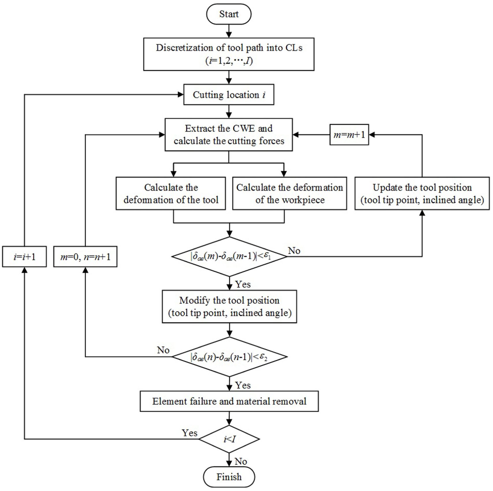
Flowchart of the proposed error compensation strategy.
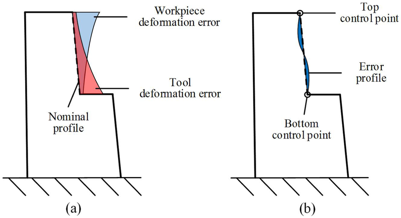
Illustration of the compensation principle: (a) uncompensated error and (b) compensated error.
In addition, the rigidity of the machined parts decreases significantly with the removal of materials, increasing the workpiece deformation error. Thus, when the iterative compensation on the individual CL is complete, the “element birth and death” technique is applied to simulate material removal. The process in which the cutting edge cuts into and out of the workpiece is performed by the loading and unloading of the cutting force, and the loading time
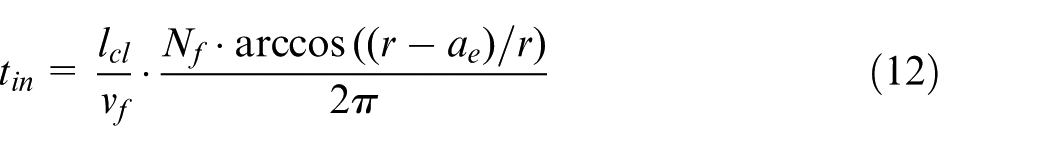

where
Once the procedure is completed at a given CL, the iterative compensation process is repeated for the next CL along the tool path until the machining is complete.
Generation of the compensated machining code
The surface machining error can be compensated by modifying the tool path to increase the machining accuracy of the surface. However, considering the computational efficiency, the number of CLs corrected by the compensation algorithm is less than the number of CLs actually used in the machining process. Thus, the machined surface must be reconstructed according to the modified tool position data and then by generating the compensated machining code. This process can be implemented through the following steps:
Based on the modified tool position of each CL, the instantaneous contact line between the tool and the workpiece is calculated as the section line of the reconstructed surface.
All the section lines are imported into the CAD software to synthesize the ruled surface. After smoothing, the compensated surface of the workpiece is obtained.
The workpiece model is updated through the application of the compensated surface and then the modified tool path is re-programmed using the CAM software. Next, the compensated machining code is generated after post-processing.
When the compensated machining code is applied to the actual milling process, the T/W deformations caused by the cutting force can be compensated at once.
Case study
Machining experiments
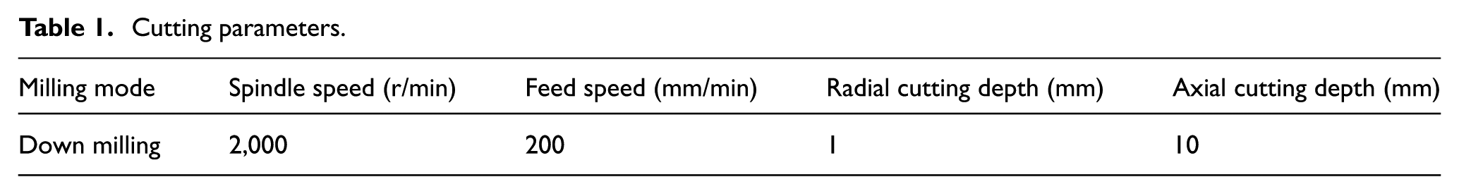
Machining experiments are performed to verify the effectiveness of the proposed compensation strategy in the five-axis flank milling of thin-walled workpieces. This case study employs the S-shape test piece as the experimental object. The S-shape test piece can accurately capture the typical features of thin-walled aerospace parts, and it is thus widely used in the aviation industry to verify the machining accuracy of five-axis machine tools. 22 The first step of the machining experiments is to obtain two high-precision S-shape test pieces with conservative processing parameters. The overall size of the test piece is 260 mm × 200 mm × 30 mm, and the wall thickness is 5 mm. Then, two final machining operations are performed on both S-shape test pieces separately, one with the general tool path and the other with the compensated tool path, as shown in Figure 8(a). The cutting parameters used for the final machining operations are identical, as shown in Table 1.
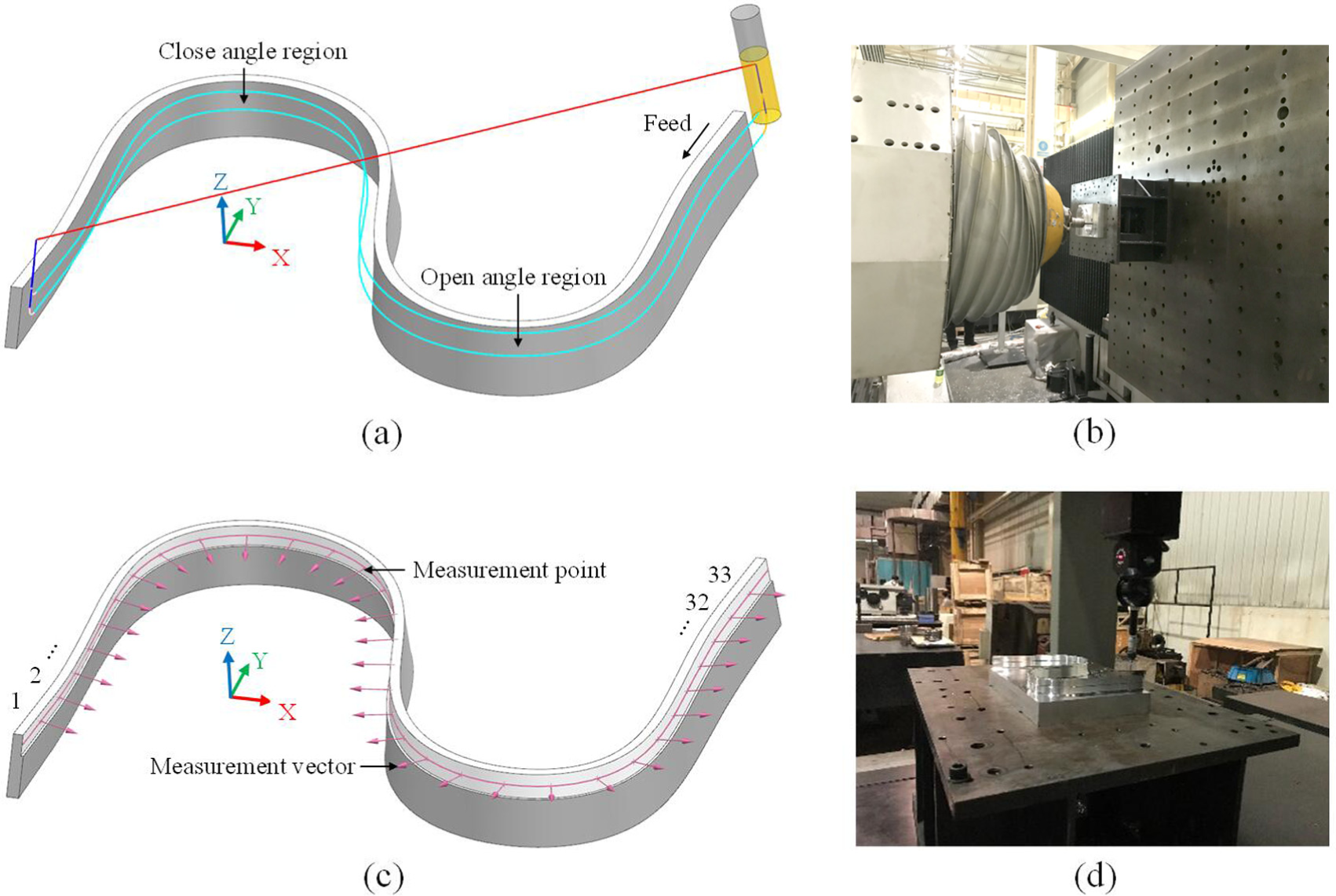
Machining and measuring of the S-shape test piece: (a) machining path, (b) machining process, (c) measuring points and (d) measuring process.
Cutting parameters.
All the machining experiments are performed on a 3P(Pa)S five-axis hybrid machining center, as shown in Figure 8(b). The maximum tool swing angle during the machining is 15°. The material of the workpiece is 7075-T7451 aluminum alloy, which has a density of 2800 kg/m3, Poisson’s ratio of 0.33 and Young’s modulus of 71.7 GPa. A two-flute high-speed steel (HSS) end mill with a diameter of 12 mm and helix angle of 45° is used in the final machining. The cutting coefficients for this couple of cutter and workpiece pair are identified by the method introduced in Wan et al.,
23
and the identification results are listed as follows:
During machining, the workpiece is attached to a rectangular base that is clamped to the worktable by screws, as shown in Figure 8(b). Along the machined surface, 33 measurement points are uniformly distributed on the section curve at a height of 25 mm. Detailed information about the measurement points and the corresponding surface normal directions is provided in Figure 8(c). The measured error data are obtained by a coordinate measurement machine (CMM). During the measurement process, the workpiece is fixed onto the rectangular base to minimize the impact of the clamping stress on the test results, as shown in Figure 8(d). A detailed discussion of predicted, uncompensated and compensated results is presented in the next subsection.
Numerical and experimental results
This section presents an analysis of the difference between the predicted and measured surface errors in general code machining and describes a comparison of the uncompensated and compensated results to verify the effectiveness of the proposed compensation strategy. The calculated tool and workpiece deformations are presented in Figure 9, both of which contribute significantly to the surface error generated on the machined components. The workpiece deformation is affected by the variation in its own rigidity; a large error occurs at the cantilever structure of the S-shape test piece, and the deformation at the closed-angle and open-angle regions is relatively small because of the stable arc structure. The tool deformation is strongly related to the magnitude of the cutting forces. The tool deformation curve has two peaks at the closed-angle region because of the higher CWE, resulting in increased chip load and cutting forces. The total value of the predicted surface error is computed by adding the individual deformation components. A comparison of the error data obtained from the predicted and actual measurements demonstrates that the two curves have good consistency in terms of shape and magnitude. However, the measured error is lower than the predicted error to a certain extent because the cutter tooth is not in real-time contact with the machined surface in the actual machining process.
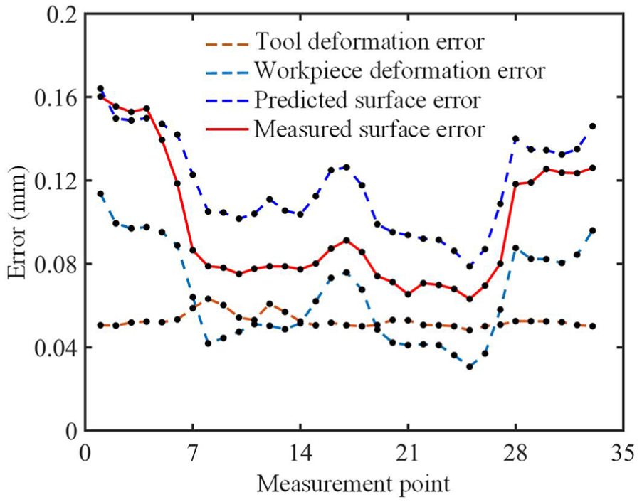
Predicted and measured surface errors at different measurement points.
The compensated surface error and its comparison with the uncompensated results are shown in Figure 10. The maximum deviation of the first surface, which is machined without any compensation, is 0.1602 mm. The maximum deviation of the second surface, which is machined according to the compensated code, is reduced to 0.0448 mm. These results illustrate that the surface error on the machined components was reduced by approximately 72% after applying the compensated machining code. This result indicates that the proposed compensation strategy can effectively improve the machining accuracy in the five-axis flank milling of thin-walled workpieces. In addition, the compensated profile is still affected by the curvatures of the surface. Because the test piece is an S-shape part, the accuracy of the machine is influenced by servo errors, which can be as high as several hundred micrometers. 19 As a result, the servo error can be accounted for in future studies to achieve a higher machining quality.
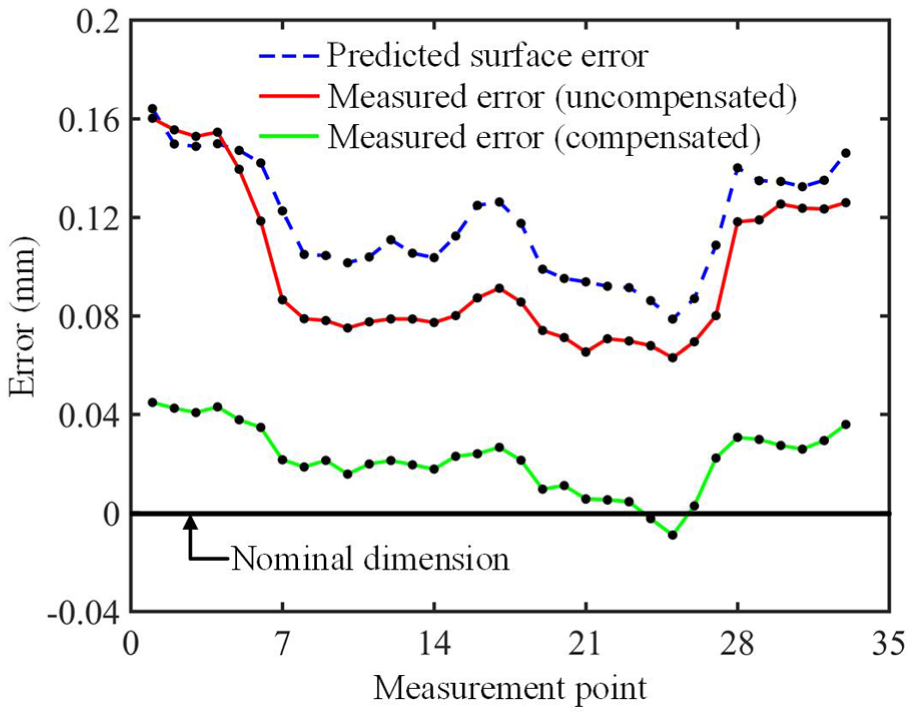
Comparison of the uncompensated and compensated results.
Conclusion
This article proposed an iterative compensation strategy to reduce the force-induced surface error during the five-axis flank milling of thin-walled workpieces. A novel CWE extraction method that considers changes in the process geometry caused by T/W deformations was introduced for the construction of a flexible cutting force model. The deformations of the tool and the workpiece are calculated using cantilever beam theory and finite element method (FEM), respectively. A machining code modification scheme was implemented on the basis of the convergence of error prediction and compensation routines. Machining experiments were performed to verify the effectiveness of the proposed compensation strategy. A comparison of the compensated and uncompensated results demonstrated that the application of the compensated machining code could significantly improve the machining accuracy of thin-walled workpieces with sculptured surfaces. The results of this work can offer knowledge regarding the off-line planning of tool paths in complex thin-walled parts machining and provide useful information on the selection of machining conditions for the processors prior to executing the machining operations.
Footnotes
Declaration of conflicting interests
The author(s) declared no potential conflicts of interest with respect to the research, authorship and/or publication of this article.
Funding
The author(s) disclosed receipt of the following financial support for the research, authorship, and/or publication of this article: This work was supported by the Major National S&T Program (2014ZX04014-031) and the National Natural Science Foundation of China (51675301).