
Abstract
The problem of springback is one of the most significant factors affecting the forming accuracy for aluminum 3D stretch-bending parts. In order to achieve high-efficiency and high-quality forming of such kind of structural components, the springback behaviors of the AA6082 aluminum profiles are investigated based on the flexible multi-points 3D stretch-bending process (3D FSB). Firstly, a finite element simulation model for the 3D FSB process was developed to analyze the forming procedure and the springback procedure. The forming experiments were carried out for the rectangle-section profile to verify the effectiveness of the simulation model. Secondly, the influence of tension on springback was studied, which include the pre-stretching and the post-stretching. Furthermore, the influences of the bending radius and bending sequence are revealed. The results show that: (1) The numerical model can be used to evaluate the effects of bending radius and process parameters on springback in the 3D FSB process effectively. (2) The pre-stretching has little effect on the horizontal springback reduction, but it plays a prominent role in reducing the springback in the vertical direction. (3) The increase of bending deformation in any direction will lead to an increase of springback in its direction and reduce the springback in the other direction. Besides, it reduces the relative error in both directions simultaneously. This research established a foundation to achieve the precise forming of the 3D stretch-bending parts with closed symmetrical cross-section.
Introduction
The aluminum profile stretch-bending process is one of the most widely used techniques for forming spatial structural parts in the manufacturing industry because of its high forming efficiency and excellent repeatability. 1 Generally, a solid die is designed for the manufacturing part with a specified shape in the conventional two-dimensional (2D) stretch-bending process. However, considering the improvement of aerodynamics, lightweight, and safety properties, modern vehicles’ structural design tends to be more complicated. More and more three-dimensional (3D) curved structural parts are designed and applied in the high-end equipment manufacturing industry. 2 It can provide a lighter, stiffer, and more space-saving skeleton structure than the 2D bending part. 3 Therefore, the study of how to achieve accurate stretch-bending for this kind of high-performance component always be a hot issue in the metal forming field.
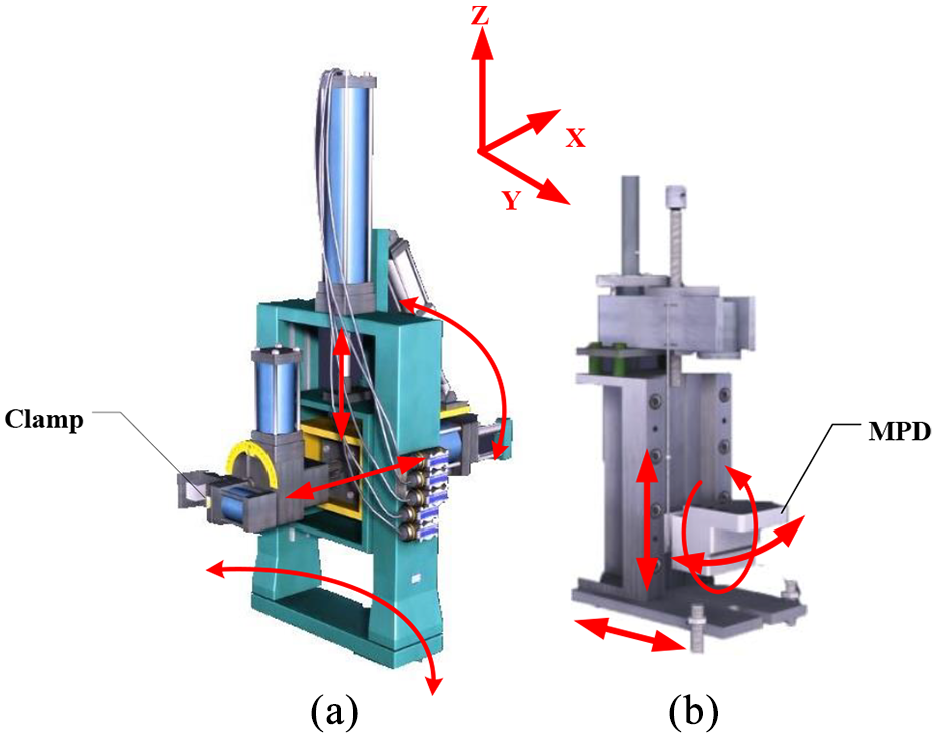
Due to the restriction of the solid die structure, the conventional stretch-bending process could not realize 3D stretch-bending for the aluminum profile with a complex cross-section. It needs to be improved for its low flexibility and reform its structure to achieve multi-dimensional stretch-bending. Since metal forming’s flexibility plays an essential role in customized mass and individualized production in the manufacturing industry, various flexible forming processes are proposed in recent years. 4 A typical one is the 3D free bending process, which can be used to produce complex tubes and profiles with asymmetrical cross-sections and continuously-varying radii.5–7 To realize the flexible forming of the conventional stretch-bending process, a new type of flexible multi-points 3D stretch-bending technology (3D FSB) has been developed. 8 As shown in Figure 1(a) and (b), based on the idea of multi-points forming technology, 9 the solid die in the traditional 2D stretch-bending process is replaced by the multi-point dies (MPD). The 3D forming was achieved by the superimposition of the horizontal bending and the vertical bending. The reconfigurable die surface makes the 3D FSB process efficient and flexible for 3D curved parts. Moreover, it is cost-effective for small lot production. The forming equipment is shown in Figure 1(c). Based on the 3D FSB process, a typical 3D curved structure part was precisely formed and employed in the Chinese CRH380 series high-speed train. 10 However, due to the coupling effects of multi-direction force and non-uniform deformation characteristics, it is found that the springback problem of the 3D stretch-bending parts is particularly prominent in the experiment. 11 Especially when forming a new part, it needs several times to adjust the envelope shape of the MPD to achieve precise forming, which caused such a waste of time, workforce, and material resources.
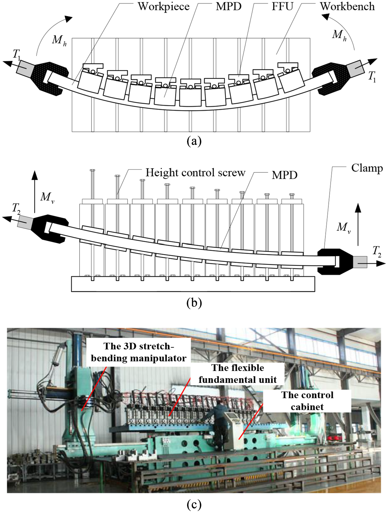
The forming principle of 3D FSB process: (a) the horizontal bending procedure, (b) the vertical bending procedure, and (c) the 3D FSB forming equipment.
The springback problem always is the main factor affecting the forming accuracy in the conventional stretch-bending process.12–14 The research on the springback mainly focuses on the two directions: (1) the prediction of springback, which is primarily based on the influence of the material constitutive and the bending parameters 15 ; (2) The method of springback control and compensation, that is, how to realize the precision forming.16,17 For 2D stretch-bending, Clausen et al. 18 proposed that the most critical factor affecting springback is the material’s strain hardening property and tensile force. The effects of tension, internal pressure, and friction on section distortion, springback, and net extension rate were systematically studied by Miller et al. 19 The parameters design strategy for the 2D stretch-bending process was obtained. Besides, a theoretical model to predict the 2D springback and section distortion by using the incremental strain theory was established. 20 Based on this, Corona 21 presented a formulation that can predict springback with arbitrary thin-wall section shape. The models used to calculate the springback and residual stress of 2D stretch-bending with U-section and T-section were introduced by El-Domiaty and Elsharkawy.22,23 Yu and Li 24 developed the springback prediction model for 2D stretch-bending of L-section aluminum profile. Ruixue et al. 25 divided the 2D stretch-bending into 12 cases and established the analytical model to predict the springback for rectangular and U-section profiles. Paulsen and Welo26,27 investigated the 2D deformation characteristic for rectangular single- and double-chamber AA6060 aluminum profiles with three different wall thicknesses, furthermore, a new, flexible rotary stretch bending machine, and analytical models to predict the springback are developed. 28 In addition, the 2D springback behaviors of Al-Li alloys profiles with Z-section and T-section were investigated by Liu et al. 29
The precision forming of the 2D stretch-bending parts is well evaluated in the previous research. However, there are relatively few systematic studies on the springback characteristics for 3D parts. With the increase of the forming dimension, the springback shows different characteristics in two different directions. The influence of the 3D bending parameters on springback becomes more complex and needs to be revealed urgently. Therefore, based on the 3D FSB process, in this paper, the springback characteristic of the 3D stretch-bending part is comprehensively and systematically studied by numerical simulation and experiment. The influence law of process parameters and geometric parameters on the 3D springback is discussed, which lays a foundation for accurate forming of the 3D parts with closed symmetrical cross-section.
Numerical simulation models
Based on the 3D FSB technology principle, the numerical simulation models for the forming procedure and the springback procedure were established using commercial finite element software ABAQUS. In order to compare the springback between the horizontal and the vertical direction, the typical symmetrical rectangle-section profile was adopted. The cross-section size of the profile is 40 mm × 40 mm, the thickness of the wall is 4 mm, and the length is 2.2 m. The shape of the target part is a symmetrical circular arc with a radius of 3.82 m and a central angle of 30° both in the horizontal and vertical directions. Considering that the forming process is a highly nonlinear quasi-static process, the dynamic explicit algorithm was used to simulate the forming procedure, while the static implicit algorithm was adopted in the analysis of the springback procedure.
Material model
The widely used AA6082 aluminum is applied in the analysis of the springback characteristics for 3D parts. Table 1 gives the parameters of this material, which are acquired by the uniaxial tensile test. According to the standard of GB/T 228.1-2010, the gauge size of a standard sample is 75.73 mm × 20 mm with a material thickness of 2 mm. The simulation model is established based on the following hypothesis: (1) the material acts agree the Von Mises yield criterion, and its plastic properties follow the Prandtl–Reuss flow rule; (2) The material performs isotropic in the strain-hardening model; (3) For small elastic deformation, the stress satisfies Hooke’s law. The AA6082 constitutive relationship can be express as:
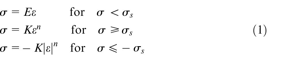
Where
The AA6082 mechanical properties.
FE simulation model
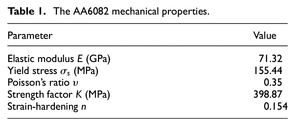
Figure 2 exhibits the developed simulation model. According to the forming equipment’s actual geometrical dimension, there are nine flexible fundamental units (FFU) employed in the forming process. Since the target part is symmetrical, a 1/2 geometrical model is used to improve calculation efficiency. Assume that only the workpiece is deformed in the forming process, the shell element S4R is adopted to mesh the workpiece, and the rigid element R3D4 is used to mesh the MPD. There are 1920 and 160 elements meshed on the workpiece and each MPD. The elements’ size is 18.33 mm × 5 mm and 6.25 mm × 5 mm for the workpiece and the MPD. The friction coefficient is 0.13 between profile and tools, which is tested by experiment.
Finite element simulation model for the 3D FSB process.
The 3D FSB forming is a result of multi-body motion and force coupling. In order to reduce the control complexity of the boundary conditions, the FFU and clamps are reasonably simplified. Under the displacement loading control mode, the clamp needs to have 4 degrees of freedom (DOF), as shown in Figure 3(a). They are the movement along the x-axis and z-axis, the rotation around the y-axis and the z-axis. The clamp’s motion trajectory determines the final geometric shape of the formed part. Therefore, as shown in Figure 2, the clamp is simplified as a reference point. It connects with the workpiece by the coupling connection unit. By controlling the reference point’s displacement, the workpiece can be stretched and bent as the actual clamp motion trajectory.
Structure diagram of the 3D stretch-bending manipulator and the FFU: (a) The 3D stretch-bending manipulator and (b) the flexible fundamental unit.
In the 3D FSB process, the MPD needs to move and rotate with the workpiece, as shown in Figure 3(b), which possesses 4 DOF. They are the movement and rotation on the y-axis and z-axis. Once the workpiece contacts the MPDs, it will be wrapped by the MPDs. Since the MPD could not rotate around the axis of the profile (x-axis), the torsion of the profile will be constrained. Therefore, the torsion problem will not occur during the forming process. The envelope shape of the MPDs in the horizontal direction is adjusted before the bending procedure, while the height control screw constrains the shape in the vertical direction. The axial connect unit is used to express the height control screw to simplify the FFU. Since the MPDs’ envelope is the equidistant curve to the characteristic line of the formed part, the adjustment position parameters of each FFU can be calculated according to the geometric shape of the target part.
Simulation results of 3D FSB process
Generally, the forming process for a 3D curved part can be divided into three steps. Firstly, the workpiece is stretched to the yield point
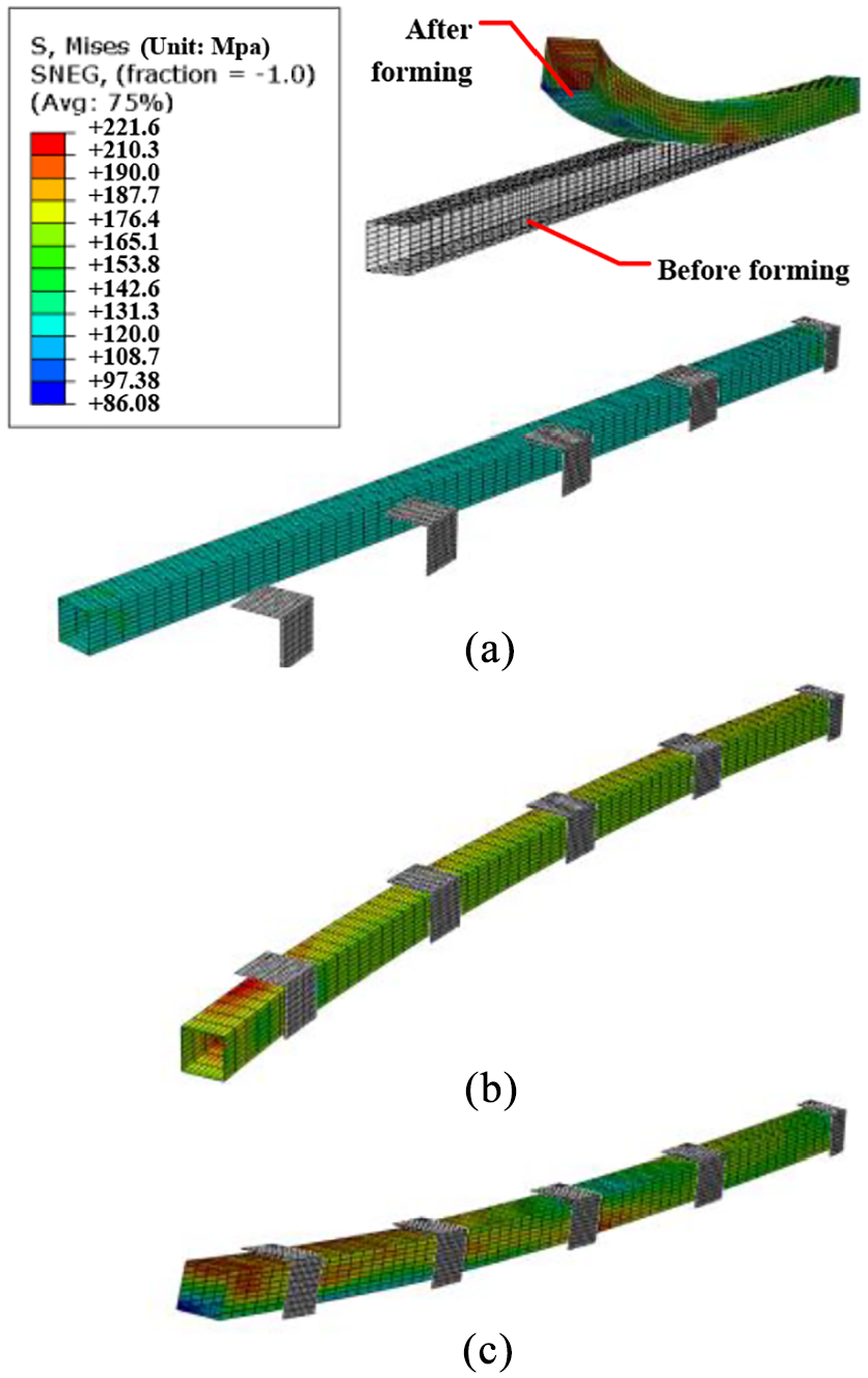
Simulation results of FSB forming process: (a) stress state after pre-stretching, (b) stress state after horizontal bending, and (c) stress state after vertical bending.
Springback prediction
Figure 5(a) shows the springback of a 3D stretch-bending part. The springback

Where
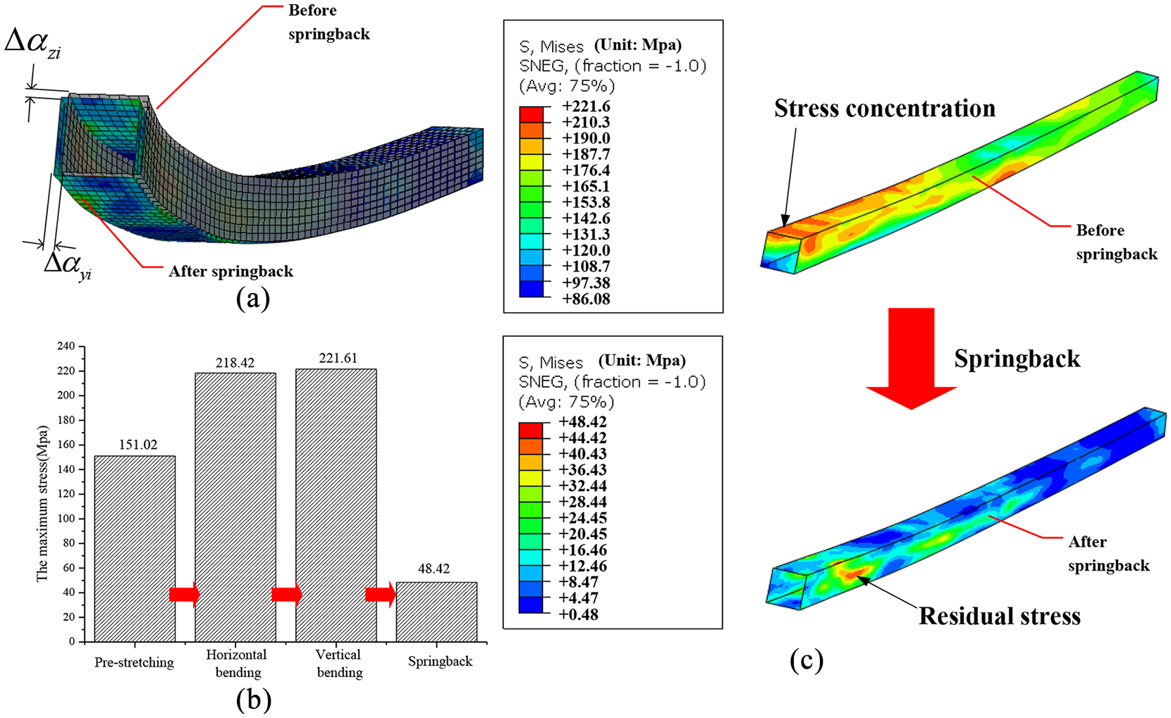
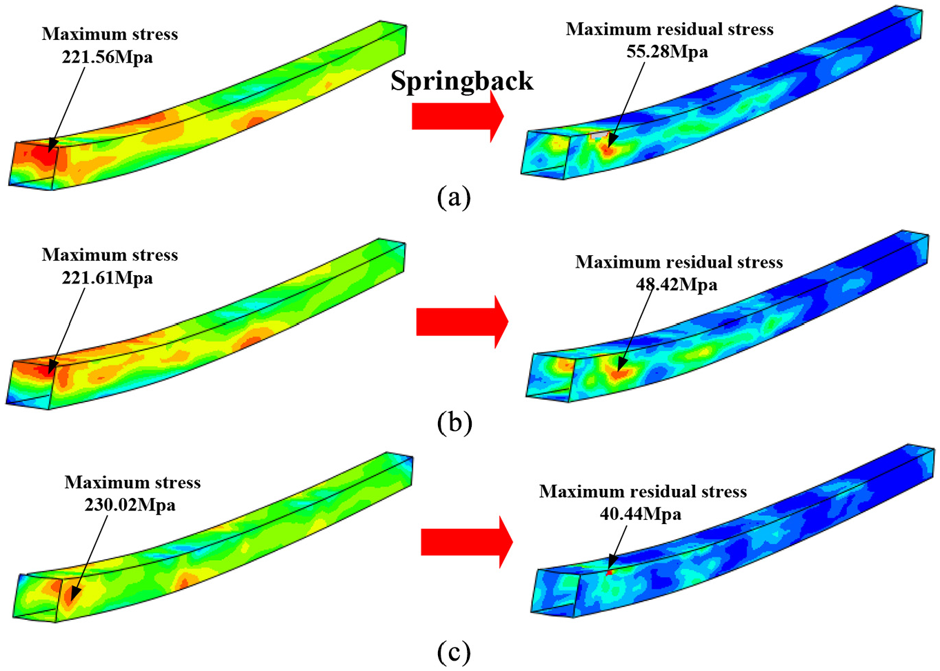
Springback prediction results: (a) the definition of springback, (b) the change of the maximum stress, and (c) the distribution of stress before and after springback.
Based on the simulation results, a springback prediction model is established using the ABAQUS/Standard module. In this model, all boundaries defined in the forming process are removed. Only one end of the workpiece is fixed constrained, which is the symmetrical center of the whole actual profile. The formed part’s stress state, mesh, and geometry shape are imported into the model using the predefined field function in ABAQUS. The profile that is constrained only at one end will move freely, resulting in springback deformation. Figure 5 shows the prediction results of springback. The shape deviations occurred both in these two directions. It can be seen that the vertical bending hardly changed the maximum stress in Figure 5(b), and most of the stress is released during the springback procedure. The maximum stress reduced to 48.42 MPa after springback. The springback at the edge of the bent part in the y- and z-axis is 4.04 and 2.48 mm. As shown in Figure 7(c), the stress concentration phenomenon appears after forming, the high-level stress is mainly concentrated on the upper and two side walls of the rectangular section. By comparing with the stress distribution after springback, the upper wall’s residual stress is better released than that on the two side walls.
Experimental verification
The 3D stretch-bending experiments for the rectangle-section profile are conducted to verify the effectiveness of the simulation. In the experiment, the critical process parameters, such as the material, the shape of the target part, the MPD’s adjustment parameters, and the clamps’ trajectories, are in agreement with the FE simulation model. The picture of the experimental part is compared with the simulated part, which is shown in Figure 6.
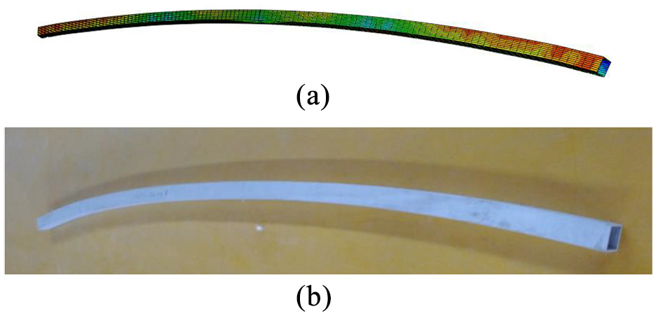
Comparison of the forming parts between simulation and experiment.
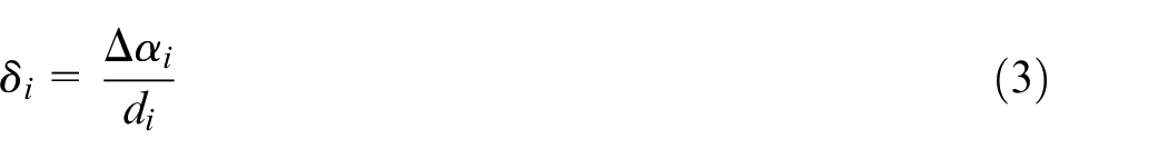
The geometric shape of the simulation result is consistent with that of the experiment. The dimensional error
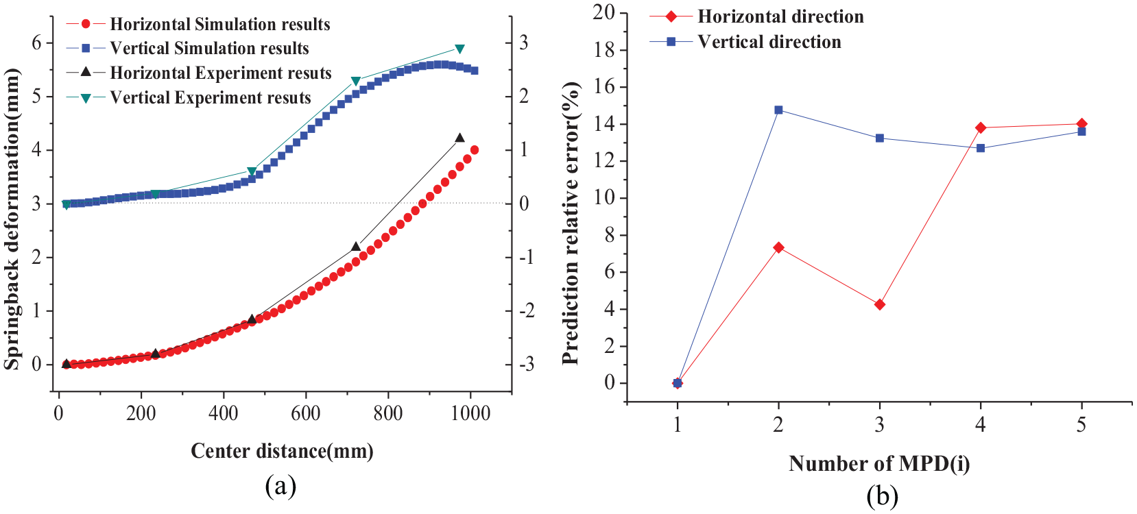
The springback simulation results: (a) comparison between simulation and experiment and (b) the ratio error of springback prediction.
By comparing the experimental data with the simulation data, it can be seen that the numerical model has successfully predicted the trend of springback. The maximum prediction error of springback is 0.52 and 0.36 mm in the horizontal and vertical direction, which occurred all at the outermost of the No.5 MPD. The relative error of predicted springback at each MPD is shown in Figure 7(b). The maximum relative error is 14.77%, while the average value is 11.71%. The numerical simulation results meet the springback prediction requirements for the 3D FSB process, which lays a foundation for the study of the following forming characteristics.
Springback characteristic for 3D stretch-bending parts
Effects of tension on springback
A load of axial tension plays an essential role in the stretch bending process. The axial tension is used to stretch the workpiece into the plastic state, which is an effective manner to reduce the springback. Also, it can help to prevent wrinkling caused by the compression. However, the excessive axial tensile force will lead to severe deformation of the cross-section. In this section, the effects of tension on springback in the 3D FSB process are studied. According to the different applied stages of tension, it can be divided into pre-stretching and post-stretching. They are discussed separately.
Effects of pre-stretching
Pre-stretching is the axial tension applied to the profile before the bending process. In order to acquire the influence law of pre-stretching on springback, the pre-stretching takes 0%, 20%, 40%, 60%, 80%, 100%, 120%, and 140%
Figure 8(a) and (b) demonstrate the pre-stretching effects on the horizontal and vertical springback, respectively. With the pre-stretching increase, the horizontal springback does not change obviously, while the vertical springback has a downward trend and varies significantly. Without the post-stretching, the vertical bending is performed on the curved surface after horizontal bending, which results in the uneven distribution of the stress on the formed part. After springback, its residual stress causes the non-monotonic increase of the vertical springback. Figure 8(c) shows the bilinear fitting curves of the maximum springback in the horizontal and vertical directions. Their trends are analyzed separately for below and above 100%
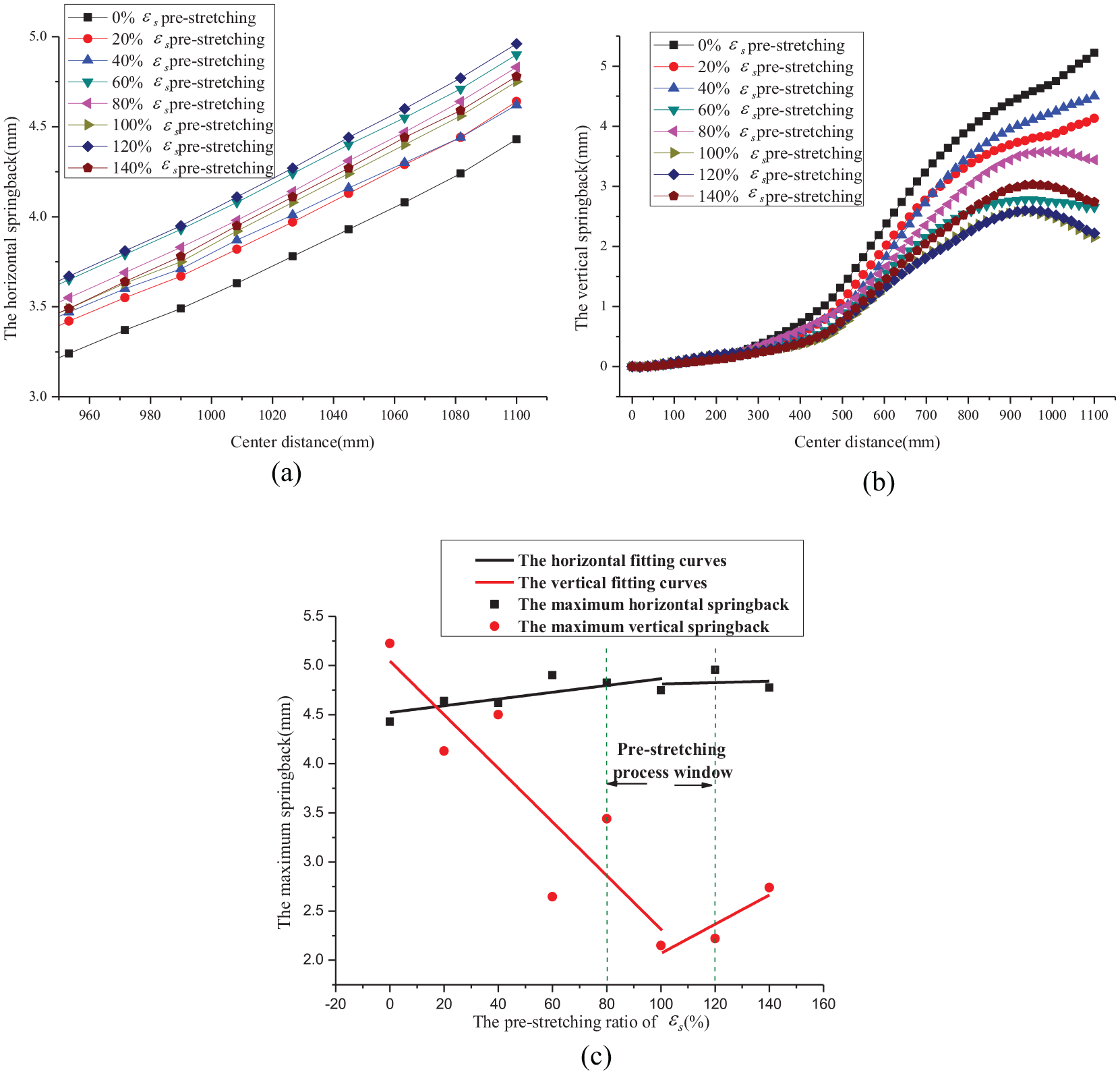
The effects of the pre-stretching on the springback: (a) the horizontal direction, (b) the vertical direction, and (c) the fitting curves of the maximum springback.
Effects of post-stretching
The post-stretching is the additional axial load after the bending procedure. In order to clarify its effect on springback, the 0%, 20%, 40%, 60%, 80%, and 100%
The simulation results are shown in Figure 9, in which Figure 9(a) and (b) are the horizontal and vertical springback with no pre-stretching. With the increase of the post-stretching value, there is almost no change for the horizontal springback, while the vertical springback is visibly declined, but it does not continue to decrease with the further increase of the post-stretching. The application of the post-stretching helps to retain the plastic deformation. However, according to the simulation results, when the post-stretching reaches 60%
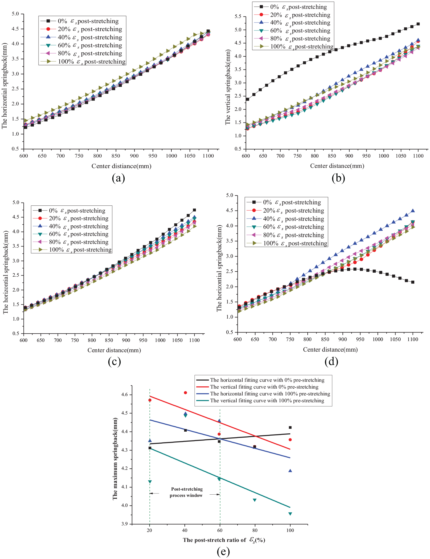
The effects of the post-stretching on the springback: (a) the horizontal direction (without pre-stretching), (b) the vertical direction (without pre-stretching), (c) the horizontal direction (100%
Figure 9(c) and (d) are the curves of the horizontal and vertical springback under the condition of 100%
In the condition with post-stretching, the linear fitting curves of the maximum springback with the increase of post-stretching ratio are shown in Figure 9(e). Except for the horizontal fitting curve with no pre-stretching, the other three curves show a downward trend. Whether pre-stretching is applied or not, the maximum horizontal springback does not show noticeable change, while the maximum vertical springback demonstrates apparent decline. Based on the above simulation results and analysis, we can conclude that the post-stretching tension application can effectively release the residual stress and reduce the springback. However, excessive post-stretching makes the section deformation serious. So in the actual production process, <40%
Effects of bending radius
Since the springback is closely related to the bending deformation, in this section, the tension parameters of 100%
The effect of horizontal bending radius
Under the same load condition, the simulation was conducted with the same vertical bending radius 3.82 m and different horizontal bending radius 3.82, 2.86, 2.29, and 1.91 m. The simulation results are shown in Figure 10, in which Rh is the horizontal bending radius and Rv is the vertical bending radius. As shown in Figure 10(a), the springback in the horizontal direction increases with the decrease of the horizontal bending radius, and the maximum horizontal springback rises from 4.5 to 6.34 mm. On the contrary, the vertical springback tends to decline, which is shown in Figure 10(b), and the maximum vertical springback deduces from 4.49 to 3.32 mm. The decrease of bending radius leads to the increase of horizontal deformation, so the increased plastic deformation accumulates more elastic deformation to be released in the horizontal direction, resulting in the raising of the horizontal springback. However, since the shape of the deformation in the vertical direction is the same, the plastic deformation in the horizontal direction strengthens the pre-stretching effect before the vertical bending, which makes the vertical forming is more sufficient, so the springback is reduced.
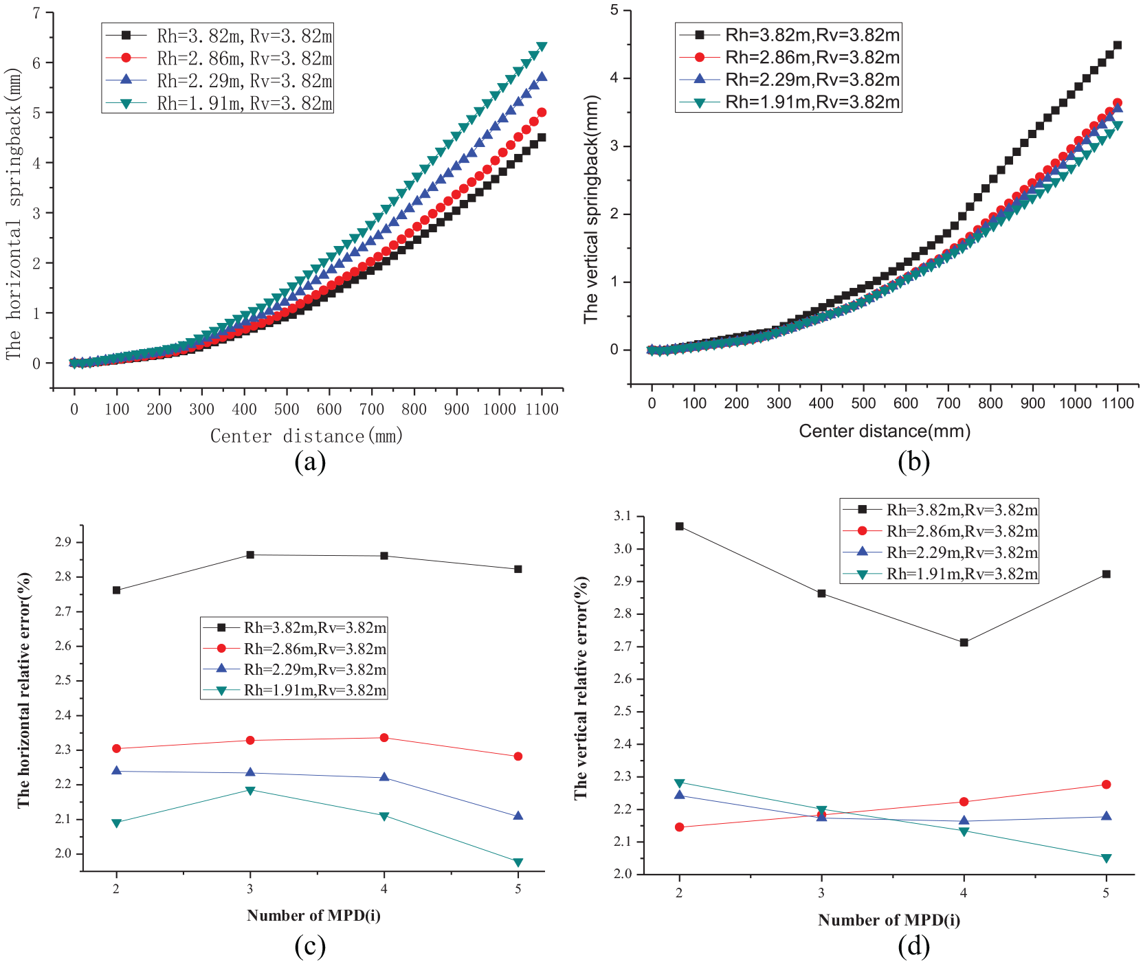
The effects of the horizontal bending radius Rh on the springback: (a) the horizontal springback with different Rh, (b) the vertical springback with different Rh, (c) the horizontal springback ratio error, and (d) the vertical direction springback ratio error.
According to equation (3), the relative error can be calculated at each MPD. So the influence of the deformation degree on the springback can be eliminated. It can be seen from Figure 10(c) that the horizontal relative error at different MPD only has slight variations at each horizontal bending radius, which shows that the deformation degree of each position on the profile is stable. In addition, although the horizontal springback is on the rise, the horizontal relative error shows a decreasing trend with the increase of the deformation. It reduced from 2.82% with Rh = 3.82 m to 1.98% with Rh = 1.91 m at the No. 5 MPD, which indicates that the increase of the horizontal bending plastic deformation suppresses the tendency of the springback to increase in the same proportion. As can be seen from Figure 10(d), the vertical relative error tends to decrease as the bending radius is reduced in the horizontal direction, it declined from 2.92% with Rh = 3.82 m to 2.05% with Rh = 1.91 m at the No. 5 MPD. Under each deformation condition, the vertical relative error at each MPD is the same.
The effect of the vertical bending radius
In this section, the horizontal bending radius was kept at 3.82 m, and the tensile process parameters unchanged. The test is conducted with the vertical bending radius is 3.82, 2.86, 2.29, and 1.91 m, respectively. The simulation results are shown in Figure 11. Since the vertical bending has a post-stretching effect on the horizontal forming, the more deformation occurred in the vertical direction, the more horizontal springback decreased. As shown in Figure 11(a), the maximum horizontal springback reduces from 4.50 to 2.49 mm. Although the target shape of the vertical direction changed considerably, the vertical springback does not vary significantly, and the maximum vertical springback only rises from 4.49 to 5.55 mm.
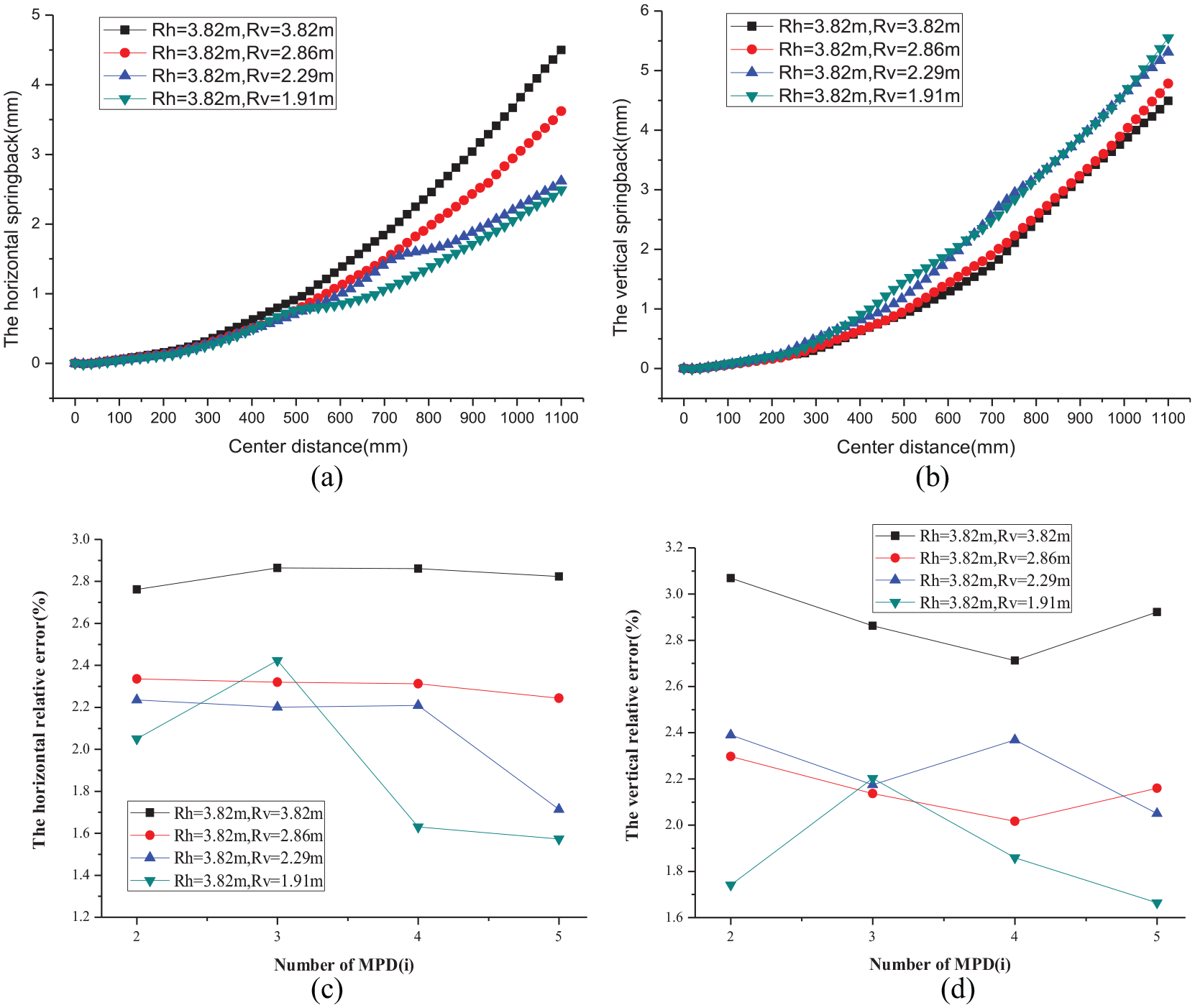
The effects of the vertical bending radius Rv on the springback: (a) the horizontal springback with different Rv, (b) the vertical springback with different Rv, (c) the horizontal relative error, and (d) the vertical relative error.
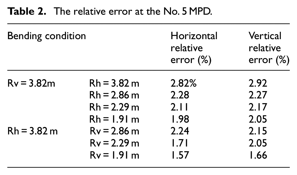
As shown in Figure 11(c) and (d), the relative error in the horizontal and vertical directions decreases with the increase of the vertical deformation. The horizontal and vertical relative error of the workpiece is stable under each deformation condition. Besides, take the relative error at the No. 5 MPD as an example, the relative error in the horizontal and vertical directions are similar in any forming conditions. Its values are related to the deformation degree of the whole workpiece, which is illustrated in Table 2.
The relative error at the No. 5 MPD.
Discussion
In order to achieve the high-quality forming of the 3D stretch-bending parts, the parameters design strategy of the 3D FSB process should be considered from two aspects: the tensile parameters and the geometric parameters. In terms of tensile parameters, the method of pre-stretching and post-stretching should be used together, the process windows for pre-stretching and post-stretching are shown in Figures 8(c) and 9(e). The pre-stretching range from 80% to 120%
The effect of the tension on the distribution of stress: (a) case 1: no pre-stretching and no post-stretching, (b) case 2: 100%
For the geometric parameters, the effect of the bending radius on the max horizontal and vertical springback is shown in Figure 13. It can be concluded that: if the deformation is aggravated in any one direction, the springback in this direction will be increased, while the springback in the other direction will be reduced. Besides, if we convert the springback into the rate-related parameters, we can see that the relative error is always <3%. The relative error does not increase with the rise of the center distance. Its value is maintained as a relatively stable parameter at each MPD. The increase of bending deformation in any one direction will reduce the relative error both in the horizontal and vertical directions at the same time.
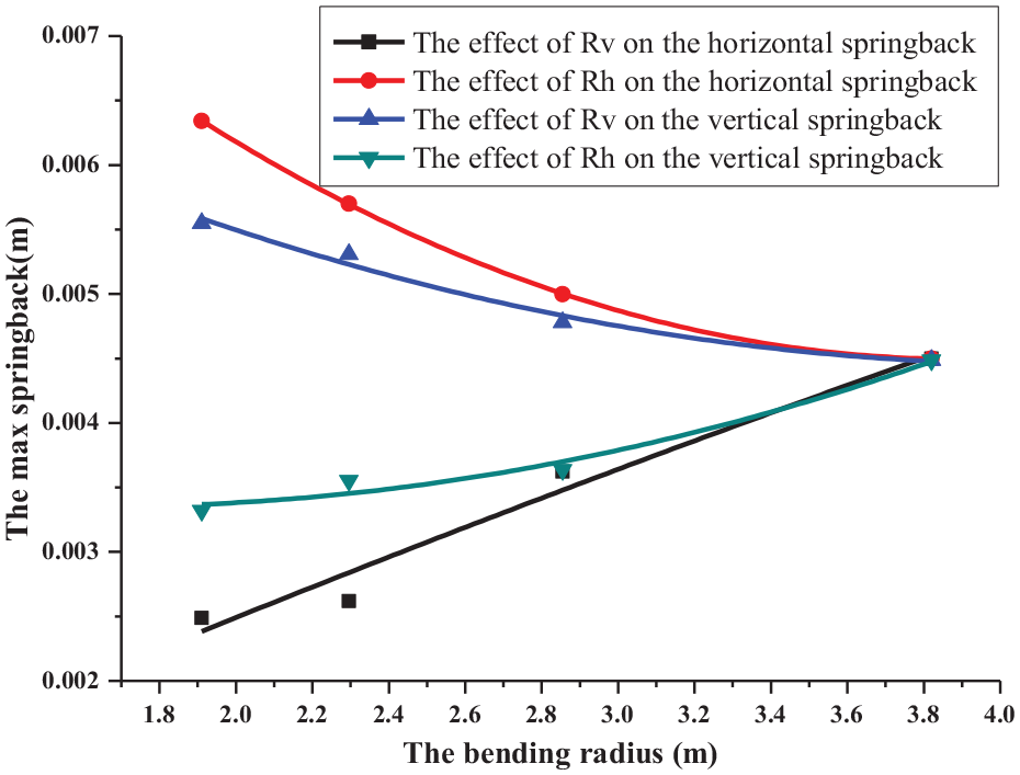
The effects of the bending radius.
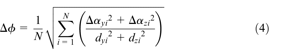
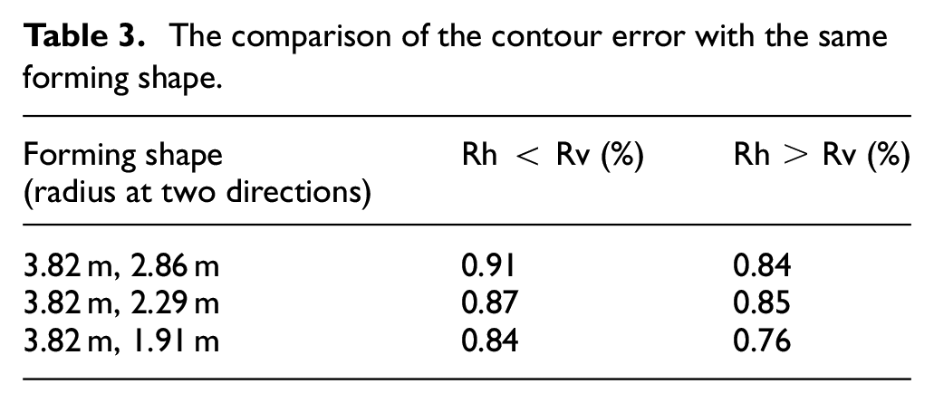
Since the workpiece is a center symmetry profile with a rectangular cross-section, the final shape is the same for the forming condition at Case 1: Rh = 3.82 m, Rv = 1.91 m, and Case 2: Rh = 1.91 m, Rv = 3.82 m. The stress distribution of these two cases is shown in Figure 14. The simulation results are displayed in mirror symmetry for comparison. Due to the different bending sequences, the formed parts show different springback under the same tensile parameters. The maximum stress in Case 1 is greater than that in Case 2, both before and after springback. Since the residual stress of Case 1 is not released well, the contour error of the formed part is less than that of Case 2. There is no obvious forming defect occurred in Case 1 and Case 2. According to equation (4), the contour error is calculated in Table 3. Without considering the section deformation, the contour error of the Rh < Rv group is always larger than that of the Rh > Rv group. Therefore, if the cross-section of the formed workpiece is symmetrical, it can be concluded that the bending sequence should be arranged as small deformation in the horizontal direction and the large deformation in the vertical direction to further reduce the springback.
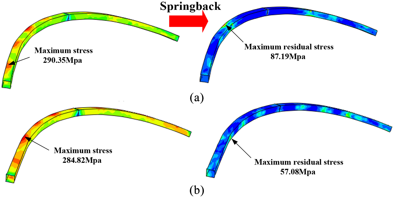
The effect of the bending sequence on the distribution of stress: (a) case 1: horizontal 3.82 m, vertical 1.91 m and (b) case 2: horizontal 1.91 m, vertical 3.82 m.
The comparison of the contour error with the same forming shape.
Conclusion
The 3D curved structural parts are more and more designed and used in the high-end equipment manufacturing industry. In this paper, extensive numerical simulations for the 3D FSB process have been performed to determine the springback characteristics.
According to the principle of the 3D FSB technology, the numerical simulation models were established. The simulation results of the rectangle-section profile are in good agreement with the experimental results. The prediction error of springback is <0.52 mm in the horizontal direction and 0.36 mm in the vertical direction. The maximum predicted relative error is 14.77%, while the average value is 11.71%.
The pre-stretching has little effect on the horizontal springback reduction, but it plays a prominent role in reducing the springback in the vertical direction. Besides, the application of the post-stretching can effectively release the residual stress and reduce the springback. However, excessive post-stretching makes the section deform severely. In the actual production process, 100%
For the effect of bending radius, the increase of bending deformation in any direction will lead to an increase of springback in its direction and reduce the springback in the other direction. Moreover, it will reduce the relative error both in these two directions simultaneously. The relative error is maintained as a relatively stable parameter which is <3% at each MPD. The bending sequence also affects the forming precision. The large deformation should be arranged in the vertical direction further to reduce the springback in the 3D FSB process.
Footnotes
Declaration of conflicting interests
The author(s) declared no potential conflicts of interest with respect to the research, authorship, and/or publication of this article.
Funding
The author(s) disclosed receipt of the following financial support for the research, authorship, and/or publication of this article: This work was supported by the National Natural Science Foundation of China (No.51805045) and Scientific and Technological Developing Scheme of Ji Lin Province (Nos. 2019 0302100GX, 20200401115GX).
Availability of data and materials
The data during the current study are available from the corresponding author on reasonable request.