
Abstract
Incremental sheet forming is a cost-effective process for rapid manufacturing of sheet metal products. However, incremental sheet forming also has some limitations such as severe sheet thinning and long processing time. These limitations hamper the forming part quality and production efficiency, thus restricting the incremental sheet forming application in industrial practice. To overcome the problem of sheet thinning, a variety of processes, such as multi-step incremental sheet forming, have been proposed to improve the material flow and thickness distribution. In this work, a new process has been developed by introducing multi-point forming as preforming step before conducting incremental sheet forming processing. Employing an established hybrid sheet forming system and the corresponding thickness prediction model, the preform shape can be optimized by employing a two-step optimization approach to improve the sheet thickness distribution. In total, two case study examples, including a hemisphere part and an aerospace cowling part, are fabricated using the developed hybrid flexible process in this study. The experimental results show that the hybrid flexible forming process with the optimal preform design could achieve sheet parts with more uniform thickness distribution and reduced forming time.
Keywords
Introduction
When producing sheet metal parts with a relatively small lot size, conventional sheet forming technologies, such as stamping, have many limitations due to the long lead time and costly tool set manufacturing. Alternatively, the flexible sheet forming approach becomes a better solution for rapid manufacturing of small-batched and customized products. With the advantage of reduced lead time and tool costs, flexible sheet forming processes show a great potential in rapid prototyping and small-batch manufacturing. This method is especially useful in the manufacturing applications of aerospace, biomedical and automotive prototyping development. Concerning the technologies of flexible forming, incremental sheet forming (ISF), multi-point forming (MPF) and asymmetric spinning are three typical flexible sheet forming processes.
In the MPF process, matrices of tool pins are employed as an alternative to traditional rigid die. 1 By adjusting the height of individual pins, three-dimensional (3D) freeform surface can be obtained. The idea of forming sheet metal parts using discrete pins was first proposed by Nakajima 2 in the 1970s. However, challenges come from surface defects such as dimples caused by discontinuous contact between the sheet and the punch. 3 Li and colleagues4–6 improved the MPF process by developing homogeneous deformation forming path, blank-holding strategies and improving the cushion conditions. Hardt et al. 7 introduced the closed-loop shape control into the MPF system. However, due to the use of the discrete pins as the forming die, sheet geometries that can be produced using this approach are still limited. Asymmetric spinning was developed based on the traditional spinning technology. 8 In this process, rollers are employed to replace the traditional full mandrel. In addition, synchronized movements are maintained between the roller and mandrel to generate asymmetric geometry. Xia et al. 9 produced a comprehensive review of the asymmetric spinning processes. However, achieving geometries with strong asymmetric features is still a challenging task in asymmetric spinning.
ISF is another flexible sheet forming approach. In the ISF process, a stylus-type forming tool moving along a predefined 3D trajectory locally deforms the clamped blank peripherally and gradually achieves the designed geometry. 10 Freeform 3D shapes can be gradually obtained with the predefined tool movement. Since the development of ISF concept in 1960s, 11 efforts have been made to explore various variations of the ISF process. Matsubara 12 proposed a two-point incremental forming (TPIF) process, in which the blank was deformed under the support of a male die. Meier et al. 13 developed a double-sided incremental forming (DSIF) process using two forming tools at both sides of the sheet. Malhotra et al. 14 proposed an accumulative double-sided incremental forming (ADSIF) process with improved thickness distribution. Araghi et al. 15 presented a hybrid sheet forming process combining the stretching and ISF processes together. In these processes, complex sheet parts can be formed by applying geometry specified tool paths.
Although ISF possesses high process flexibility, its industrial application is still limited due to low geometrical accuracy, long processing time and severe sheet thinning. Adams and Jeswiet 16 recently summarized some guidelines and design rules for multi-step incremental forming processes. To improve the geometrical accuracy, Micari et al. 17 investigated the key ISF parameters that affect the geometrical accuracy. Allwood et al. 18 employed stereovision cameras to obtain geometrical feedback and implement online compensation on the predesigned tool path. Asghar et al. 19 developed an analytical model to compensate for the sheet deflection and tool deflection. Al-Ghamdi and Hussain 20 focused on the pillow tendency defect in the middle of the parts, and the experimental results show that lower hardening exponent had a positive effect on control pillowing. Malhotra et al. 21 developed a squeezing tool path strategy in DSIF to improve the geometrical accuracy. These approaches could effectively enhance the ISF geometrical accuracy. Another ISF challenge comes from severe sheet thinning after forming. To predict the thickness distribution, Bambach 22 developed a geometrical model to calculate the sheet thickness by assuming that surface points always move along the normal direction of the surface. To improve the thickness distribution, Duflou et al. 23 developed the multi-pass forming strategy. Manco et al. 24 adopted four multi-step strategies to investigate the influence of forming path on thickness distribution. Zhang et al. 25 designed a number of intermediate shapes in multi-step ISF by employing the hydro-bulging forming concept. Liu et al. 26 carried out further work in designing the intermediate shapes using a systematic methodology. However, one drawback of multi-step strategy is the increased processing time. Different from the multi-step strategy, DSIF 21 and ADSIF 14 strategies may also be used to improve the sheet thickness by controlling the amount of sheet squeezing under forming load. In addition, a hybrid forming process by combining the stretching process and ISF process together was proposed by Araghi et al. 15 This process could also improve the thickness distribution. However, in this hybrid process, a specified supporting die is required. In the ISF process, as the sheet is peripherally clamped, no material could flow into the region of the shape formed; therefore, sheet thinning becomes unavoidable.
In this work, an improved flexible forming process combining MPF as preform process and ISF as finish forming process has been developed. To determine the preform shape in the MPF process, a two-step optimization approach has been developed based on a thickness prediction model. Key parameters, such as the drawing depth and the preform shape, are determined using the developed optimization approach. In total, two case study problems, including forming a hemisphere part and an aerospace cowling, are investigated to validate the developed hybrid flexible process. The validation results suggest that the new hybrid flexible forming process could achieve sheet parts of greater depth with more uniform thickness distribution. Finally, discussions and conclusions are made based on the results of numerical and experimental investigation.
Methodology
The hybrid flexible forming approach
By combining the MPF and ISF, the concept of the hybrid flexible forming process is illustrated in Figure 1. In the preforming step, the MPF process is implemented to produce a preform, which allows materials at the blanking area to flow into the deformation region. While the baseplate is stationary, the pins on the baseplate are adjusted to the designed height to represent the preform shape. Then, the blank, clamped by the blank holder, travels down against the pin die, and a preform shape is obtained. To control the dimples and to reduce the other effects caused by the discontinued pins, rubber cushion is used in the process between the pin die and the sheet. After preforming, an ISF process is then performed to finalize the sheet metal part. In the ISF process, the versatile tool moves along the tool path and gradually deforms the sheet metal into the desired geometry. To avoid geometrical errors, the inflow of material is not allowed in the ISF process. Particularly, in the ISF process, the tool deforms the sheet from the concave side of the preform. In this way, the sheet can be further deformed by the subsequent ISF process, and therefore, the dimples left by the MPF process could be removed. This hybrid process has many benefits, including the following:
Avoidance of extreme sheet thinning. The MPF process and the ISF process are complementary in the thickness distribution. In the MPF step, inflow of material is allowed as shown in Figure 1. With the material supplement, the average thickness is improved compared with conventional ISF. Deformation mode and main thinning area in the MPF step are also different from the ISF step, as shown in the part cross section in Figure 1. In the MPF step, thinning occurs at the center region of the part. In the ISF step, thinning occurs at the boundary due to the large forming angle. With the different thinning regions, a comparatively even thickness distribution can be achieved.
Higher process flexibility. As the multi-point pin die is reconfigurable, the flexibility of this hybrid process can be maintained without using expensive dies.
Higher formability. Although the formability at preform step is similar to that in the conventional stamping, the formability can be further improved in the final ISF process.
Improved efficiency. Unlike the conventional multi-pass ISF process, with the involvement of MPF, only a single-step ISF operation is required to form the desired part. In this way, the process efficiency is improved comparing with the conventional multi-pass ISF.
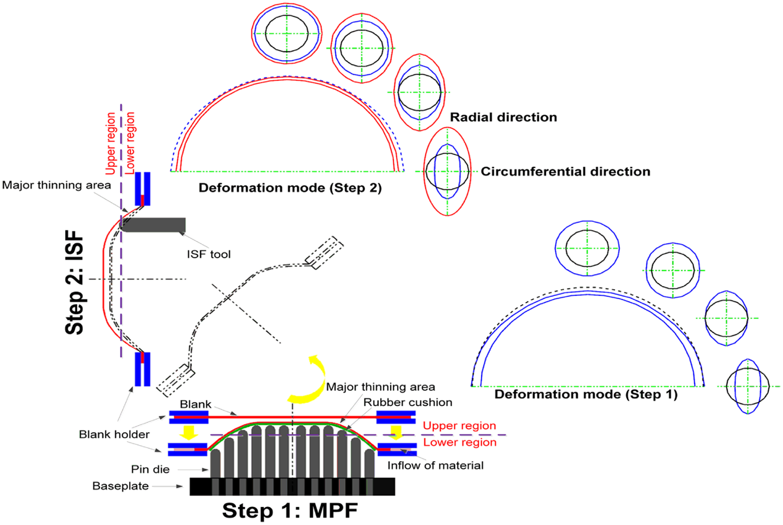
The new hybrid ISF process: step 1: multi-point forming process and step 2: incremental sheet forming process.
To realize the proposed hybrid flexible forming process, a hybrid flexible forming system has been developed as shown in Figure 2. This forming system consists of a hydraulic preforming module and a robotic ISF module. In the preforming module, the pins are fixed onto the stationary baseplate, and the heights of pins are adjusted by rotating the pin through its thread. The blank holder is mounted on the MPF frame during the preforming, as shown in Figure 2(a). The hydraulic cylinders are employed to drive the MPF frame to move toward or away from the pin die. When the MPF step is completed, the preformed part together with the blank holder is detached from the MPF frame, rotated by 90° to the vertical position and fixed onto the ISF frame, as shown in Figure 2(b). The ISF process is implemented, and the sheet metal is further deformed by a six-axis industrial robot.
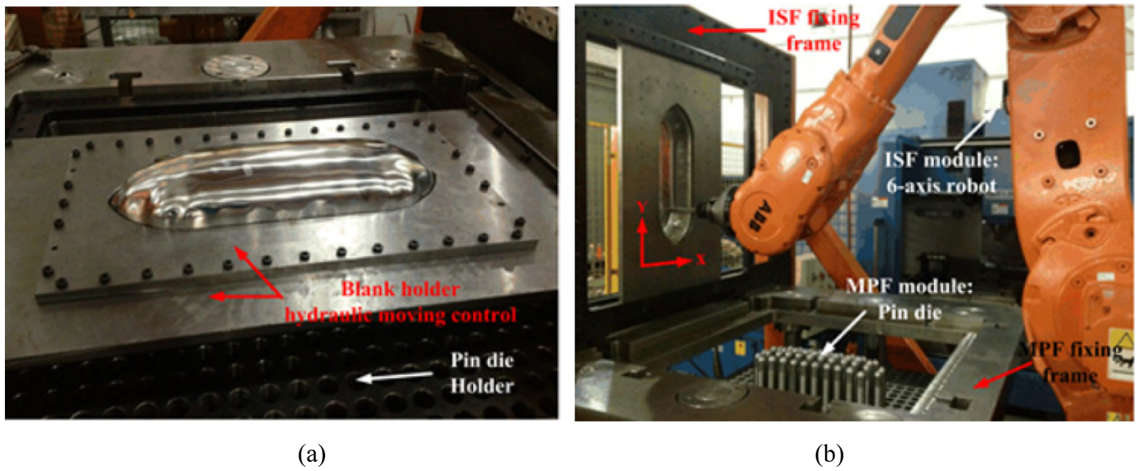
Hybrid ISF rig: (a) hydraulic preforming module and (b) robotic ISF module.
Although this new flexible and hybrid process has many advantages, the implementation of this hybrid process still faces challenges. In the hybrid process, the preform shape plays a key role in producing uniform thickness distribution. To obtain an optimized preform, design and shape optimization procedures are employed through numerical process modeling for the prediction of final thickness distribution of the formed part.
Numerical prediction of thickness distribution
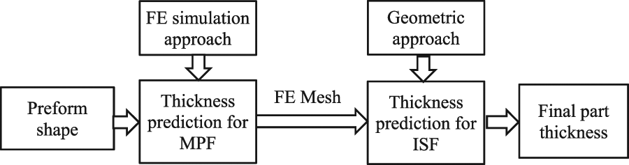
Before implementation of preform shape optimization, a thickness distribution model is developed in this work. This thickness prediction model includes two steps as shown in Figure 3: the MPF thickness prediction step and the ISF thickness prediction step. For the MPF step, the thickness distribution is predicted using the finite element (FE) approach. For the ISF step, although FE approach could provide an accurate thickness prediction result, 27 the long simulation time is a challenging issue in the shape optimization procedure because many thousand iterations are required. In this work, the thickness distribution is predicted using a more efficient geometrical approach. 28
Material flow and sheet thickness prediction model.
In this work, ABAQUS explicit code is employed to simulate the preforming process as shown in Figure 4(a). In the FE model, to ensure the simulation efficiency and accuracy, for the blank, shell elements S4R are used with five integration points along the thickness direction. The side length of each element is 1 mm. For the rubber cushion, Ogden model (N = 3) is adopted to represent the constitutive relation. Detailed parameters for the rubber can be found in Liu et al.’s 6 work. In the material model, von Mises yield criterion and isotropic hardening are employed. For the ISF step, as the numerical simulation is less efficient, a geometrical approach has been employed. In the approach, as the sheet is under stretching condition, the material is assumed to move along the sheet normal direction. 24 In this way, the nodal position can be updated, and the thickness can be calculated based on the updated position of nodal points. Using this approach, the final thickness distribution of the part can be obtained in a relatively short time. To enable the proposed sheet thickness prediction model to run automatically, an in-house developed program is employed to integrate the ABAQUS simulation, extract the simulation results and calculate and output the final sheet thickness.
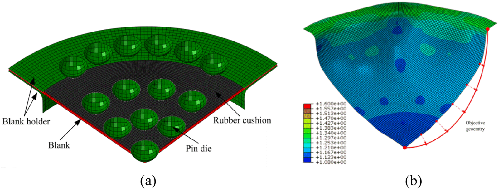
Two-step sheet thickness prediction: (a) preforming ABAQUS explicit simulation and (b) final forming geometrical prediction approach.
Determination of preform height and shape
In the hybrid forming method, the MPF drawing depth (preform height) and the preform shape are the two main parameters that affect the final thickness distribution. The drawing depth determined the amount of sheet flowing into the cavity and the preform shape determined the uniformity of thickness distribution. In the optimization, as there are many parameters, the optimization of drawing depth and preform shape are considered separately, and a two-step optimization process is employed: (1) determination of drawing depth and (2) optimization of preform shape.
Concerning the determination of drawing depth, with the increasing drawing depth, more materials will be drawn into the forming area. This can result in higher average thickness. However, if the drawing depth is too large, defects such as fracture, severe wrinkling and ISF rigid-body motion may occur in the hybrid forming process. An appropriate drawing depth is required to maximize the uniform thickness distribution but avoid sheet failure. Concerning the determination of preform shape, as the geometry of the preform is described by a series of NURB curves with control points, the preform shape is optimized by varying the position of control points. This kind of optimization model may involve in considerable number of optimization variables. In this work, an uncoupled two-step optimization strategy is employed. In the first step, the optimization objective is to find the maximum MPF drawing depth without forming defects, such as severe wrinkling. In the second step, the preform shape is optimized based on the optimized drawing depth with the conventional gradient-based search method. 29
The detailed optimization procedure is described by Figure 5. Started from an initial preform shape, preform process is simulated, and the drawing depth is optimized by gradually increasing it. This process will be stopped when reaching the limit to avoid possible stepped feature in ISF process, wrinkles unable to be removed and fracture. With the optimized drawing depth, thickness distribution can be optimized using the geometrical approach. The shape optimization can be implemented by modifying the control points. The above-described procedure is achieved by an in-house developed optimization code.
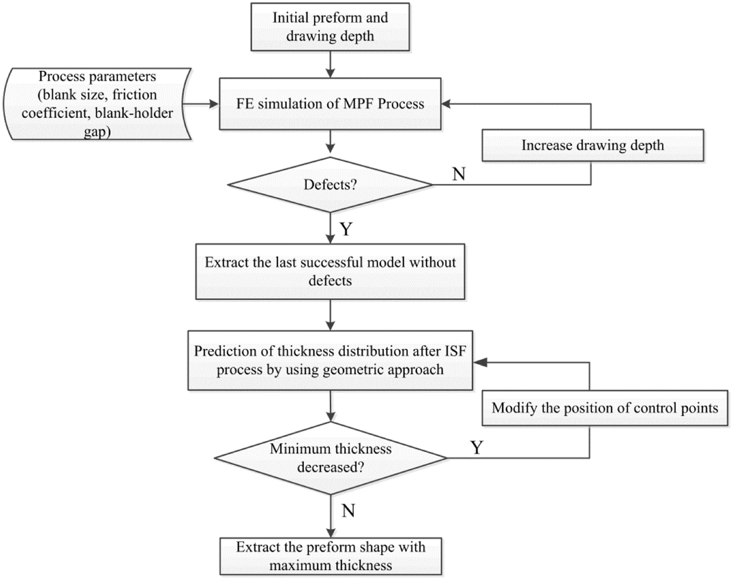
Two-step optimization procedure.
Case study
To validate the developed approach on preform shape design, two case studies, including forming a hemisphere part and an aerospace cowling part, are implemented. Using these two case studies, the accuracy of the thickness prediction model and the effect of the preform shape optimization methods are evaluated. In both cases, aluminum alloy 2A12-O with initial sheet thickness of 1.2 mm is employed in this work. In the material model, Young’s modules of 55 GPa and Poisson’s ratio of 0.35 have been used. For the plastic model, the flow stress provided by discrete points from tensile test has been shown in Figure 6. For the annealed AA 2A12-O, the material is considered as isotropic. Concerning the friction coefficient, Figueiredo et al. 32 measured the friction coefficient as 0.1–0.15 from draw bead test for aluminum sheet AA 1100. Sanchez et al. 30 and Wei et al. 31 also measured friction coefficient for sheet metal forming, in which the value is around 0.15. According to these studies, the friction coefficient of 0.15 has been employed in the simulations in this work.
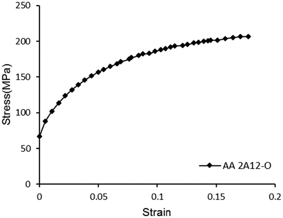
2A12-O flow stress–strain diagram.
Case study 1: hemisphere
In the first case, a commonly used hemisphere part, shown in Figure 7, is fabricated to validate the developed hybrid forming process. The diameter of the hemisphere is 150 mm. Concerning the blank size, if it is too small, it may not provide enough material inflow in the forming process. On the contrary, if it is too large, wrinkling and other defects may occur during the process. In this work, both blank diameters of 200 and 250 mm have been tried, and the diameter of 200 mm has been employed due to better material inflow without obvious wrinkling. In the ISF process, a forming tool with radius of 5 mm is employed. Helical tool path with constant scallop height of 0.005 mm is employed in order to achieve uniform surface roughness at different forming angles. In order to validate the developed sheet thickness prediction model, a series of verification has been implemented. The developed thickness prediction model is compared with the experiment result, and the different optimization steps are individually compared. Finally, the optimized result is then compared with the conventional multi-step ISF process.
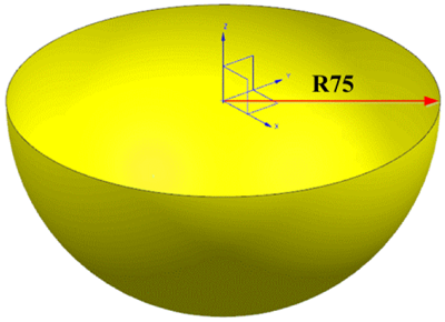
The designed hemisphere (mm).
Preform shape optimization
Due to the axisymmetric feature of the geometry, a two-dimensional (2D) spline curve controlled by five points P1–P5 is employed to describe the cross section, as shown in Figure 9(a). Concerning the initial preform shape design, the initial drawing depth is assigned to be 35 mm, and the maximum sheet thinning is 6.7% according to the prediction. In the optimization, the drawing depth is increased gradually by moving upward points with an interval of 5 mm as illustrated in Figure 8. When the drawing depth reaches 50 mm, the maximum sheet thinning is about 12.58%. However, this drawing depth cannot be further increased when the drawing depth reaches 55 mm. This is because the stepped feature can be found in the following ISF process, which is caused by the rigid-body motion. 33 In this way, the forming depth of 50 mm is obtained in the preforming step.
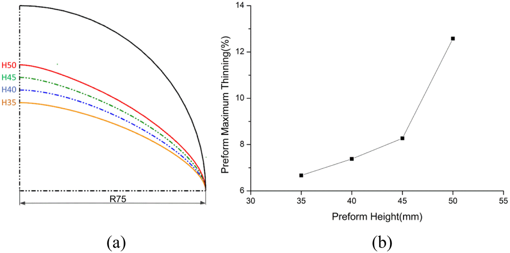
Preform height optimization: (a) preform height optimization (mm) and (b) maximum sheet thinning in preform height optimization.
To achieve a higher and more uniform thickness distribution, shape optimization of the preform has also been implemented. In the shape optimization, control points P1, P2, P4 and P5 are fixed to ensure the C0 and C1 continuity at two ends, as shown in Figure 9(a). Only the control point P3 can be varied and position of P3 is modified along the normal direction of spline to obtain the best preform shape. As shown in Figure 10, when the preform shape varies from C1 to C3, the final thickness distribution was improved. However, further preform optimization to C4 failed to improve the thickness distribution. Thus, the preform shape C3 is employed in this work. The thickness distributions using preform C1 and C3 are compared in Figure 9(c) and (d).
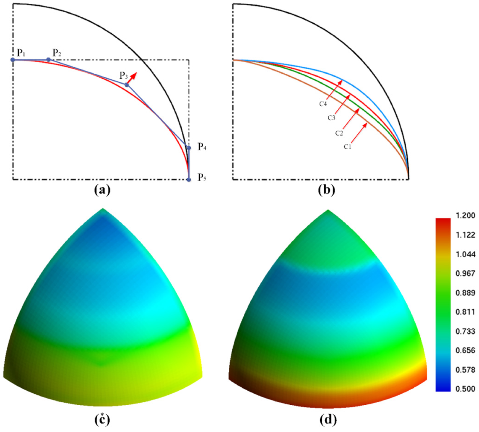
Preform shape optimization: (a) shape control method, (b) optimization process: c1–c4, (c) part thickness distribution under C1 and (d) part thickness distribution under C4.
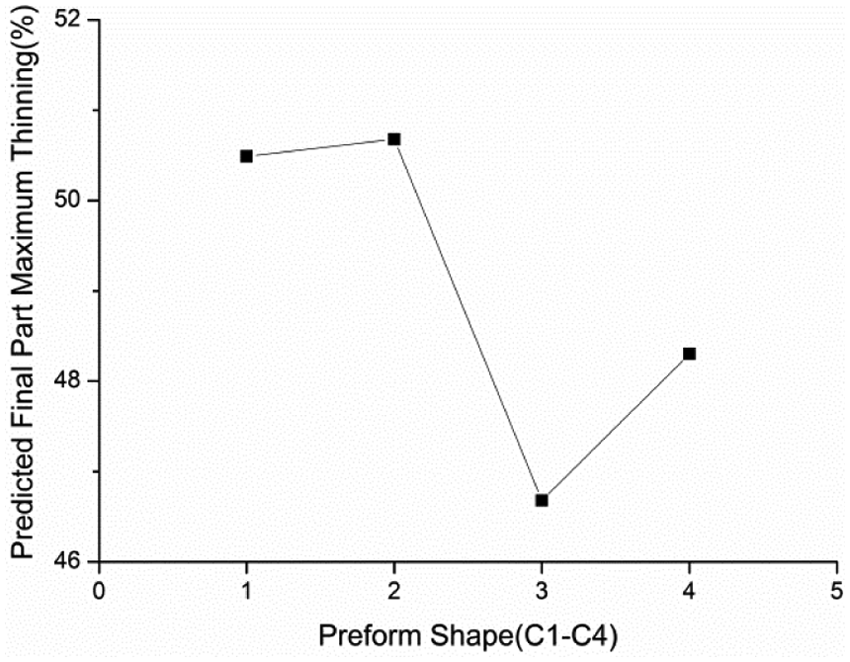
Predicted final part maximum sheet thinning during preform shape optimization.
Using the optimized drawing depth and preform shape, physical experiments are implemented using the developed forming system. As shown in Figure 11, the hemisphere part could be successfully obtained. In the MPF step as shown in Figure 11(a), dimples can be observed on the part surface. These dimples are caused by the pin die as rubber cushion does not provide enough support in the MPF process. However, these defects are removed in the ISF process, and a smooth surface is obtained, as shown in Figure 11(b).
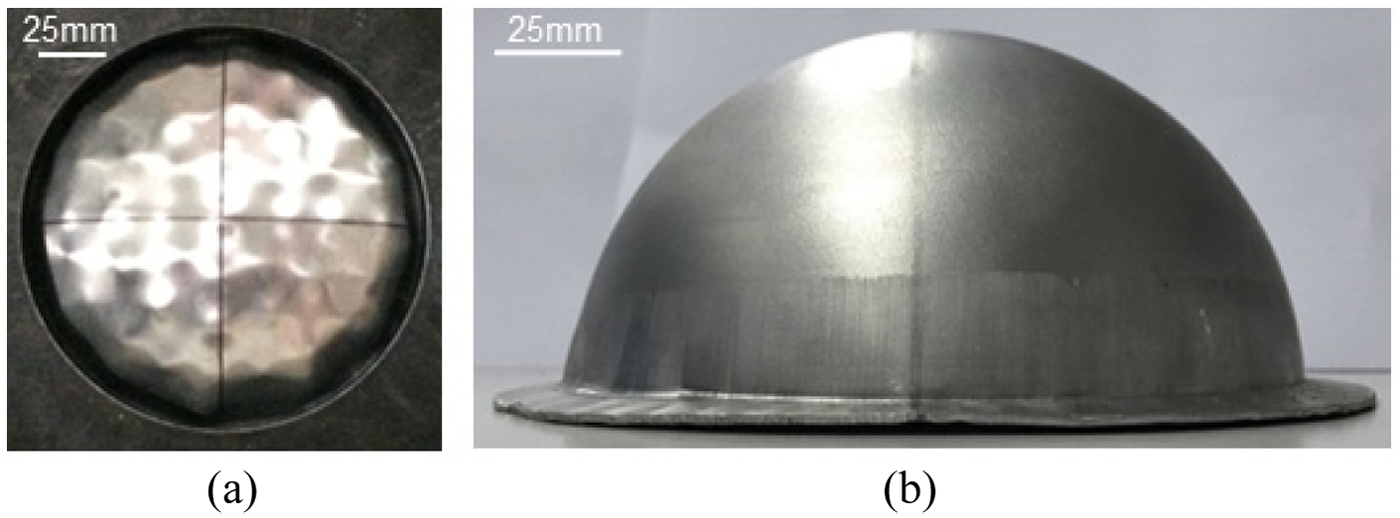
Procedure for hemisphere with the new hybrid ISF process: (a) preforming and (b) final forming.
Thickness prediction model validation
Using the preform shape C3 that given in Figure 9, the predicted and measured thickness distributions are compared as shown in Figure 12. As can be seen in this figure, the minimum thickness obtained from FE modeling is about 0.7 mm, which is similar to the experimental results. The location where the minimum thickness occurs is also predicted with satisfaction. This result suggests the robustness of the developed thickness prediction model. However, some deviations can also be observed around the edge and center of the hemisphere part. These inaccuracies may be because of the limited prediction accuracy of the geometrical approach.
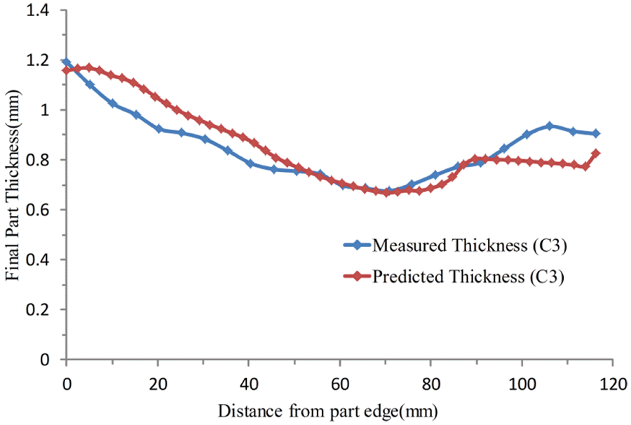
Thickness distribution comparison: prediction and experiment.
Verification of preform optimization
To verify the effectiveness of the preform optimization, forming cases with preform high of 35 and 50 mm are compared. As can be seen in Figure 13, under the drawing depth of 35 mm, the minimum thickness is about 0.5 mm, which implies a thickness reduction of about 60%. When the drawing depth is increased to 50 mm, the minimum thickness increases to about 0.6 mm, which indicates an increase of 10%. This result suggests that increasing drawing depth is a quite effective way to reduce the thickness reduction.
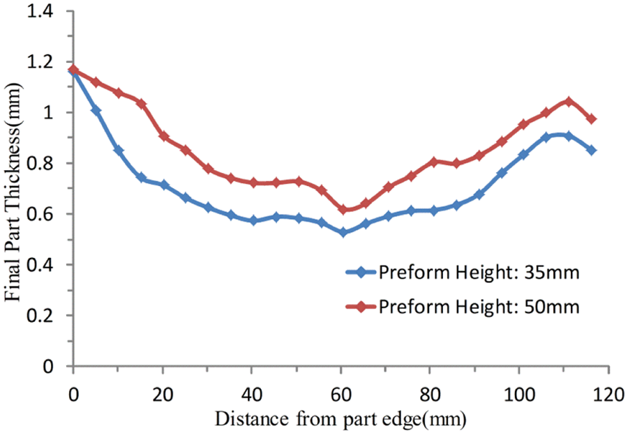
Experimental sheet thickness distribution comparison: preform height of 35 and 50 mm.
Concerning the shape optimization, by holding the drawing depth of 50 mm, thickness distributions before and after the shape optimization are compared as shown in Figure 14. As can be seen in this figure, the distribution of thickness is slightly changed. This is because in the shape optimization, the preform shape can only be modified locally with limited amount. However, due to this optimization, the minimum thickness is further increased to 0.7 mm, which suggests another increase of 10%. This result suggests that optimizing the preform shape could also improve the thickness distribution.
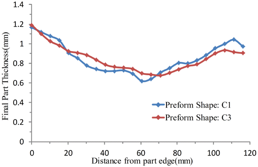
Experimental thickness distribution comparison: preform shape C1 and preform shape C3.
Comparison with the conventional ISF process
To verify the effectiveness of the developed hybrid flexible process, the thickness distributions obtained in both hybrid process and conventional ISF process are compared. For the ISF process, as the wall angle of this hemisphere part approaches 90°, it is difficult to directly produce the part with one forming step. Alternatively, a five-step forming strategy has been employed as shown in Figure 15. In this strategy, four forward forming pass and a backward forming pass are employed.
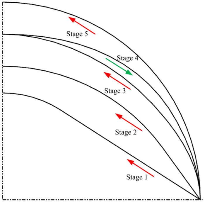
Intermediate steps for multi-step ISF process.
Even with five forming steps, the designed hemisphere part cannot be produced due to the limited formability of 2A12 material. In the experiment, fracture occurs in the third step. The thickness of the failed part is measured, and comparison results are illustrated in Figure 16. As can be seen in this figure, extreme sheet thinning occurs during the ISF process, and the minimum thickness is about 0.46 mm. This thickness is much lower than the value of 0.68 mm that is obtained in the hybrid process. This result suggests that by taking of advantages of drawing and ISF, sheet parts with deep cavity can be fabricated successfully.
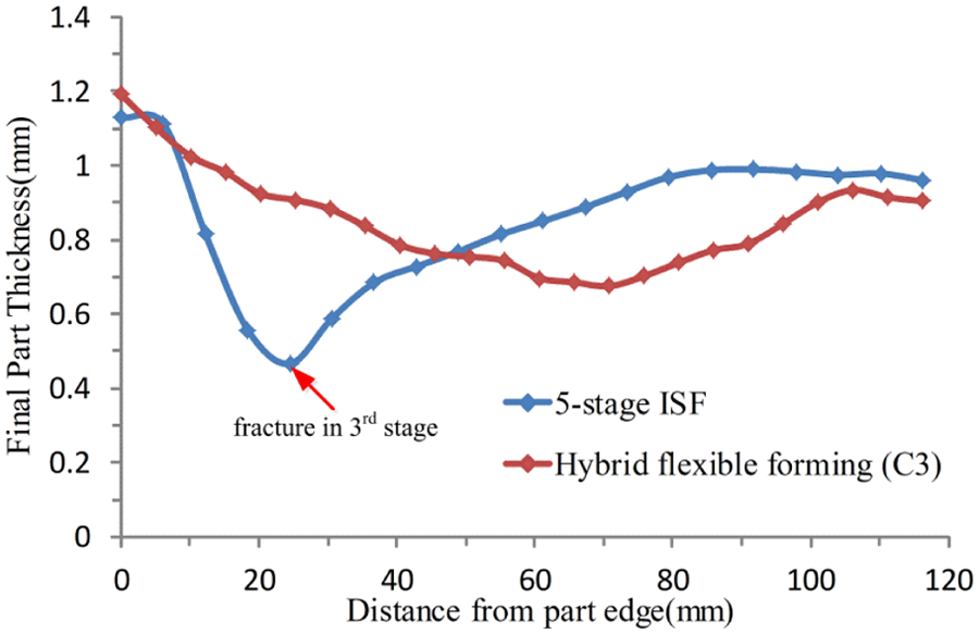
Experiment thickness distribution comparison: five-step ISF process and hybrid flexible forming process.
Case study 2: aerospace cowling
In previous case study, a commonly used hemisphere part has been fabricated with improved thickness distribution. To further validate the enhanced capability of the developed hybrid process, an aerospace cowling part from a real industrial application is investigated in this case study. This part has strict thickness specification to ensure its stiffness and rigidity in service. The geometrical dimensions of this cowling are specified in Figure 17(a), which is 516 mm in length, 156 mm in width and 118 mm in height. As shown in Figure 17(b), the part geometry is mainly controlled by cross sections A-A and B-B; thus, closer attention is paid on these two cross sections in the study. Due to deep cavity features, this part cannot be formed by either deep drawing or ISF approach individually. According to the study by Al-Ghamdi and Hussain, 34 tool radius of 5 mm is a reasonable choice to maintain a high level of formability. However, in this case, considering the large size of the part with corresponding forming efficiency and tool stiffness, 10 mm tool radius has been employed instead. A helical tool path with constant scallop height of 0.005 mm is employed in all the ISF steps to achieve uniform surface roughness.
The designed cowling: (a) part geometry and (b) main frame (mm).
Optimization of drawing depth and preform shape
To determine the best drawing depth, an initial drawing depth of 100 mm is employed. In the first optimization, drawing depth is gradually increased with an interval of 3 mm. The evolution of preform can be observed in Figure 18. As shown in this figure, most of the shape changes occur in the optimization of drawing depth, while there is only limited shape change in shape optimization.
Preform optimization (1–4 are height optimization and 4–5 is shape optimization): (a) cross section A-A and (b) cross section B-B.
Concerning the optimization result, in the initial design, the maximum sheet thinning is about 9.4% in preform and 36.8% in final geometry. With the optimization iterations, the final sheet thickness thinning gradually decreased to a value of 26.7%, as shown in Figure 20 (preform shape 4). However, further increase of forming depth will result in severe wrinkling, and the optimization of drawing depth stops at the value of 109 mm. This result suggests that with the increasing drawing depth, the overall thickness is increased by 10.1%. Based on the drawing depth optimization, as shown in Figure 18, further shape optimization is implemented, and the thickness is increased to about 0.02 mm. After the optimization, the minimum thickness is predicted to be 0.90 mm, and the thickness reduction is about 24.7%. The thickness distributions of preform 1 and preform 5 are compared in Figure 19. As can be seen in this figure, the sheet thickness thinning situation at the top of the cowling has been improved.
Predicted sheet thickness distribution: (a) preform 1 and (b) preform 5.
Concerning the reduction of sheet thickness thinning as shown in Figure 20, the major improvement occurs in the first procedure of increasing the drawing depth (shapes 1–4 in Figure 18). There is only limited improvement in the second procedure of shape optimization (shape 4–5 in Figure 19). This is because, in the second step, as the drawing depth of 109 mm is approaching the total depth of 118 mm, there is only limited space for shape optimization, and the shape is slightly changed in the second optimization step.
Predicted final part maximum sheet thinning during preform optimization.
Experimental validation
Based on the optimized design, experiment has been implemented to validate the numerical results. The finished part is shown in Figure 21(a). As can be seen in this figure, the part can be finished successfully. Thickness on cross section A-A for both experiment and prediction is shown in Figure 21(b). The maximum measured thickness reduction is 25.4% within the industrial tolerance. For the section A at the vertical wall, since the preform shape is almost the same as the final geometry and has no wrinkles in this area, the ISF step does not have much influence on this area, and the prediction values are consistent with the experiment results. For the section B from vertical wall (90°) to about wall angle with 55°, the deviation can be observed, and the prediction result is higher than the measurement. This deviation may be caused by limited accuracy of geometrical approach. For the section C at the top of part, slight deviation can still be observed. New thickness prediction model in ISF process is required to improve the overall thickness prediction.
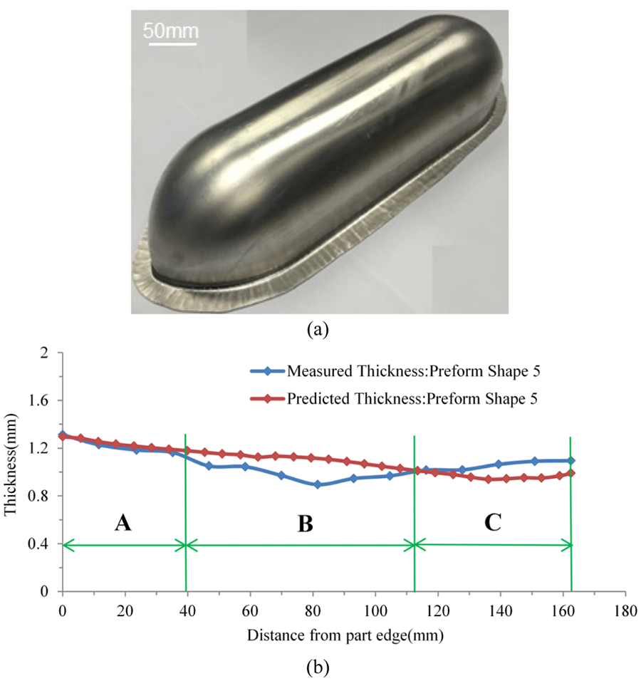
Experiment results: (a) obtained cowling part and (b) sheet thickness distribution on cross section A-A.
Discussion of results
In the conventional ISF process, severe sheet thinning and the resulting limited formability is one of the main constrains for its industrial application. This is especially true for parts with deep cavity, such as the two study cases employed in this article. The hybrid flexible forming process combining both the MPF and the ISF processes becomes a possible solution. Using these two processes, the advantages such as process flexibility, the draw-in effect for material supplement and the localized effect for increased formability are included. The disadvantages such as extreme sheet thinning, long processing time and limited geometric complexity can also be avoided in this hybrid process.
Comparing with the relevant flexible forming process such as ISF, the deformation modes between these two processes are quite different. In ISF, plane strain deformation is the dominant deformation mode, and the thickness reduction is determined by the forming angle. 35 Multi-stage ISF inherits the ISF deformation mode of plane strain, but the thickness reduction is varied for each step according to the deformation order and ratio. 36 However, for the hybrid forming process, as can be observed in this work, the majority of sheet deformation was completed in the MPF step in which the sheet thinning follows the conventional sheet forming deformation mode. At the final forming stage, the deformation mode becomes ISF. However, this deformation is quite limited; thus, the effect from ISF would not be obvious.
Concerning the achieved geometry in the hybrid forming, as it also inherits from ISF, pillow effect and stepped feature may also occur in the forming process. However, for the two cases in this work, no obvious pillow effect can be observed. Possible reasons are (1) the work hardening in the MPF step could reduce the pillow effect and (2) pillow shape occurs in the opposite forming direction and only is left when the part center is flat and unformed. 37 Stepped feature in the forming direction may need to be concerned in the hybrid forming for certain geometric shape.23,38 Instead of bouncing back and causing pillowing, rigid-body motion may push the center material further down, which causes the inaccurate geometry. This effect may be avoided using proper designed intermediate shapes. 33
The remaining challenge of implementing this process is the determination of the drawing depth and the preform shape. To determine these parameters, a simplified thickness prediction model has been developed in this work. To validate this new forming process and corresponding thickness prediction model, two case problems, a hemisphere part and an aerospace cowling, have been fabricated based on the numerical calculation. The experiment results suggest that these parts, which can neither be obtained in the two single processes, could be successfully formed in this hybrid process with good thickness distribution. The hybrid flexible forming process proves to be effective in thickness control and time saving.
However, there are still some limitations in the current process. The accuracy of thickness prediction model is still limited especially for the ISF process. In addition, an uncoupled optimization procedure is employed, and the drawing depth and preform shape are optimized separately. The obtained parameters may not be the global optimum. Improved thickness prediction model and optimization procedure are necessary in the future development.
Conclusion
In this work, a hybrid flexible sheet forming process has been developed to improve the thickness distribution of two sheet metal parts. The process maintains the advantages from both forming processes: the material draw-in effect from MPF process and high formability from ISF process. Numerical models to predict the thickness distribution and optimize the preform parameters have also been developed. Key parameters such as drawing depth and preform shape are determined, and the thickness prediction and optimization models are validated using two case studies. The conclusion of this work may be summarized as follows:
The hybrid process combining MPF and ISF could achieve higher formability comparing to conventional sheet forming processes. This is realized by taking advantage of material inflow in MPF and high formability in ISF.
The hybrid process could fabricate sheet metal parts with improved thickness distribution due to the different sheet deformation modes in MPF process and ISF process. In the hemisphere case, the thickness is improved by 46%. In the case of aerospace fairing, the maximum thickness reduction is only 25.4%.
The hybrid process shows high process flexibility and improved process efficiency. As both MPF process and ISF process are flexible, the combination of the two processes also does not require any specified forming tools. With MPF process, the preform time is greatly reduced compared to multi-stage ISF.
The developed thickness prediction model shows a satisfied modeling accuracy and efficiency. This model has been validated by results obtained from the two case studies. The maximum sheet thinning is predicted accurately in the case of hemisphere, and the maximum thinning prediction error is within 0.15 mm for the aerospace fairing.
Footnotes
Declaration of conflicting interests
The author(s) declared no potential conflicts of interest with respect to the research, authorship and/or publication of this article.
Funding
The author(s) disclosed receipt of the following financial support for the research, authorship, and/or publication of this article: This research was supported by the Advanced Spaceflight Technology Joint Research Center and Lab Co-founded by SJTU and Shanghai Academy of Spaceflight Technology (SAST) and the Marie Curie International Incoming Fellowship within the 7th European Community Framework Programme (628055 and 913055).