
Abstract
In the process of flexible 3D stretch bending, the shape deviation difference between the contact zone and non-contact zone is studied. It is obvious that in the contact zone, the die regulates the deformation of the profile to make it conform to the target shape with small shape deviation; in the non-contact zone, the profile has no die restriction and deviates from the target shape with large shape deviation. When the dies are placed equidistantly along the x-axis, the shape deviation of the non-contact zone near the clamp side is greater than that near the middle of the profile. Arrange the distance between adjacent dies in equal ratio along the x-axis, so that the spacing near the clamp side is a little smaller, and the spacing near the middle of the profile is a bit larger. The difference between the shape deviation of the non-contact zone profile near the clamp side and the middle of the profile decreases, and the maximum shape deviation is reduced, which greatly improves the processing accuracy and quality. However, with the increase of the distance difference between adjacent dies, the shape deviation difference of the non-contact zone near the middle of the profile also increases greatly. Although the clamp side decreases, the maximum shape deviation has become the shape deviation of the profile in the non-contact zone near the middle of the profile.
Keywords
Introduction
In recent years, with the rapid development of modern industrialization, more and more 3D forming parts will be used in automobile, high-speed rail, aircraft, and other manufacturing industries. 3D stretch bending forming technology has broad development space.1–7
The FSB process is an improvement of traditional stretch bending process. In order to realize the rapid production and flexible manufacturing of this bending process, many scholars have studied and optimized it. Wang et al. 8 verified that the multi-point die can completely replace the overall die by comparing the stretch bending forming effect of aluminum profile on multi-point die and overall die; Peng et al.9,10 simulated and analyzed the FSB process of aluminum alloy rectangular tube, discussed the influence of bending radius and section thickness on defect indentation and section distortion of multi-point forming, and proposed the method to limit defects; Liang et al. 11 studied the FSB process of aluminum profile, and elaborated the processing technology of FSB of aluminum profile; Li et al. 12 studied the springback prediction and process optimization of aluminum profiles, and further optimized the FSB process, which improved the stretch bending accuracy of aluminum profiles; but there are still many factors that need to be studied. 13
Due to the composition characteristics of the multi-point stretch bending die, there are contact and non-contact zones between the profile and the die, and the profile shape deviation in the contact zone and non-contact zone directly affects the forming quality of the profile. Lin et al. 14 and Li et al. 15 obtained that the increase of the number of dies improve the forming accuracy of the profile by changing the number of dies. But in the actual production process, the number of dies is often determined, so scientific placement of dies is an effective method to improve the forming accuracy of profiles.
In this paper, based on ABAQUS software, the numerical simulation and experimental research on FSB of aluminum profile are carried out. The difference of profile shape deviation between the contact zone and non-contact zone after forming is explored, and the influence of changing die position on the shape deviation of the non-contact zone profile is studied.
The FSB process
The basic principles and advantages of FSB
The FSB is a forming method in which the whole die is discretized into several roller dies which can be adjusted independently at different positions, so as to form different target shapes.16–22 This forming method can be used for multiple purposes with one machine, reducing production costs, and improving production efficiency. Figure 1 is the schematic diagram of the overall die stretch bending forming and multi-point die stretch bending forming.
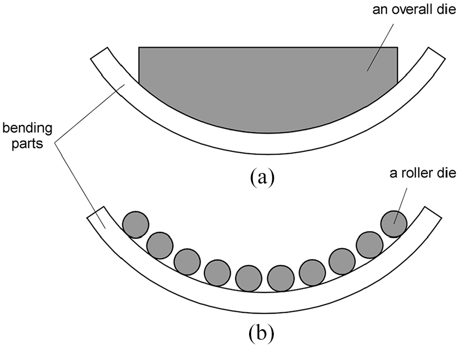
Overall die stretch bending and multi-point die stretch bending: (a) overall die formatting and (b) multi-point die formatting.
The FSB equipment is shown in Figure 2. Each roller die is independently regulated and can move and rotate freely in horizontal and vertical directions. Compared with traditional overall die stretch bending, The FSB has more flexibility and diversity. The process of FSB is as follows: (1) Adjust the position of the dies; (2) Torsion deformation; (3) Horizontal stretch bending; (4) Vertical bending forming; (5) Post-stretching; (6) Unloading.
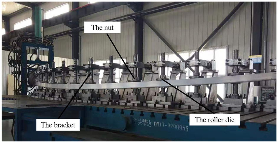
The FSB equipment.
The finite element model
The FSB machine adopts the rotating arm traction mode to realize the bending of the profile, and its main structure is shown in Figure 2. The roller die is sleeved on the bracket with adjustable universal angle, and the position can be limited by the nut. The bracket is fixed on the worktable by the bracket seat. By adjusting the position of the roller die, the given target shape can be formed, and under the traction of the clamp, the profile can fit the die to complete the stretch bending process.
According to the working principle of the FSB machine, the whole FSB machine is simplified as a rigid body model that will not deform during the bending process: roller die. Therefore, only the die surface in contact with the profile is reserved for subsequent simulation analysis. As the main deformation object for analysis and calculation, the profile needs to accurately describe the initial shape and size, and the thin-walled cylinder ring with the same external contour as the profile is used as the clamp and bound with the end of the profile. The finite element model of the roller die and clamp is shown in Figure 3. The bending angle of the profile is 10°.
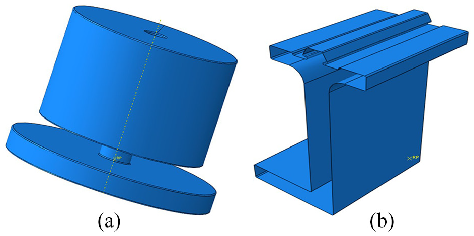
Finite element models: (a) the roller die and (b) the clamp.
Because the profile structure is symmetrical, and in order to shorten the simulation time, 1/2 profile is used for modeling. Therefore, symmetry constraints are used on the symmetrical side boundaries of the profile to ensure the accuracy of simulation.
The clamp and die are modeled with rigid shell structures, and the profile is modeled with deformed body. The profile is meshed with an eight-node linear hexahedral element C3D8R; while the roller die, bracket and clamp are meshed with a four-node 3D bilinear rigid quadrilateral element R3D4.
Material parameters
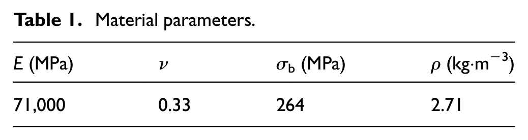
In this paper, an L-shaped profile with a length of 6000 mm is used to simulate the FSB process. Aluminum profile 6005A is selected, and its material parameters are shown in Table 1. The shape and size parameters are shown in Figure 4.
Material parameters.
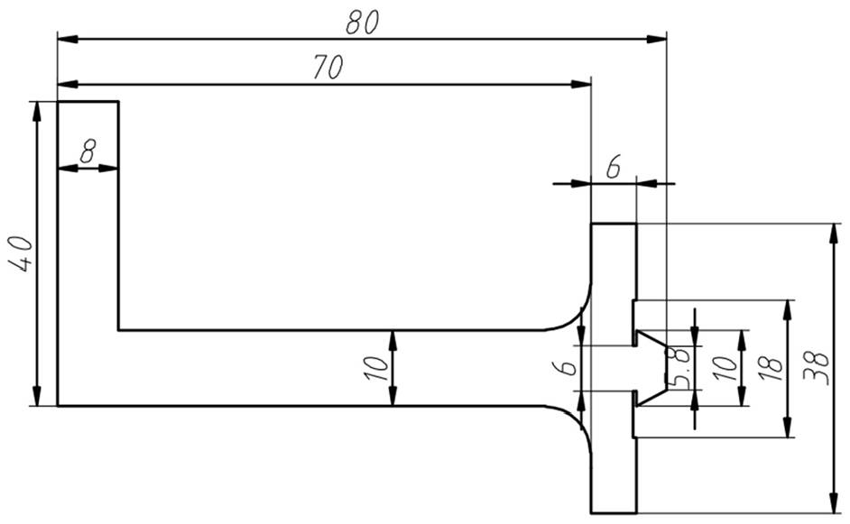
The cross-section size of profile.
Shape deviation analysis of FSB
In FSB process, there are intervals between adjacent dies, that is, there are the contact and non-contact zones between the profile and the die after stretch bending deformation. The shape deviation of the profile in the contact zone and the non-contact zone directly affects the forming accuracy and quality of the profile. In this paper, the change rule of profile shape deviation in the contact zone and non-contact zone is explored, and when the number of dies is determined, the shape deviation of the profile is reduced by changing the position of the die.
Determine the position of the die
According to the requirements of the processing target shape, we can obtain the bending angle θ of the profile, from which the bending radius R of the profile can be obtained.

Where L is the length of the profile after forming.
The coordinate position of the die centroid (xdie, ydie) is taken as the reference point of the whole die, and the y-axis coordinate ydie of the die is obtained by formula (2).
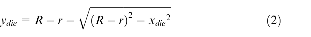
Where xdie is the x-axis coordinate of the die and r is the radius of the roller die.
The influence of die equidistant placement on profile shape deviation
Adjacent roller dies are placed at an interval of 200 mm along the x-axis. The x-axis coordinate of the ith die is xi, and there are 15 dies. The x-axis coordinate of the last die is 2800 mm. The y-axis coordinate yi of the die can be determined by substituting the x-axis coordinate xi of the die into formula (2), and the die placement position is shown in Figure 5.
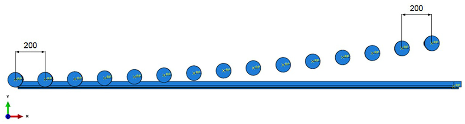
The die is placed at equal distance.
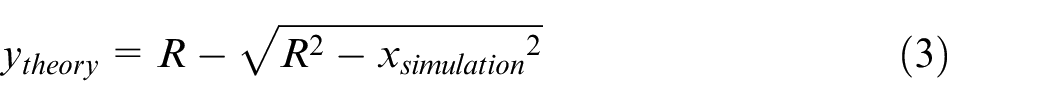
After horizontal stretch bending simulation, the position of each node (xsimulation, ysimulation) is output along the path a (as shown in Figure 6), and the theoretical bending position ytheory of each node is calculated by formula (3), and the difference between them is the shape deviation of profile.
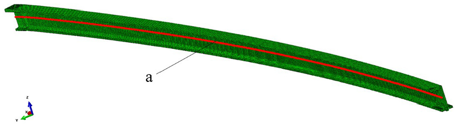
The location of path a.
The shape deviation of the profile when the die is placed equidistantly is shown in Figure 7. It can be seen from the figure that the deformation of the profile is regulated by the die in the contact zone to make it conform to the target shape, and the shape deviation is small; in the non-contact zone, the profile deviates from the target shape without the limitation of the die, and the shape deviation is large. Therefore, the shape accuracy of the FSB process depends on the shape deviation of the non-contact zone. And near the middle of the profile, the profile shape deviation of the non-contact zone is small, and near the clamp, the profile shape deviation of the non-contact zone is larger. And there is a rule that the shape deviation gradually increases from the middle of the profile to the clamp, which shows that the die has different effects on the deformation of the non-contact zone at the same interval, and the constraint on the profile in the non-contact zone near the clamp is less than that near the middle of the profile, the forming effect is shown in Figure 8.
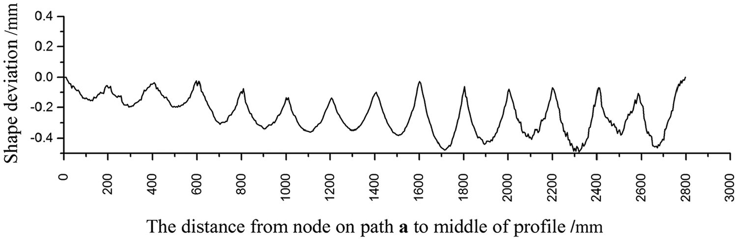
The shape deviation of the profile when the die is placed equidistantly.
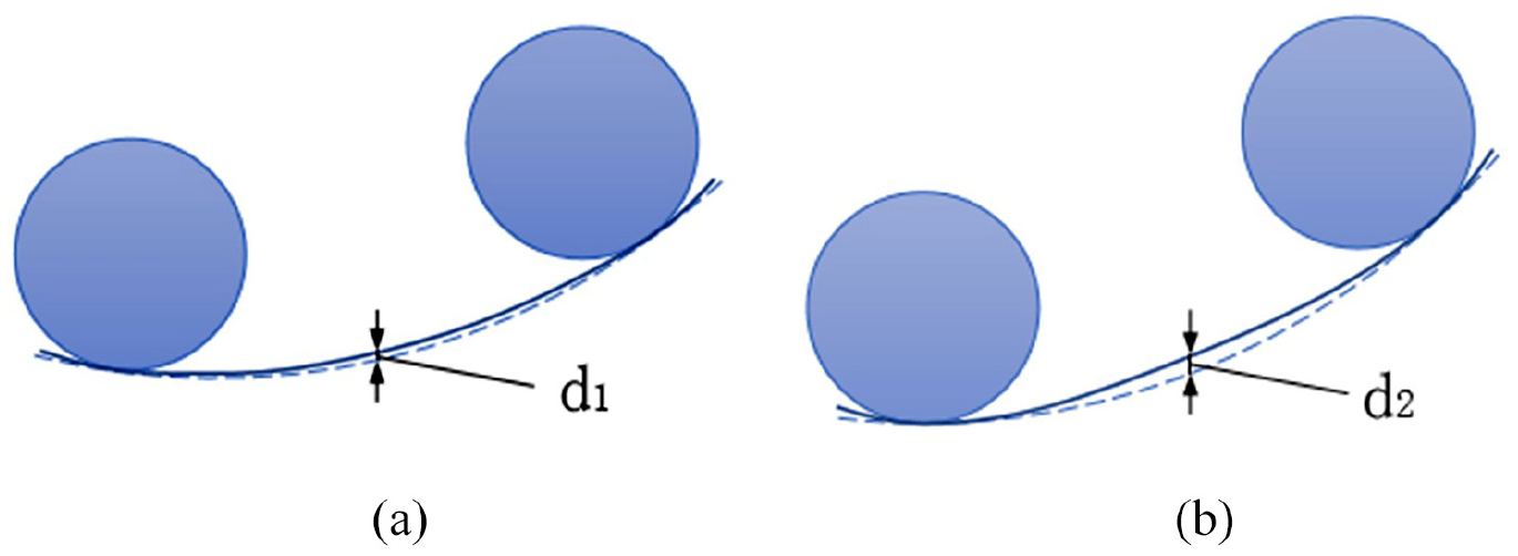
Comparison of profile shape deviation in non-contact zone at different positions: (a) near the middle of the profile and (b) near the clamp side.
There are two reasons for this situation. One is that when one end of the profile is fixed without dies, the change of bending deflection is different at the side near the clamp and the middle of the profile, resulting in different bending curvature of the profile on both sides. The bending curvature of the profile near the clamp is small, and the profile is close to a straight line, while the profile has a larger curvature away from the clamp, as shown in Figure 9.
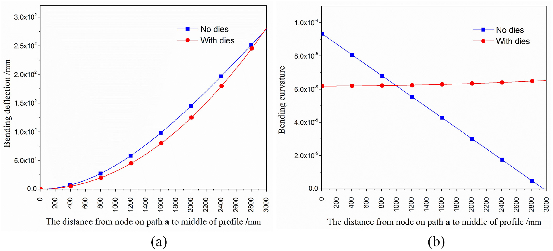
Comparison of the bending shape and bending curvature of the profile with or without the die: (a) comparison of the bending shape and (b) comparison of bending curvature.
The other is that the profile is stretched axially in the bending process. By analyzing the distance between adjacent nodes along the path a, it is found that the element length near the clamp side is larger than that far away from the clamp. The results are shown in Figure 10.
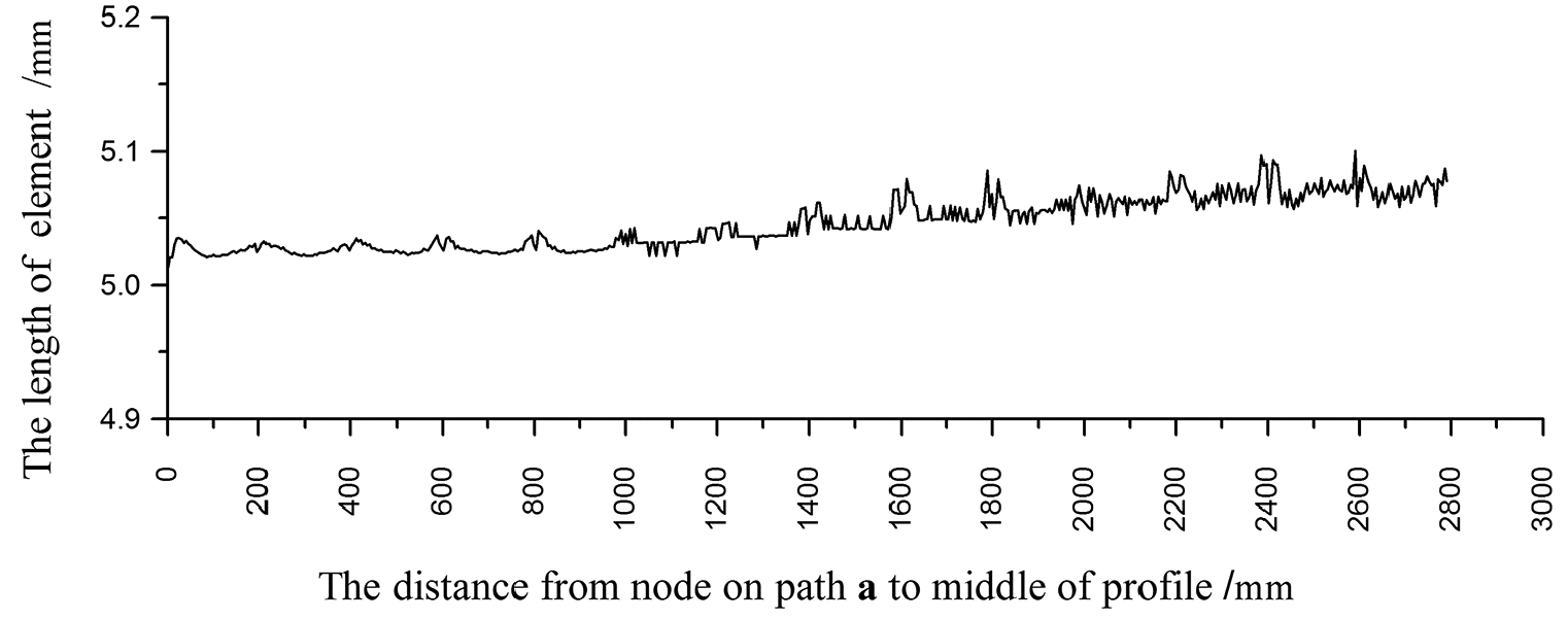
The element length changes along path a.
The influence on profile shape deviation when the die is placed in equal ratio
Equal ratio placement means that the ratio of the distance between each die and the front and rear dies in the x-axis direction is a fixed value q (called the common ratio), that is

The shape deviation of the profile in the non-contact zone near the clamp side is greater than that near the middle of profile when the die is placed equidistantly. In order to reduce the difference of the shape deviation between the two sides, the die needs to be placed at a smaller interval near the clamp side and a little larger near the middle of profile, so we use equal ratio placement.
In order to compare the difference between the two methods, the die in the range of 0–2800 mm is repositioned, and the change rule of profile shape deviation in non-contact zone is explored without increasing the number of dies. The distance of adjacent dies along the x-axis direction is allocated according to the common ratio q. According to formula (5), the distance a1 along the x-axis between the first dies and the second die is calculated.
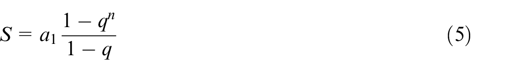
Where S is the length from the first die to the last die, S = 2800. n is the number of intervals between adjacent dies, n = 14, q is the ratio of the distance between each die and the front and rear dies, q = 0.98.
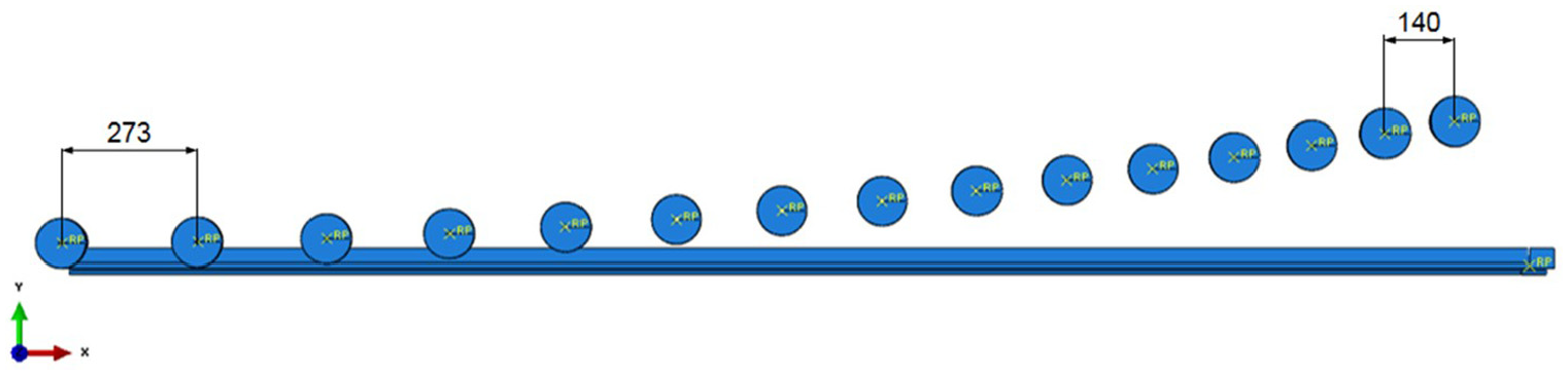
According to formula (6), the x-axis coordinate xi′ of each die is obtained, and xi′ is brought into formula (2) to obtain the y-axis coordinate yi′. The assembly result is shown in Figure 11.
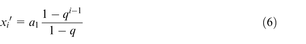
Where i is the ith die, i = 1, 2, 3, 4, …, 15
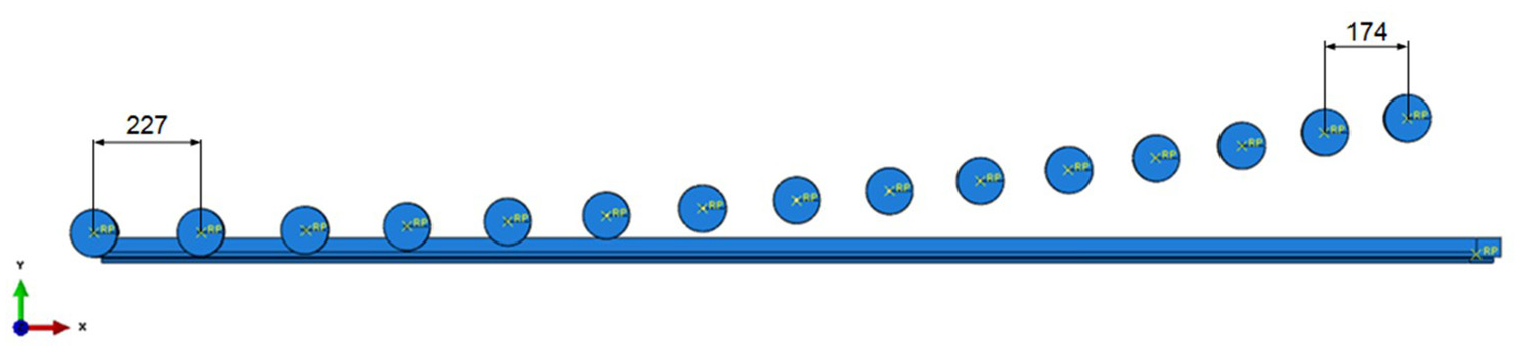
The die is placed in equal ratio, q = 0.98.
After horizontal stretch bending simulation, the position of each node (xsimulation′, ysimulation′) is output along the path a (as shown in Figure 6), and the theoretical bending position ytheory′ of each node is calculated by formula (3).
The shape deviation of the profile when the die is placed in equal ratio is shown in Figure 12. From the figure, although the shape deviation of the profile in the non-contact zone near the middle of profile increases, the shape deviation of the profile in the non-contact zone near the clamp side is greatly reduced, which decrease the maximum shape deviation of the profile and improve the forming accuracy and precision.
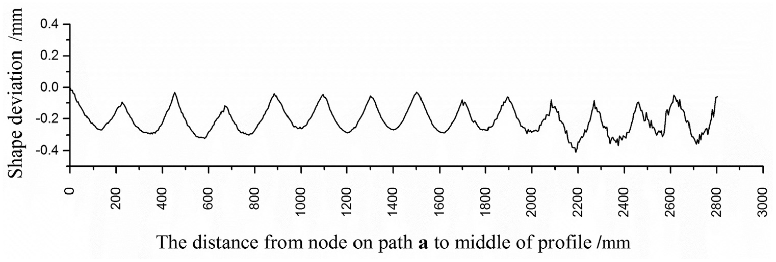
The shape deviation of profile when die is placed in equal ratio, q = 0.98.
By changing the value of q, take q = 0.95, re-determine the distance a1′ between the first die and the second die along the x-axis according to formula (5), and calculate the placement position of each die according to formula (6). The assembly result is shown in Figure 13.
The die is placed in equal ratio, q = 0.95.
After horizontal stretch bending simulation, the position of each node (xsimulation″, ysimulation″) is output along the path a (as shown in Figure 6), and the theoretical bending position ytheory″ of each node is calculated by formula (3). The obtained profile shape deviation is shown in Figure 14. It can be concluded from the figure that with the increase of the difference of adjacent spacing distance, the profile shape deviation of the non-contact zone near the middle of profile increases greatly. Although the clamp side decreases, the maximum difference has become the shape deviation of the non-contact zone near the middle of the profile, which will lead to the decline of the quality and precision of the profile forming.
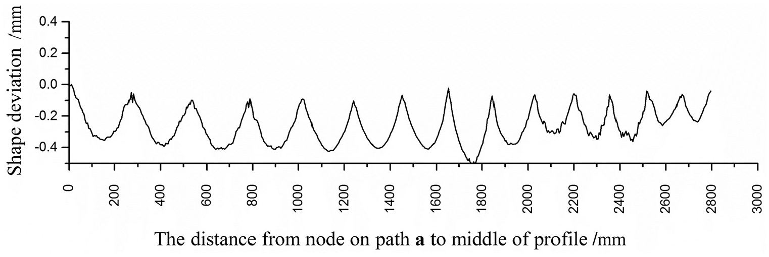
The shape deviation of profile when die is placed in equal ratio, q = 0.95.
The FSB experiment
In this experiment, a FSB machine is used to stretch bending a 6000 mm L-shaped aluminum profile, as shown in Figure 15. Scan and analyze the forming parts with the NDI large space measuring instrument PRO CMM3500 optical tracker.
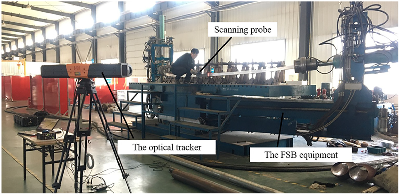
The FSB experiment.
The bending displacement in the middle of the non-contact zone of the inner curved surface is selected to output the data, and the numerical comparison is made with the same part of the finite element model. The result is shown in Figure 16. It is found that the shape deviation of the non-contact zone after stretch bending is basically consistent with the experimental results, which proves the effectiveness of the numerical simulation results.
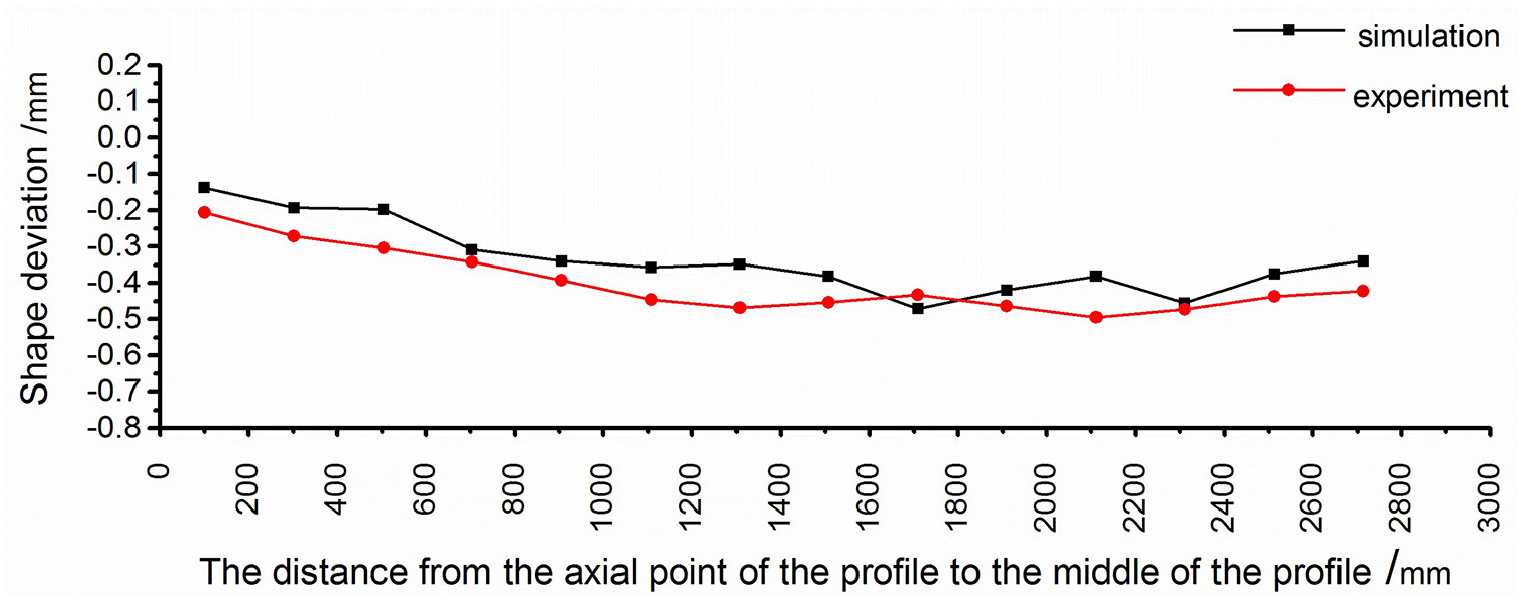
The shape deviation difference between experiment and simulation.
Conclusion
After the process of stretch bending, in the contact zone, the die regulates the deformation of the profile to make it conform to the target shape, and the shape deviation is small; in the non-contact zone, the profile deviates from the target shape and the shape deviation is large.
When the dies are placed at equal distance along the x-axis direction, the profile shape deviation in the non-contact zone near the clamp side is greater than that near the middle of profile. There are two reasons for this situation. One is that when one end of the profile is fixed without dies, the change of bending deflection is different at the side near the clamp and the middle of the profile, resulting in different bending curvature of the profile on both sides. The bending curvature of the profile near the clamp is small, and the profile is close to a straight line, while the profile has a larger curvature away from the clamp. The other is that the profile is stretched axially in the bending process, and the stretching length of the profile near the clamp side is greater than that near the middle of the profile, which leads to the bending curvature near the clamp side less than that near the middle of the profile.
By using equal ratio placement, the spacing of the die placed near the clamp side is smaller, and the spacing near the middle of the profile is larger. The shape deviation difference between the clamp side and the middle of the profile in the non-contact zone decreases, and the processing accuracy and quality of the profile are greatly improved. However, if the difference between the die placement distances is too large, the shape deviation of the profile in the non-contact zone near the middle of profile will become larger, resulting in the decline of the profile processing accuracy and quality.
Footnotes
Declaration of conflicting interests
The author(s) declared no potential conflicts of interest with respect to the research, authorship, and/or publication of this article.
Funding
The author(s) disclosed receipt of the following financial support for the research, authorship, and/or publication of this article: This work was funded by the Project of Jilin Provincial Scientific and Technological Department (20190302037GX, 20190201110JC); the China Postdoctoral Science Foundation (2017M611321); Project of Jilin Province Development and Reform Commission (2019C046-2).