
Abstract
In the flexible stretch bending of multi-point roller dies process, the deformation of workpiece is mainly driven by clamps. Therefore, the movement track of clamp has a great influence on the forming effect of workpiece. Y-profile, T-profile, and L-profile are taken as the research objects. Simulation and experiments are carried out with two different movement tracks. The influence of the movement tracks on shape error, springback error, and thickness variation of different profiles is discussed. The experimental results of the three profiles processed by the double-sided forming method are consistent with the simulation results, which proves the accuracy of the numerical simulation. The results show that the movement track has a great influence on shape error. Compared with double-sided forming, one-sided forming can effectively reduce springback error. The two different movement tracks have no obvious influence on thickness change.
Introduction
There are various processing methods for profiles, and stretch bending is one of the main technologies for processing profiles. Compared with press bending and rotary draw bending forming, stretch bending has the advantages of high forming accuracy and small springback. It is usually suitable for the forming of solid or hollow profiles with large axial length, diversified cross-sections, and complex spatial shapes.1,2 In stretch bending process, typical forming defects include shape error, springback, cross-section distortion, and space distortion, which are all defined by mathematical methods. Welo and Baringbing 3 studied the influence of important parameters on the dimensional accuracy of stretch bending. Using the theory of plastic deformation, a model for predicting longitudinal stretching and transverse bending deformation was established. This model could be used to predict cross-section distortion. Liu et al. 4 studied the influence of the post-stretching elongation on forming defects. On the basis of numerical simulation, the influence of different post-stretching elongation on forming defects was discussed.
When the thin-walled rectangular tube is plastically bent during the stretch bending process, obvious cross-sectional distortion occurs. In order to minimize the deformation, Zhu and Stelson 5 used a fixed wall to limit the protrusion of the tube side wall. And he found that internal pressure could also be used to compensate for deformation. In order to judge the fracture limit of the aluminum-lithium alloy, Liu et al. 6 used theoretical methods to predict the minimum bending radius of stretch bending. Simultaneously, finite element simulation was carried out and compared with experiment. Zhao et al. 7 discussed the different stress and strain distributions of any cross-section profile in the stretch bending process. A general analysis method was obtained to solve the springback problem of plane bending. Gu et al.8–10 analyzed the causes of defects such as wrinkling, cross-section distortion, and low shape accuracy, and proposed corresponding control methods. The results show that the proposed control method is quite effective and realizes the large-scale production of high-precision bending parts. Yu and Li 11 studied the theoretical analysis of springback in the stretch bending process of L-profiles. According to the stress and strain distribution of the workpiece section, a characterization model of the springback angle after unloading was established.
In recent years, many scholars have made innovations in the field of stretch bending technology. Muranaka et al. 12 proposed a new “rubber-assisted stretch bending method” for uniform bending of profiles with a constant radius of curvature. Deng et al. 13 studied the material characterization and constitutive model of titanium alloy in uniaxial tension and stress relaxation. A heatable stretch-bending process was proposed to improve the forming stability of titanium alloy profiles and reduce springback. Schilp et al. 14 proposed a method of applying plastic forming in the main process without changing the design of dies. This method has been successfully applied to the stretch bending process of manufacturing aerospace, aircraft, and automobile parts.
Flexible forming technology has been widely used in industries such as construction, rail trains, ships, aircraft manufacturing, and skull repair.15–17 This technology has received widespread attention due to its die surface reconfigurability and reusability in the forming process of different parts. 18 Liang J and Li Y et al.19,20 proposed a flexible three-dimensional stretch bending forming technology, which achieved a breakthrough in one-time forming of profiles from two-dimensional to three-dimensional deformation.
The flexible stretch bending of multi-point roller dies (FSB-MPRD) technology is a new type of flexible three-dimensional stretch bending technology.21,22 In the forming process of FSB-MPRD, the deformation of workpiece is mainly driven by clamps. Therefore, the movement track of the clamp has a great influence on the forming effect of workpiece. Previous work has little research on the movement track of the clamp. In this paper, the finite element model of FSB-MPRD is established with Y-profile, T-profile, and L-profile as the research objects. The influence of two different movement tracks of clamp on shape error, springback error, and thickness variation of the workpiece is discussed. The corresponding experiments are carried out with FSB-MPRD forming equipment.
FSB-MPR forming technology
Forming principle
FSB-MPRD forming process is to separate the traditional stretch bending die into several multi-point roller dies (MPRD), so that the workpiece can be deformed in 3D space. This process meets the needs of multi-directional deformation of workpiece in space, and can be used to form three-dimensional parts. 21 Figure 1 shows the forming principle of the FSB-MPRD process. It can be seen from Figure 1 that the MPRD are installed on the flexible foundation unit (FFU), which is arranged regularly and has adjustable shape. Through the precise control of each FFU and the independent adjustment of MPRD, the forming surface of three-dimensional stretch bending can be constructed.
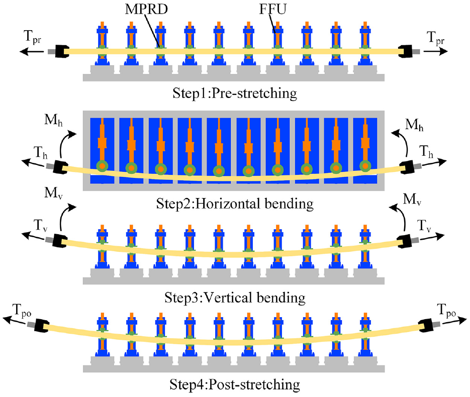
The forming principle of FSB-MPRD process.
As shown in Figure 1, the FSB-MPRD forming process can divide the 3D deformation of workpiece into four steps. The first step is to make the workpiece reach the plastic state in advance, that is, pre-stretching. In the second step, the workpiece is driven by the clamp to get close to the dies until it is fully contacted with the last roller die to complete horizontal bending in X-Y plane. In the third step, after the horizontal bending, the profile is driven by the clamp and the dies to produce a certain displacement in the vertical plane, and the vertical bending of the profile is finished in X-Z plane. In the fourth step, the workpiece needs to be post-stretched to reduce the springback error after 3D deformation.
Figure 2(a) shows the equipment diagram of the FSB-MPRD process. The number of FFU can be increased or decreased according to the length of workpiece. In horizontal bending process, the maximum rotation angle of the robot arm can reach 120°. The maximum bending angle of the robotic arm can reach 60° during vertical bending process. This equipment can produce workpieces with different lengths and various types of profiles. Figure 2(b) is a measuring equipment used to measure the shape error and springback error of the formed workpiece.
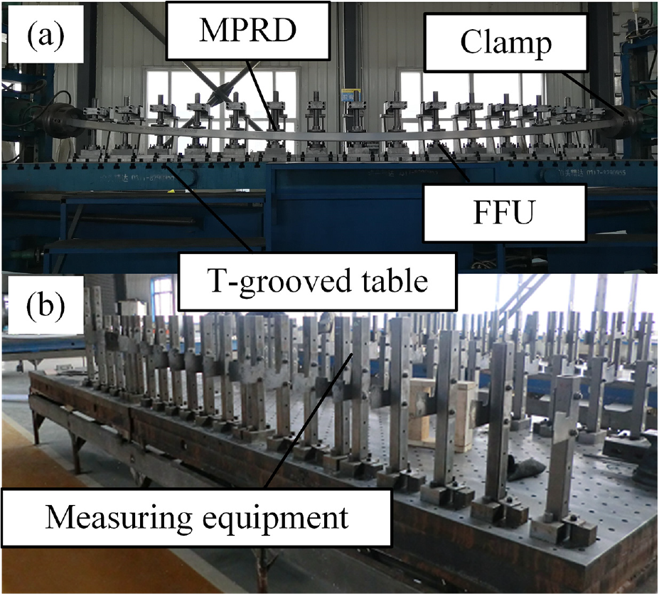
Experimental equipment and measuring equipment: (a) FSB-MPRD experimental equipment and (b) measuring equipment.
The movement track of the clamp
In order to further explore the forming process of FSB-MPRD, the influence of different movement track of the clamp on workpiece is studied. The difference in movement tracks is mainly reflected in the horizontal bending process, as shown in Figure 3. Double-sided forming means that in the horizontal bending process, the clamps at both ends move at the same time to drive the workpiece close to the dies until the horizontal bending ends as shown in Figure 3(a). One-sided forming means that in the horizontal bending process, one end of the workpiece is fixed by a clamp, and the other end is driven by the clamp to close the dies as shown in Figure 3(b). Two different movement tracks make the workpiece in two completely different stress states. And during the horizontal bending process, the movement track of clamp has a great influence on the vertical bending of the workpiece.
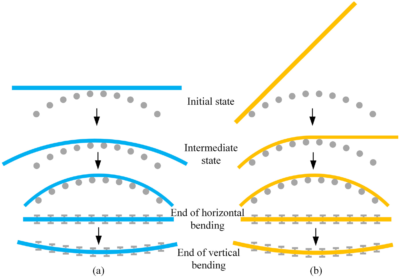
The movement track of the clamp: (a) double-sided forming and (b) one-sided forming.
Experimental steps
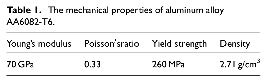
In this paper, AA6082 aluminum alloy under T6 heat treatment state was selected for numerical simulation and forming experiments. The mechanical properties of the aluminum alloy were tested by uniaxial tensile test, as shown in Table 1.
The mechanical properties of aluminum alloy AA6082-T6.
In this paper, Y-profile, T-profile, and L-profile are taken as the research objects, and the influence of two different movement tracks on FSB-MPRD forming process is studied. The length of workpiece is 3000 mm, the horizontal bending radius Rh is 2500 mm, and the vertical bending radius Rv is 7000 mm. The target shape of workpiece is shown in Figure 4(a) and (b). Figure 4(c) to (e) show the section shapes of Y-profile, T-profile, and L-profile respectively.
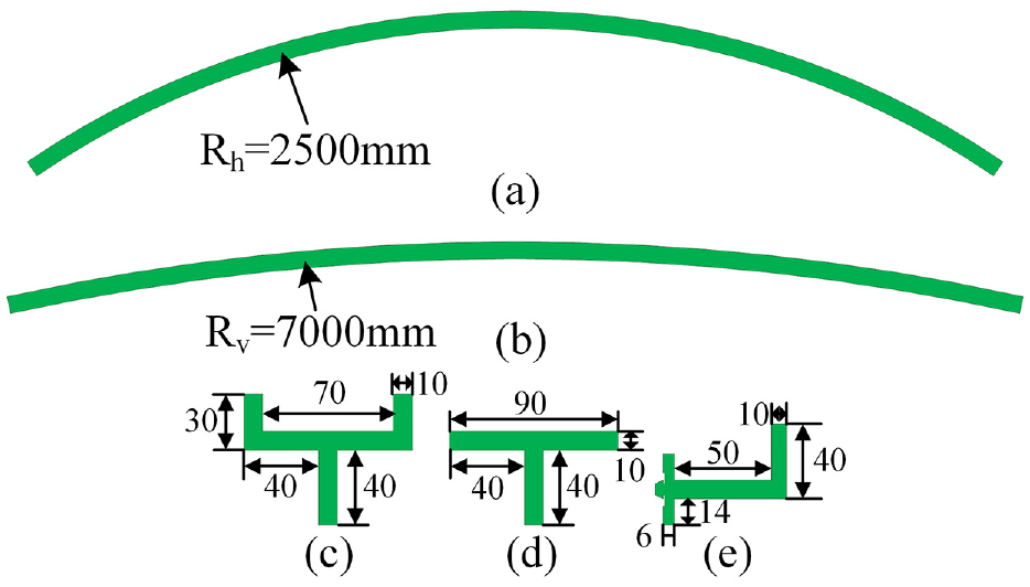
The target shape of workpiece: (a) horizontal bending target shape, (b) vertical bending target shape,(c) Y-profile, (d) T-profile, and (e) L-profile.
Numerical simulation
Establishment of finite element model
In the forming process of FSB-MPRD, the workpiece is deformed greatly. Therefore, the commercial finite element software ABAQUS/Explicit is used for numerical simulation analysis in this paper. In order to improve the forming accuracy, the movement of the dies and the clamp is used for displacement control. First, simplify the model based on FSB-MPRD forming equipment and create parts. Then, according to the section and length of the workpiece, design the roller dies and determine the number of dies. Finally, the parts are imported into the assembly module to form a finite element model.
After the model is established, it is also necessary to define the interaction between the workpiece and the dies, set material properties, set boundary conditions, and meshing.21,23 The workpiece is meshed with C3D8R solid element, and the clamps and roller dies are meshed with R3D4 rigid body element. Taking the T-profile as an example, the established finite element model is shown in Figure 5. When submitting a job, double-precision is used for calculation, which helps to improve calculation accuracy. In addition, the ABAQUS/Implicit algorithm is used to calculate the springback simulation of the deformed workpiece. The load and boundary conditions are deleted in the springback calculation to observe the springback phenomenon of the workpiece after unloading.
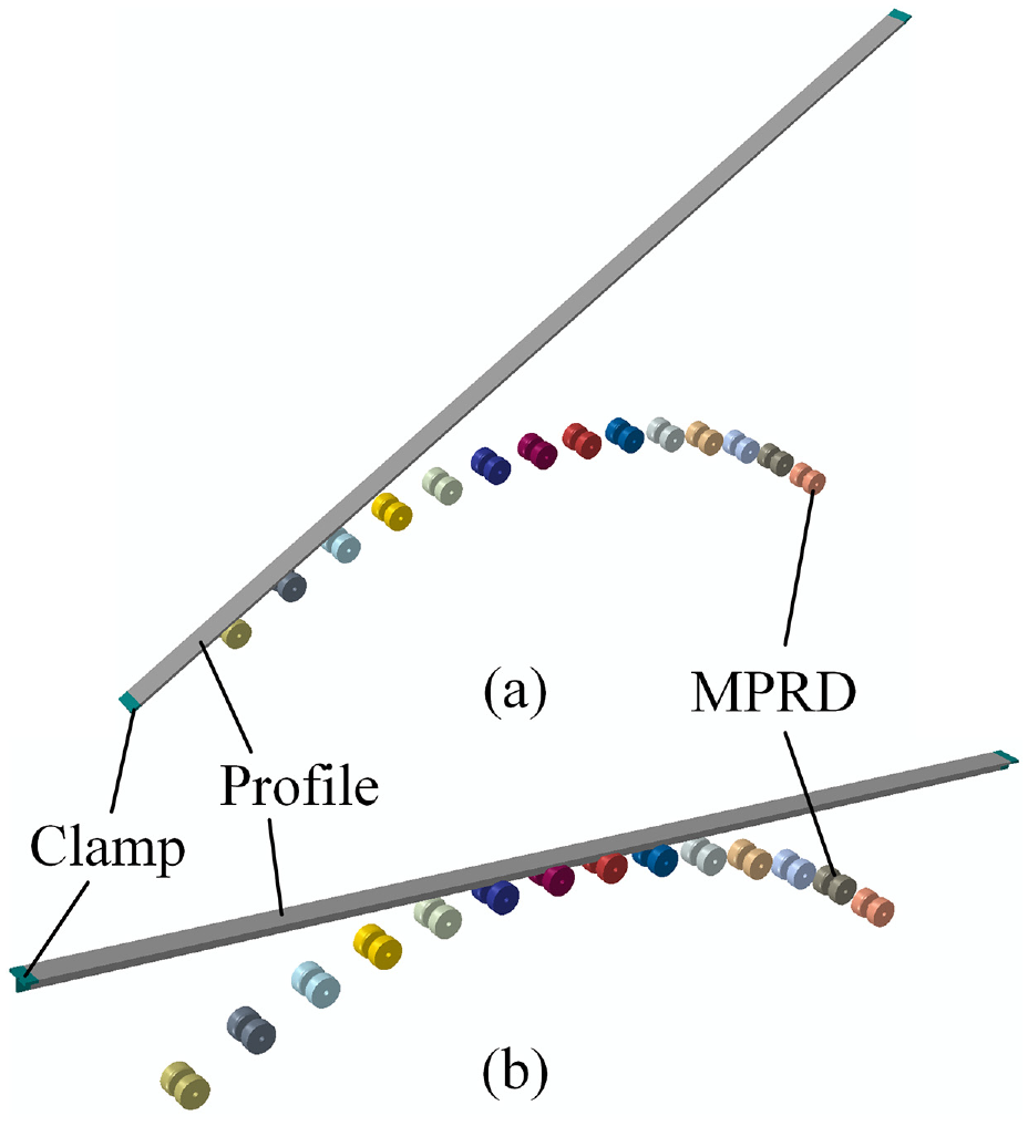
Assembly drawing of the finite element model:(a) one-sided profile and (b) double-sided forming.
Design of movement tracks
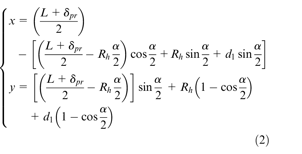
Liang et al. 21 had fully described the movement track design problem of the clamp in the forming process of FSB-MPRD. This paper mainly studies the movement track of the clamp during the horizontal bending forming process, as shown in Figure 6. In the one-sided forming process, the movement track of the clamp can be written as:
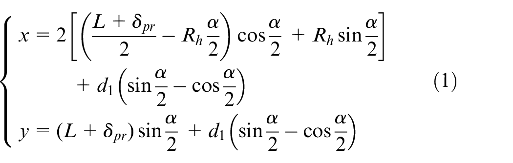
where x is the distance the clamp moves along the x-axis, y is the distance the clamp moves along the y-axis. L is the length of workpiece, δpr is the pre-stretching length, and
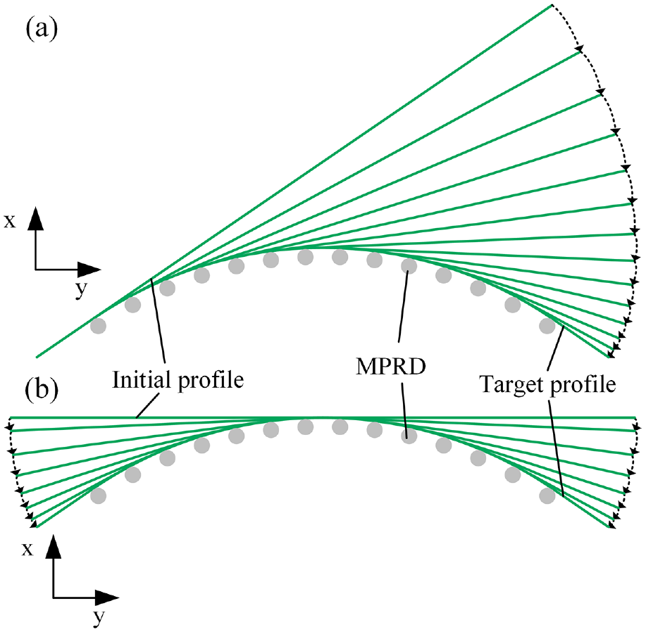
Design of movement track in the horizontal bending process: (a) one-sided forming and (b) double-sided forming.
In the double-sided forming process, the movement track of the clamp can be represented as:
Results and analysis
Analysis of shape error
Shape error refers to the deviation of the formed workpiece from the target shape, which is one of the inevitable defects in the field of plastic forming. In order to analyze the shape error of workpiece, the shape error Yerr in the horizontal bending plane can be expressed as:

the shape error Zerr in the vertical bending plane can be written as:

Among them, Yerr is the horizontal bending shape error along the Y-axis; Y0 is the node value of the target shape; Yi is the node value of the i-th node after the workpiece is formed. Zerr is the vertical bending shape error along the Z-axis; Z0 is the node value of the target shape; Zi is the node value of the i-th node after the workpiece is formed.
Figure 7 shows the shape error curve of different cross-section profiles formed by different movement tracks of clamp. As shown in Figure 7(a), (c), and (e), the horizontal bending shape error of Y-profile, T-profile, and L-profile formed by one-sided forming are smaller than that of profiles formed by double-sided forming. This is because the profile undergoes greater plastic deformation during the one-sided forming process, and the deformation is more uniform. Each trough represents the contact area between the profile and the dies, and the forming accuracy is higher. The shape error between the trough and the trough increases first and then decreases, which indicates that the non-contact area between the profile and the die does not have ideal deformation and the forming accuracy is lower. But the maximum shape error is less than 5 mm, which has met the product requirements of workpiece.
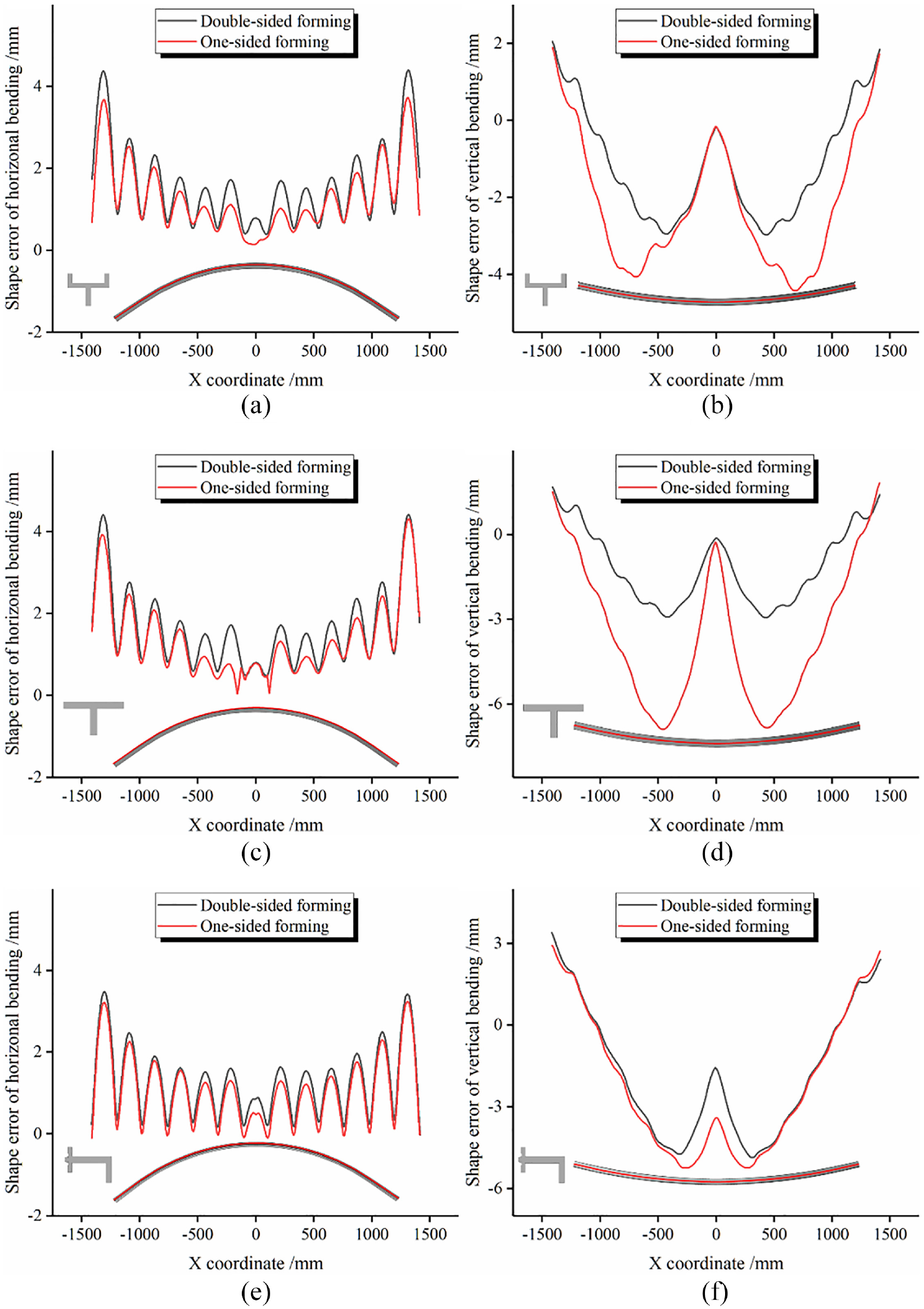
Shape error curve: (a) horizontal bending shape error of Y-profile, (b) vertical bending shape error of Y-profile,(c) horizontal bending shape error of T-profile, (d) vertical bending shape error of T-profile, (e) horizontal bending shape errorof L-profile, and (f) vertical bending shape error of L-profile.
Moreover, it can be seen from Figure 7(b), (d), and (f) that the vertical bending shape error of Y-profile, T-profile, and L-profile is larger than that of profiles formed by double-sided forming. This is caused by the shaking of the profile during the horizontal bending process. Compared with the double-sided forming, the profile formed by one-sided forming is driven by a clamp. When the profile is close to the dies, it shakes more violently on the plane perpendicular to the horizontal bending. From the middle of the profile to the two ends, the vertical bending shape error increases first and then decreases, and the error in the middle of the profile is the smallest. This is because the middle position of the profile is in a fixed state during the vertical bending forming process, and the clamps at both ends are loaded at the same time, which causes the material flow to fail to keep up with the speed of the clamp movement and increases the shape error from the middle to the ends of the profile.
Analysis of springback error
Springback is a phenomenon in which the shape and size of the workpiece deviate from the target shape due to the elastic recovery of the residual stress after workpiece is unloaded. Therefore, the springback defect is also one of the unavoidable defects in the plastic forming field. Figure 8 is the springback error curve of different cross-section profiles by different movement tracks of clamp. As shown in Figure 8(a), (c), and (e), the maximum springback errors of horizontal bending of Y-profile, T-profile, and L-profile formed by one-sided forming are 4.14, 5.56, and 23.78 mm, respectively. For the three profiles formed by double-sided forming, the maximum springback errors of horizontal bending are 10.22, 12.01, and 24.89 mm respectively. Therefore, the springback errors of horizontal bending of the profiles formed by one-sided forming are much smaller than that of the profiles formed by double-sided forming. And the maximum springback error of the right side of the profile formed by one-sided forming is smaller than that of the left side. The main reason for this phenomenon is that in the process of horizontal bending, one-sided forming makes the profile deformation more uniform, increases the plastic deformation degree of the profile, and reduces the springback error.
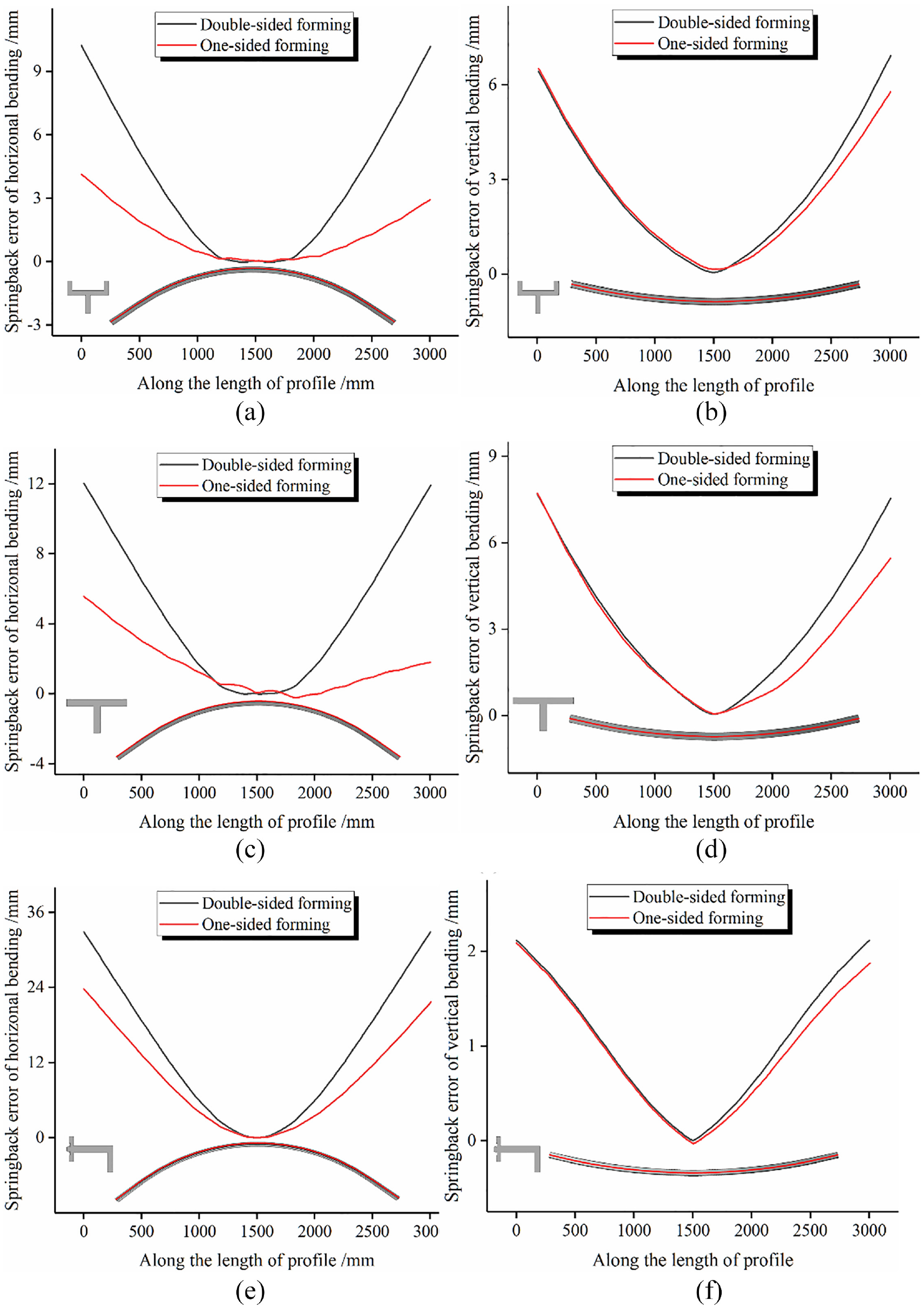
Springback error curve: (a) horizontal bending springback error of Y-profile, (b) vertical bending springback error ofY-profile, (c) horizontal bending springback error of T-profile, (d) vertical bending springback error of T-profile, (e) horizontal bending springback error of L-profile, and (f) vertical bending springback error of L-profile.
It can be seen from Figure 8(b), (d), and (f) that the vertical bending springback error of the profiles processed by one-sided forming and double-sided forming are basically the same in the section of 0–1500 mm. In the section of 1500–3000 mm, the vertical bending springback error of one-sided forming are smaller than that of double-sided forming. The reason of this phenomenon is the same as that of horizontal bending springback error. Therefore, the application of one-sided forming is beneficial to reduce the springback error of workpiece.
Analysis of thickness
Figure 9(a) to (c) are the thickness variation curves of Y-profile, T-profile, and L-profile, respectively. It can be seen from Figure 9 that the thickness variation trends of the profiles processed by one-sided forming and double-sided forming are basically the same. Therefore, the two different movement tracks have almost no effect on the thickness change of workpiece. In particular, compared with the non-contact area of the profile and the dies, the thickness of the contact area is severely reduced. This is mainly due to the local stress concentration in the contact area between the profile and the dies, and the local plastic deformation in the thickness direction is serious. In addition, as a whole, the closer to the two ends of the profile, the more serious the thinning.
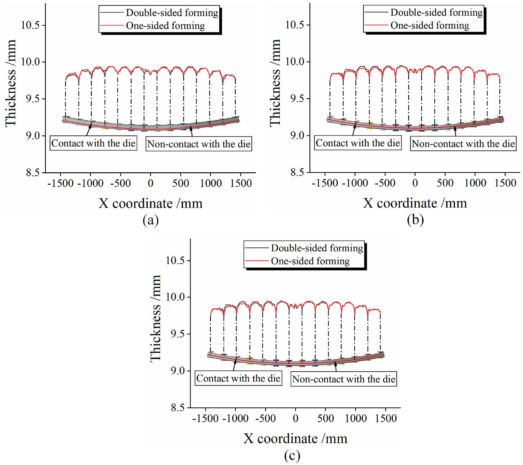
Thickness variation curve: (a) thickness variation of Y-profile, (b) thickness variation T-profile, and (c) thickness variation of L-profile.
Experimental verification
Experimental parts
Double-sided forming is a common clamp movement track, while one-sided forming is rarely used. Therefore, the FSB-MPRD forming equipment that had been researched and developed was used to carry out one-sided forming experiments in this paper. The L-profile, Y-profile, and T-profile were formed by one-sided forming, as shown in Figure 10. The material used in the experiment was AA6082 aluminum alloy. The profile length is 3000 mm, the horizontal bending radius is 2500 mm, and the vertical bending radius is 7000 mm. It could be seen from Figure 10 that the workpiece was well formed without obvious defects such as indentation, fracture, and cross-section distortion.
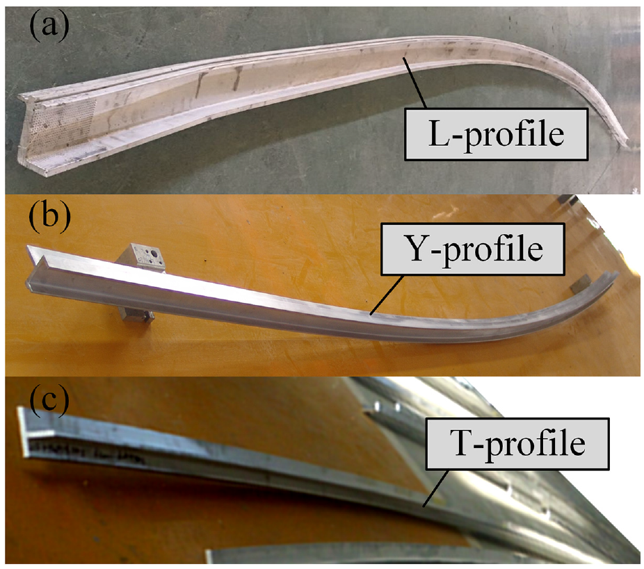
Experimental parts: (a) L-profile, (b) Y-profile, and (c) T-profile.
Analysis of experimental results
In order to verify the validity of the finite element model, the experimental parts were measured in terms of shape error, springback error, and thickness variation, and compared with the simulation results. Figure 11 shows the detailed statistics of shape error of profiles with different cross-sectional shapes formed by one-sided forming. It can be seen from Figure 11(a) and (b) that the maximum horizontal and vertical bending shape error measured by experiments are not significantly different from the simulated values. Due to the different cross-sectional shapes, the maximum value of the shape error is not exactly the same.
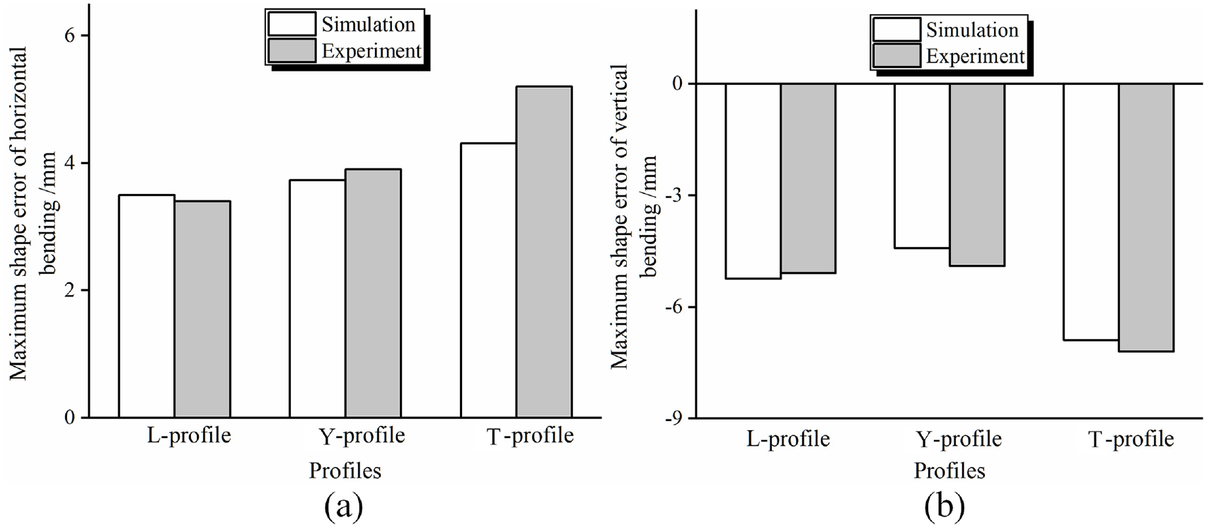
The shape error of different cross-section profiles formed by one-sided forming: (a) maximum shape error of horizontal bending and (b) maximum shape error of vertical bending.
In the forming process of FSB-MPRD, the maximum springback error occurs at both ends of the profile near the clamp. The springback error was measured using the springback detection equipment shown in Figure 2(b). Figure 12 shows the detailed statistics of the springback error of profiles with different cross-sectional shapes formed by one-sided forming. It can be seen from Figure 12(a) and (b) that the horizontal and vertical bending springback error measured by the experimental and simulation results are basically the same. And the cross-sectional shape of the profile is different, the maximum springback error is also very different.
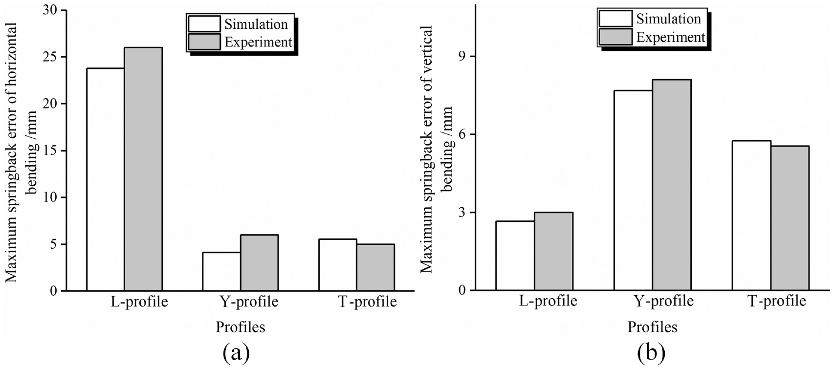
The springback error of different cross-section profiles formed by one-sided forming: (a) maximum springback error of horizontal bending and (b) maximum springback error of vertical bending.
To determine whether the thickness of the workpiece meets the product requirements is usually expressed by the thinning rate, as shown in the following equation:
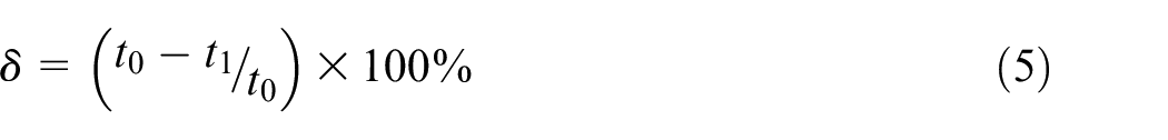
where t0 is the initial thickness of the workpiece and t1 is the thickness of the formed workpiece.
Figure 13 shows the detailed statistics of the thinning rate of different cross-section profiles formed by one-sided forming. The measurement path of the thinning rate is the same as the position in Figure 9. The thickness reduction of the contact area between the profile and the dies is more serious. Therefore, only the thickness change of the contact area is measured in experiments. It can be seen from Figure 13 that the simulation results are basically in agreement with the experimental results. And the thinning rate of simulation and experiment results are within the allowable error range of workpiece.
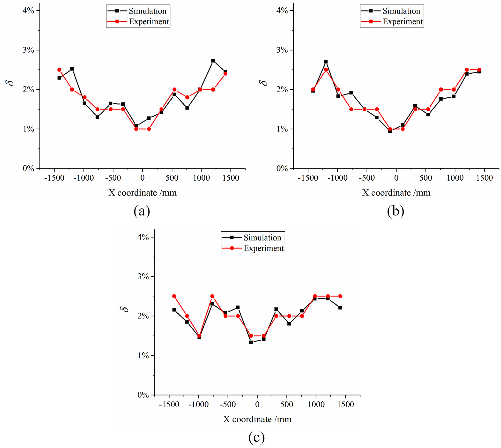
The thinning rate of different cross-section profiles formed by one-sided forming: (a) Y-profile, (b) T-profile, and(c) L-profile.
The main reason for the deviation between the simulation results and the experimental results is that the numerical simulation is carried out under ideal forming conditions, while the experiment is not. In experiments, there are obvious differences in temperature, blank material, and machine accuracy, which results in the shape accuracy, springback, and plastic deformation of workpiece slightly inconsistent with the simulation results. Therefore, the validity of the finite element model is verified through experiments. Numerical simulation can guide FSB-MPRD forming experiments.
Conclusion
The numerical simulation and forming experiments of Y-profile, T-profile, and L-profile are carried out by using two different movement tracks of clamp in this paper. Through the analysis of simulation and experimental results, the following conclusions could be drawn:
Compared with the double-sided forming method, the horizontal bending shape error of the workpiece processed by one-sided forming is smaller, but the vertical bending shape error is larger. Therefore, the movement track of the clamp has a great influence on the shape accuracy of workpiece.
The one-sided forming method makes the deformation of workpiece more uniform and increases the plastic deformation degree of profile. Compared with double-sided forming, one-sided forming can effectively reduce the springback error of workpiece.
The thickness variation trend of workpiece processed by one-sided forming and double-sided forming is basically the same. Therefore, the two different movement tracks of clamp have no effect on the thickness variation of workpiece. In particular, the two kinds of movement tracks of clamp can lead to large thinning of the contact area between the workpiece and the dies.
Footnotes
Author Contributions
Chuandong Chen conducted the numerical modeling and wrote the first draft of manuscript. Jicai Liang provided the concept. Yi Li conducted the experiments. Ce Liang edited the draft of manuscript.
Declaration of conflicting interests
The author(s) declared no potential conflicts of interest with respect to the research, authorship, and/or publication of this article.
Funding
The author(s) disclosed receipt of the following financial support for the research, authorship, and/or publication of this article: This work was financially supported by the Project of Jilin Provincial Scientific and Technological Department (20190302037GX); Project of Jilin Province Development and Reform Commission (2019C046-2).