
Abstract
Scheduling of the five-axis spline toolpath feedrate is of great significance for high-quality and high-efficiency machining using five-axis machine tools. Due to the fact that there exists nonlinear relationship between the Cartesian space of the cutting tool and the joint space of the five feed axes, it is a challenging task to schedule the five-axis feedrate under axial drive constraints. Most existing methods are researched for routine short spline toolpaths, however, the five-axis feedrate scheduling method expressed for long spline toolpaths is limited. This article proposes an interval adaptive feedrate scheduling method based on a dynamic moving look-ahead window, so as to generate smooth feedrate for long five-axis toolpath in a piecewise manner without using the integral toolpath geometry. First, the length of the look-ahead window which equals to that of the toolpath interval is determined in case of abrupt braking at the end of the toolpath. Then, the interval permissible tangential feed parameters in terms of the velocity, acceleration, and jerk are determined according to the axial drive constraints at each toolpath interval. At the same time, the end velocity of the current interval is obtained through looking ahead the next interval. Using the start and end velocities and the permissible feed parameters of each interval, the five-axis motion feedrate is scheduled via an interval adaptive manner. Thus, the feedrate scheduling task for long five-axis toolpath is partitioned into a series of extremely short toolpaths, which realizes the efficient scheduling of long spline toolpath feedrate. Experimental results on two representative five-axis spline toolpaths demonstrate the feasibility of the proposed approach, especially for long toolpaths.
Keywords
Introduction
Machining quality and efficiency are two key factors in manufacturing industry. Scheduling of the appropriate feedrate is acknowledged as one of the most important tasks in computer numerical control (CNC) machining to achieve favorable machining quality and efficiency.1–3 This is because of the fact that too low feedrate results in inefficiency feed motion, while too high feedrate may lead to the axial drive limitations being exceeded, which not only goes against the machining quality but also makes damage to the machine tools possibly. 4 One can schedule constant feedrate with initial launching and final braking for routine linear or circular toolpaths, while for free-form spline toolpaths, it is no longer suitable because the variable geometry within one spline toolpath requires different axial drive capabilities. 5 If a constant speed is utilized, the feedrate must be scheduled as a most conservative value so as to compromise to the most dangerous area on the spline. 6 Therefore, scheduling the feedrate adaptively becomes so significant that it has been researched in a lot of literatures.
Existing feedrate scheduling methods can be mainly classified into three kinds of categories in terms of the feedrate-sensitive point method, the constraint optimization method, and the feedrate-profile iterative adjustment method, respectively. The feedrate-sensitive point method searches dangerous corners with considered constraints, and connects the allowable speed values at these corners smoothly. For example, Yong and Narayanaswami 7 scheduled the feedrate-sensitive corners under limited chord-error, and connected the sensitive corners with acceleration constriants; Fan et al. 8 determined the permissible velocities of critical points with acceleration and jerk constraints, and connected them with a proposed jounce confined feedrate profile; Jia et al. 9 scheduled feedrate-sensitive regions under confined chord error, acceleration, jerk, and contour error, and connected these regions with the jerk-limited S-shape feedrate profile. This kind of method is mainly applicable to three-axis machine tools. While for five-axis machining with three translational axes and two rotary axes, the feedrate-sensitive point method cannot be directly utilized because of the nonlinear relationship between the tool motion and axial motion. 10
The second category of feedrate scheduling method, that is, the constraint optimization method, aims at solving the feedrate optimization problems with the objective of minimum path-tracking time under the considered constraints. For example, Debrouwere et al. 11 proposed a time-optimal path following method using sequential convex programming approach to solve the corresponding nonconvex optimal control problems introduced by the jerk limitation; Pham 12 established a velocity curve in the “displacement–velocity” phase space, and computed the time-optimal trajectory by integration; Erkorkmaz et al. 13 scheduled the feedrate for spline toolpaths by using a “pseudo-jerk” concept through linear programming; Liu et al. 14 linearized the interrelated multiple constraints and scheduled the optimal five-axis feedrate through linear programming. In addition, the third category of method, that is, the feedrate-profile iterative adjustment method, adjusts the feedrate profile iteratively until all of the considered constraints can be satisfied. For example, Sencer et al. 15 expressed the feedrate profile as a B-spline and modulated the control points iteratively to maximize the feed along the toolpath without violating the programmed feed and the axial drive limits; Beudaert et al. 16 discretized the toolpath and scheduled all discretization-point velocities by iteratively searching the deceleration point using dichotomy; Sun et al. 17 and Chen et al. 18 presented a proportional adjustment approach for the feed profile under axial jerk constraints, and afterwards, they further presented a moving knot sequence-based feedrate scheduling method under drive and contour-error constraints; 19 Liang et al. 20 expressed the feedrate in the form of B-spline curve, and adjusted it iteratively by raising the control points from a zero-speed velocity curve. It is worth noting that although above two categories of methods can be utilized for scheduling five-axis feedrate, most of them are merely suitable for short toolpaths because the integral iterative calculation should be fulfilled when using these approaches so that the computation load becomes too heavy to be employed for long toolpaths.
Based on above analyzation, one can see the fact that the feedrate scheduling methods for long five-axis toolpaths specifically remains challenging. To solve this issue, this article proposes a look-ahead-window-based interval adaptive feedrate scheduling method, so as to schedule the feedrate of five-axis long spline toolpaths in a piecewise manner. Due to the fact that scheduling the feedrate profile integrally requires high computational burden, this article partitions the long spline toolpath into intervals through applying the look-ahead window, and schedules near time-optimal feedrate profile within each interval with the consideration of smooth transition between adjacent intervals under axial drive constraints, thus piecewise generating the integral smooth feedrate profile. In the following texts, the detail scheme of the proposed method is given in section “Interval adaptive feedrate scheduling based on a look-ahead window,” and the performance of the proposed method is evaluated in section “Experimental tests.” Finally, conclusions are summarized in section “Conclusion.”
Interval adaptive feedrate scheduling based on a look-ahead window
Comparing with three-axis machine tools, the five-axis machine tools contain not only three translational axes, but also two additional rotary axes, which achieves more flexible spatial accessibility, but increases the difficulty of the feedrate scheduling for five-axis spline toolpath. It is a routine scheme to adjust the integral feedrate profile on the whole toolpath iteratively during five-axis feedrate scheduling, however, this is not suitable for long five-axis toolpath due to the time-consuming computational burden. In this article, the feedrate of the five-axis spline toolpath is scheduled interval by interval, and the transition smoothness is ensured through the applying of a look-ahead window. By doing this, the integral feedrate scheduling task for a long spline toolpath is divided into a series of successive feedrate scheduling tasks for extremely short toolpaths, so that the computational burden can be released.
The general idea of the presented interval adaptive feedrate scheduling method is introduced below. First, the length of the look-ahead window is determined according to the braking distance, and the length of each sub-divided interval is taken as the same value as the look-ahead window. Then, the allowable feed parameters in terms of maximum velocity, acceleration, and jerk of the current interval are determined according to axial drive constraints. After that, the feed parameters of the next interval are computed by applying the look-ahead window. Finally, schedule the current-interval feedrate based on S-shape acceleration/deceleration principle according to the starting velocity, the allowable feed parameters, and the ending velocity which is obtained using the next-interval allowable feed parameters. Note that during the final step of the proposed method, feedrate smoothness between two adjacent intervals are considered and ensured. The detail algorithm is described in the following sub-sections.
S-shape acceleration/deceleration principle
At the very beginning, the S-shape acceleration/deceleration principle which is also utilized by Ni et al., 21 is introduced briefly here because it is utilized in the subsequent feedrate scheduling procedures. A whole S-shape feedrate profile is illustrated in Figure 1, where vstart and vend means the start and end velocities, respectively; at,max and jt,max means the maximum tangential acceleration and jerk limitations; t1, t2, and t3 are calculated as
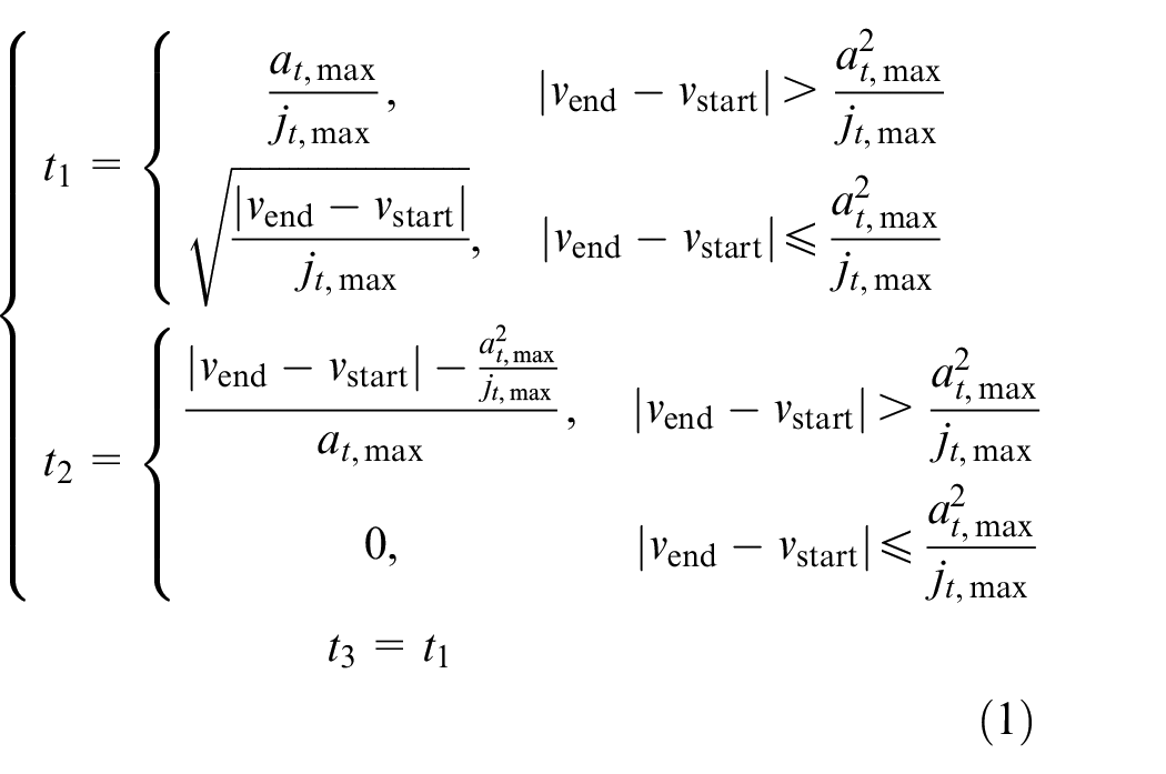
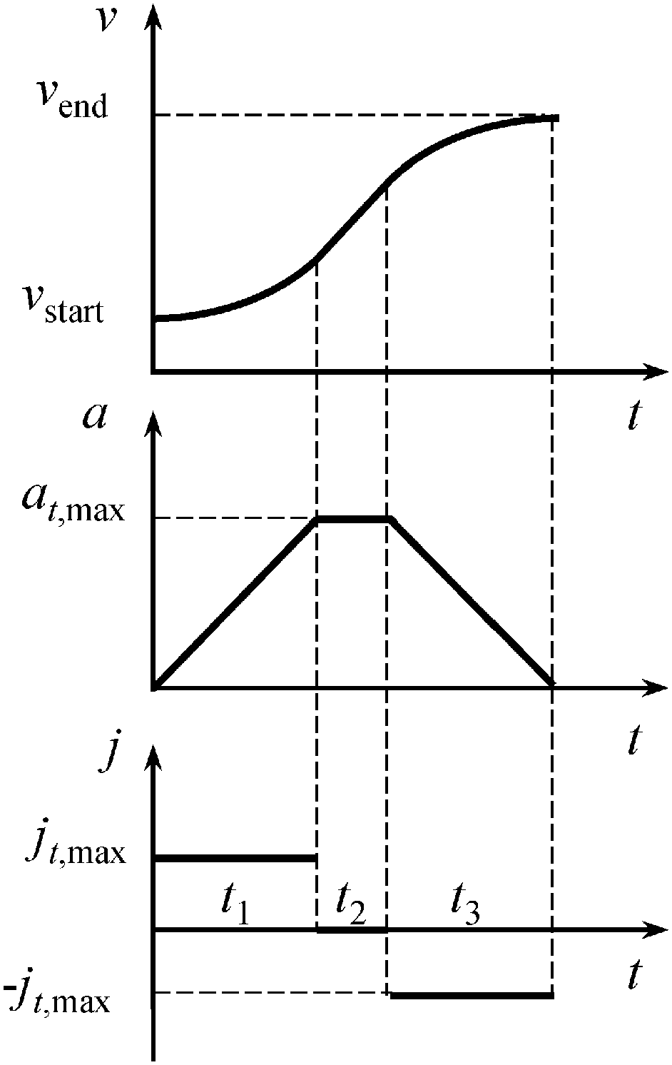
Illustration diagram of the S-shape feedrate profile.
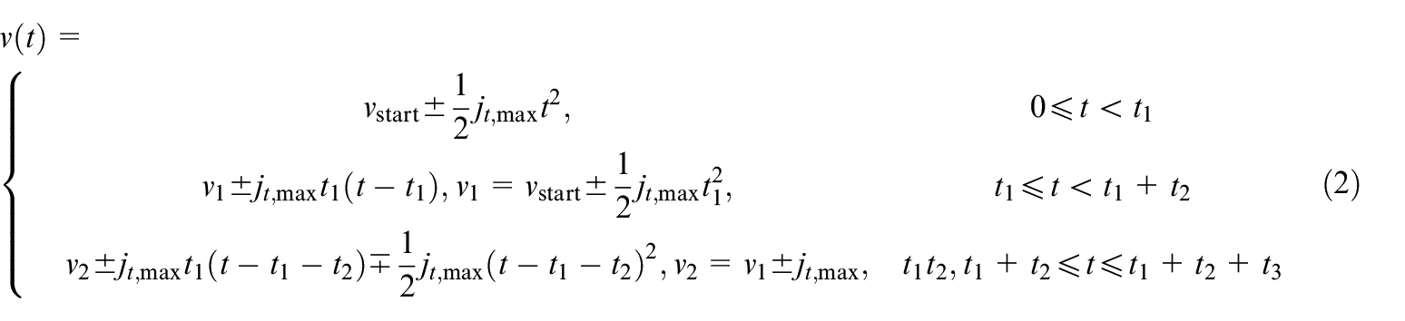
The velocity value v corresponding to time t under S-shape acceleration/deceleration principle can thus be computed by
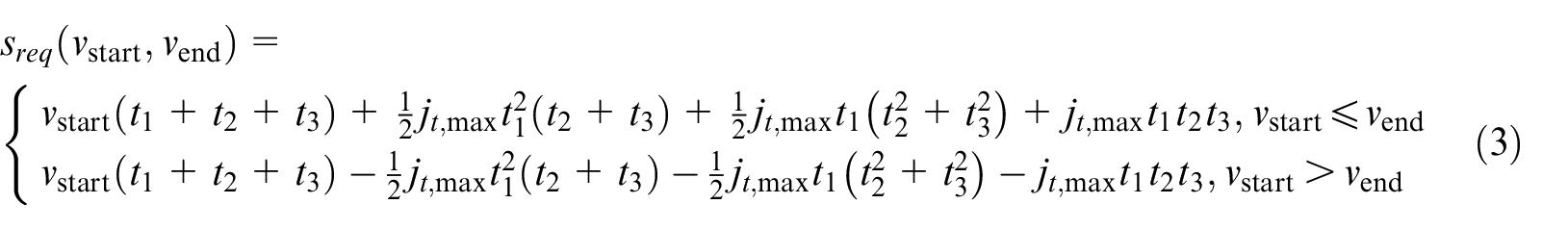
Accordingly, the required displacement of the acceleration/deceleration process from vstart to vend, denoted by sreq(vstart, vend), can be derived as
Determination of permissible feed parameters in each toolpath interval
The length of the toolpath interval, which equals to the look-ahead window length, should be determined first before calculation of the permissible feed parameters in each interval. Given a maximum programmed feedrate vmax, the braking distance, that is, the required displacement of the deceleration process from vmax to zero under the constraints of tangential acceleration and jerk limits, can be computed according to Equation (3) as
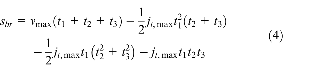
Once the look-ahead window length is not shorter than one braking distance, it will be not necessary to worry about whether there remains sufficient displacement for braking when we schedule the current-interval feedrate. On the contrary, the computational burden will be large if the length of the toolpath interval is too long. Therefore, the length of the toolpath interval and the look-ahead window, denoted by sw, is determined as one braking distance

The permissible feed parameters, that is, the maximum velocity, acceleration, and jerk under axial drive constraint, in each toolpath interval are calculated using the proportional adjustment method presented and used by Sun et al.
17
and Chen et al.
18
The specific procedure is given as follows. Denote
where
Given a scaling factor k, let vp, ap, and jp be
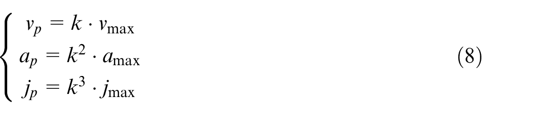
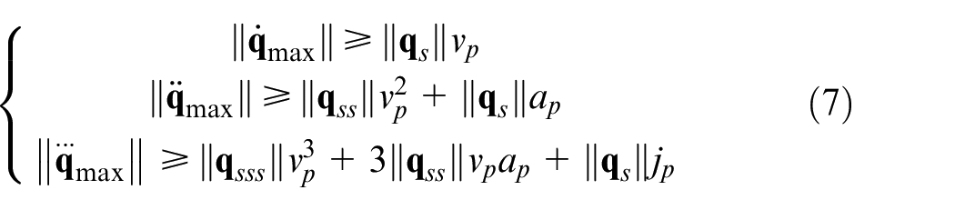
where vmax, amax, and jmax are the maximum programmed velocity, the maximum tangential acceleration, and the maximum tangential jerk, respectively. Substituting Equation (8) to Equation (7), the conditions that k should meet can be derived as
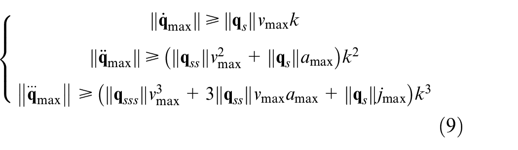
It is seen from Equation (8) that the scaling factor k should be scheduled as large as possible to increase the motion efficiency and the time optimality, however, k should not be higher than 1 because the maximum feed parameters must not be exceeded. In addition, it is seen from Equation (9) that the scaling factor k cannot be too large, in case of exceeding the physical drive constraints and the maximum programmed feed parameters. Therefore, the scaling factor k is calculated as the reachable highest value under the drive constraints, that is, k can be computed according to Equation (9) as

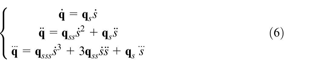
Given a five-axis toolpath with one tool-tip spline
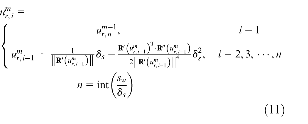
Above,
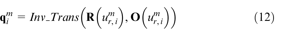
Thus, the derivatives of axial position
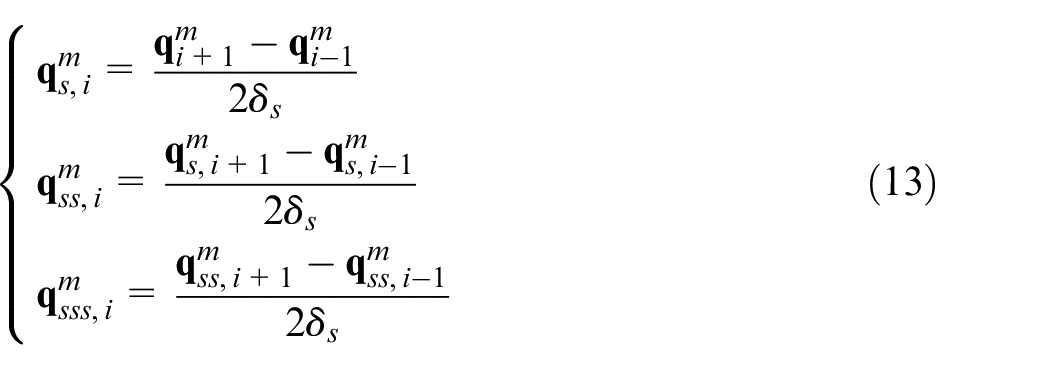
Substituting

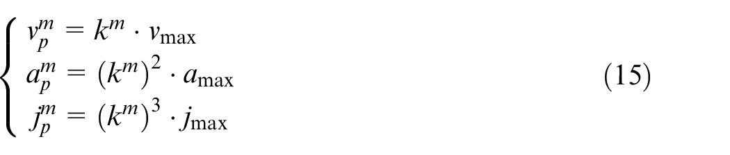
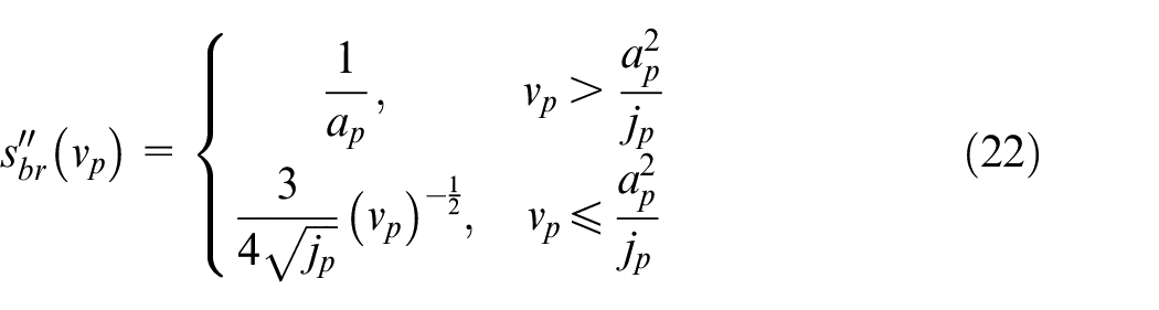
The permissible feed parameters of the mth toolpath interval, in terms of the maximum velocity
It is seen that the permissible acceleration and jerk may be much lower than their corresponding maximum limitations, which seems that the braking distance sbr computed by the maximum feed parameters in Equation (4) may not be sufficient for braking under the constraints of the decreased feed parameters. Therefore, we provide the following proposition to deal with this puzzle.
Proposition 1
The braking distance under S-shape acceleration/deceleration principle stays the same after scaling of the maximum feed parameters using Equation (8).
Proof
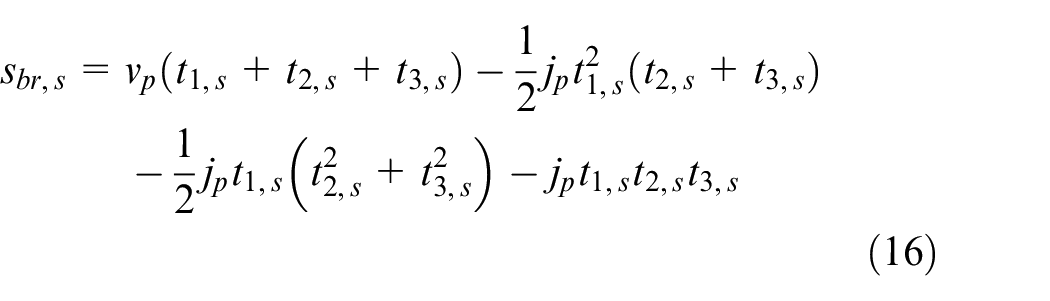
Denote the required braking distance after scaling of the feed parameters as sbr, s, and sbr, s can be computed according to Equation (3) as
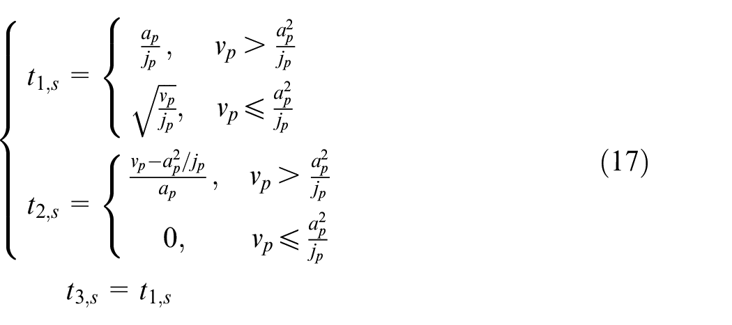
where t1,s, t2,s, and t3,s are increased, constant, and reduced acceleration times of the S-shape feedrate profile during braking from vp to zero after feed-parameter scaling, and they are computed according to Equation (1) as
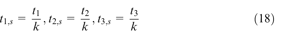
By substituting Equations (1) and (8) into Equation (17), we deduce the following conclusions
Furthermore, substitute Equations (18) and (8) into Equation (16), we obtain
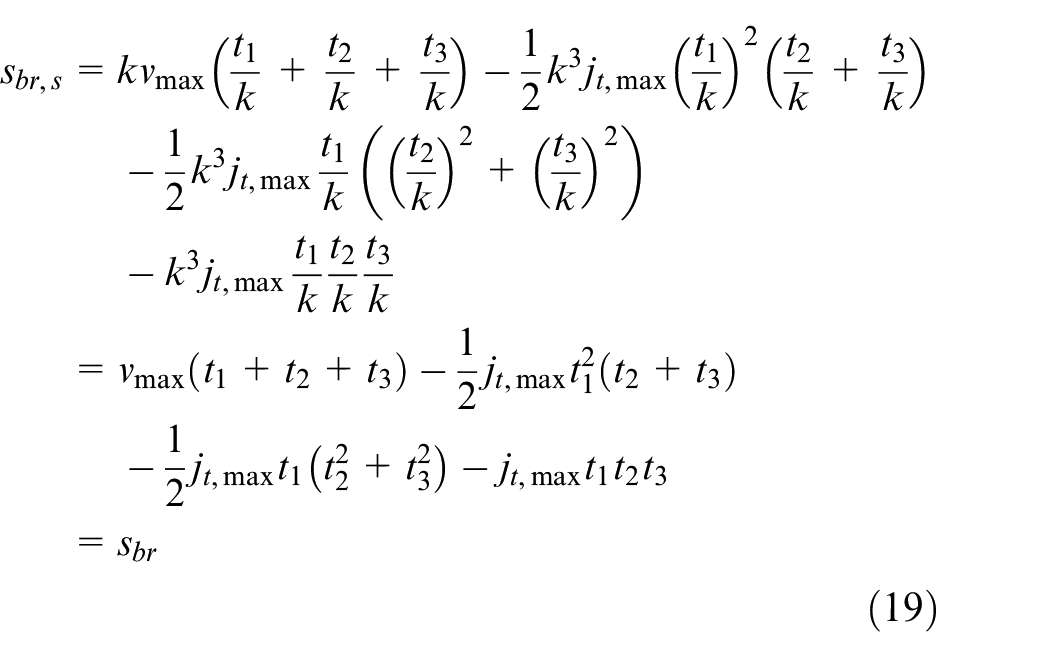
Equation (19) illustrates that the braking distance after feed-parameter scaling using Equation (8) equals to the braking distance before feed-parameter scaling, which demonstrates the Proposition 1.
Thanks to the correctness of Proposition 1, it is not necessary to adjust the length of toolpath interval and look-ahead window during the process of feedrate scheduling, which means that the look-ahead window length can be determined at once before the feedrate scheduling, and this is beneficial to the computation efficiency.
Scheduling of the interval adaptive feedrate
This sub-section schedules the feedrate for each toolpath interval based on the look-ahead window, according to the previously determined interval permissible feed parameters. First, the next interval of the toolpath is looked ahead to determine the ending velocity of the current interval. Then, the current interval feedrate is scheduled using S-shape acceleration/deceleration principle according to the start and end velocities, as well as the permissible feed parameters.
As shown in Figure 2, the next toolpath interval, that is, the (m + 1)th interval, is looked ahead by the rough interpolation and its permissible velocity
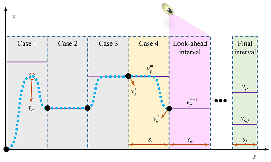
Schematic diagram of the look-ahead-window-based interval adaptive feedrate scheduling method.
Proposition 2
Denote the function of braking distance with respect to the braking velocity as sbr(vp), that is, denote the deceleration displacement from vp to zero under S-shape acceleration/deceleration principle as sbr(vp), thus sbr(vp) is a convex function.
Proof
By letting vstart = vp, vend = 0, at,max = ap, jt,max = jp, and substituting them to Equation (1), we get
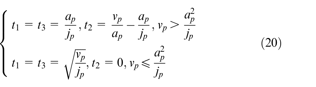
Substituting Equation (20) to Equation (3), we can derive the braking distance sbr(vp) as
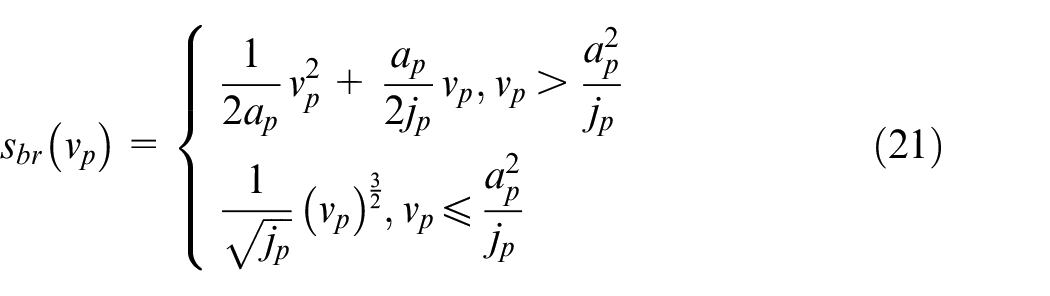
The second-order derivative of sbr(vp) with respect to vp is thus obtained
Therefore, it always has
Given a scaling factor kf < 1, the following Equation (23) is always satisfied due to the fact that sbr(vp) is a convex function

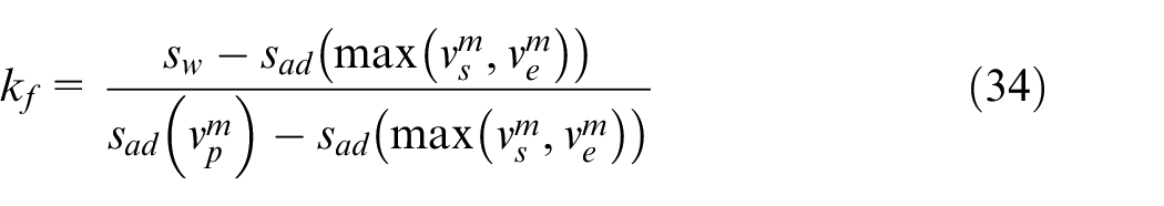
Take kf as
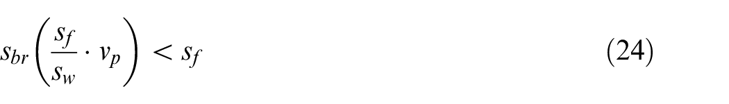
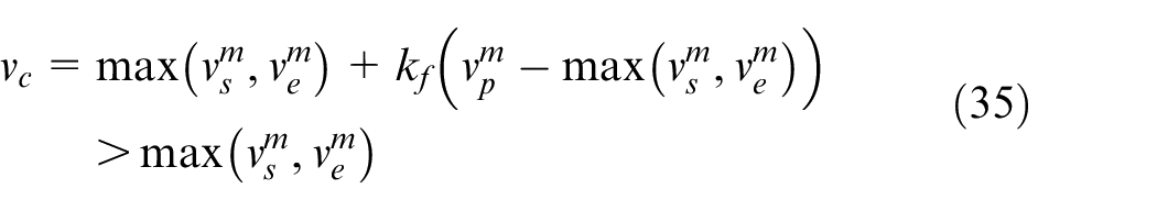
Equation (24) means that when we scale the permissible velocity vp to
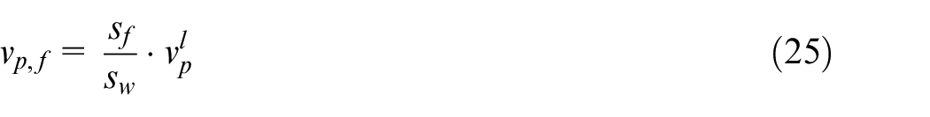
where l stands for the total interval amounts, and
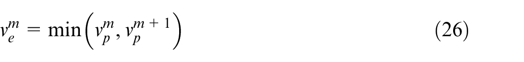
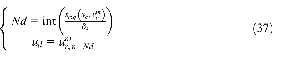
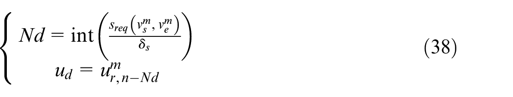
According to the next-interval permissible velocity, the end velocity of current interval
The start velocity of current interval
Case 1:
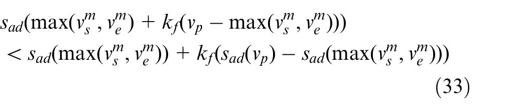
In this case, the permissible velocity is larger than either of the start and end velocities, therefore, the scheduled feedrate first increases from
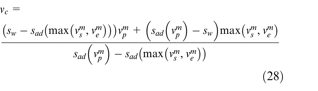
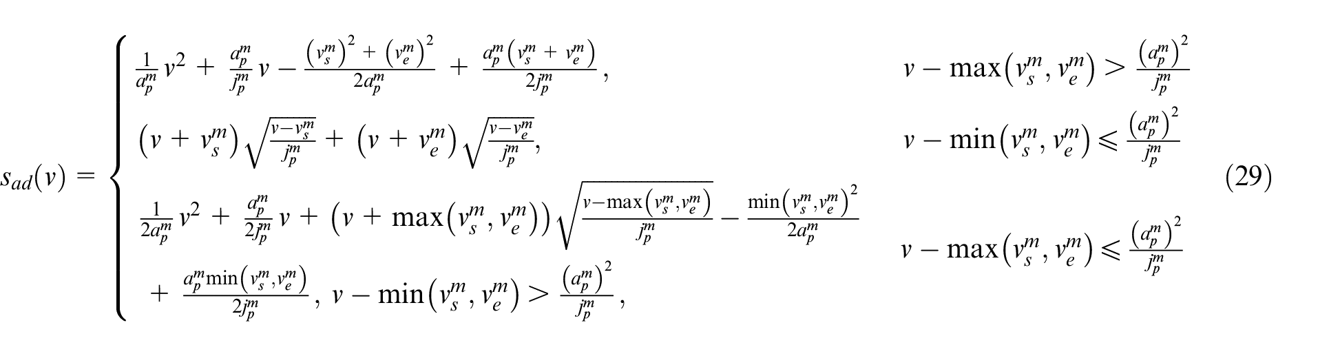
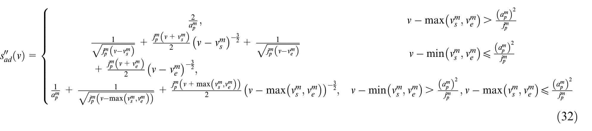
To determine vc, we define a displacement function sad(v) which represents the total required displacement of the processes including acceleration from

Compare the length of mth interval sw with
Proposition 3
When vc is selected as
Proof
According to Equations (1), (3), and (27), sad(v) can be rewritten as
Therefore, the first-order derivative of sad(v) with respect to v is
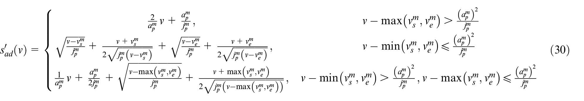
It is seen from Equation (30) that one always has
In addition, the second-order of sad(v) with respect to v is computed as
Therefore,
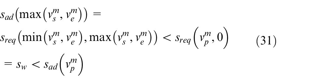
According to Equation (31), it is derived that
Thus, Equation (28) can be rewritten as
In addition, substitute Equations (28) and (34) to Equation (33) yields

Equations (35) and (36) demonstrate Proposition 3.
As a consequence, the current-interval maximum velocity vc is computed according to Equation (28) when
Furthermore, the acceleration-start point parameter is taken as the initial-point parameter of this interval, that is,
Case 2:
In this case, the permissible velocity equals to the start and end velocities of the current interval. Hence, constant speed is scheduled in this kind of interval as shown in Figure 2.
Case 3:
In this case, the permissible velocity equals to the end velocity which is larger than the start velocity. Therefore, the acceleration from
Case 4:
In this case, the permissible velocity equals to the start velocity which is larger than the end velocity. Therefore, the deceleration from
Above four cases can cover all situations possible to occur, and the reason is analyzed as follows. On one hand, it is seen from Equation (26) that we always have
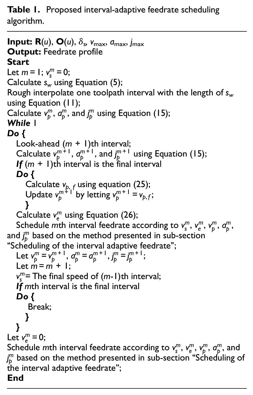
Based on above analyzation, the main procedure of the presented interval-adaptive feedrate scheduling method for long five-axis spline toolpath is summarized as the pseudocode in Table 1. First, execute the rough interpolation of one toolpath interval, and calculate the permissible feed parameters of the current interval. Then, look-ahead the next interval, and calculate the end velocity of the current interval. After that, schedule the current-interval feedrate according to the corresponding case in sub-section “Scheduling of the interval adaptive feedrate.” Finally, determine whether the final interval is reached, and end the algorithm once the final interval feedrate has been scheduled. The whole procedure can be executed without computation-time unfixed iterations, and only one small interval feedrate is scheduled in each period no matter how long the toolpath is, which is favorable to the efficient scheduling for the feedrate of long five-axis toolpaths.
Proposed interval-adaptive feedrate scheduling algorithm.
Experimental tests
In this section, experiments are conducted to evaluate the performance of the presented feedrate scheduling method, including the tests for both short and long toolpaths.
Experimental setup
A five-axis feed-drive experimental platform with three translational axes x, y, and z and two rotary axes B and C as shown in Figure 3 is developed in-house for the experiment tests. The three translational axes x, y, and z are driven by three ASDA® servo motors, and their leads are all 4 mm. The two rotary axes B and C are driven by two ASDA® servo motors, and their reduction ratio are all 90. The five servo motors run in velocity mode, and the position loops of them are configured in an rapid control prototype (RCP) controller RT-Cube produced by Beijing Links® Corporation. The analog voltage commands from −10 V to + 10 V generated by the RT-Cube are utilized for control of the motors, and the 17-bit encoders embedded in the servo motors are utilized for position feedback. The direct and inverse kinematics of the five-axis feed-drive system with B and C rotary axes are provided in Equations (39) and (40), respectively
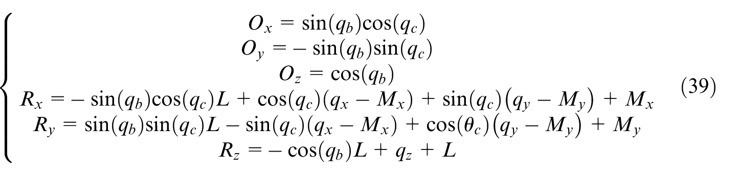
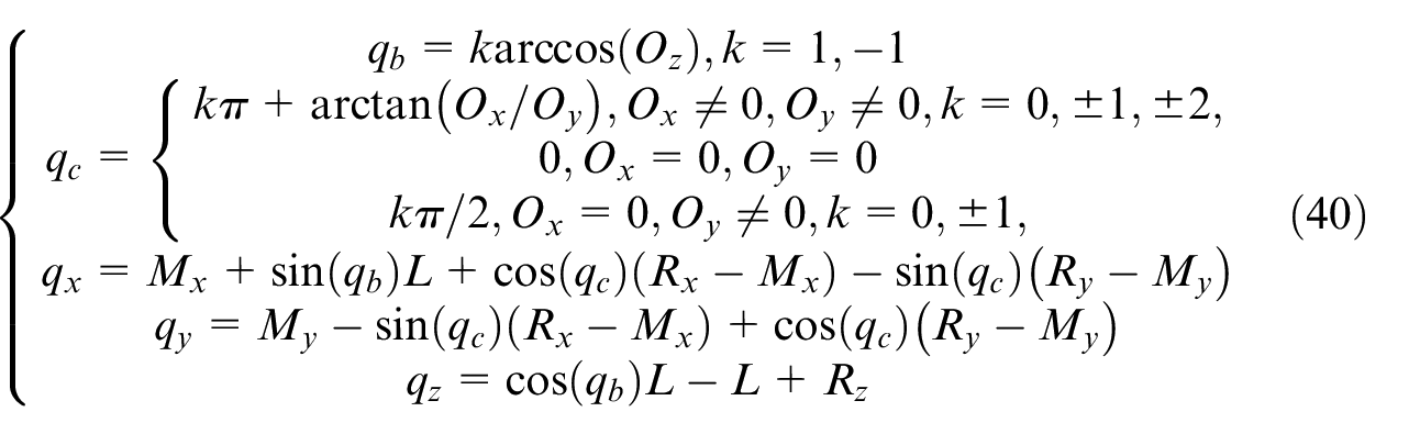
Above,
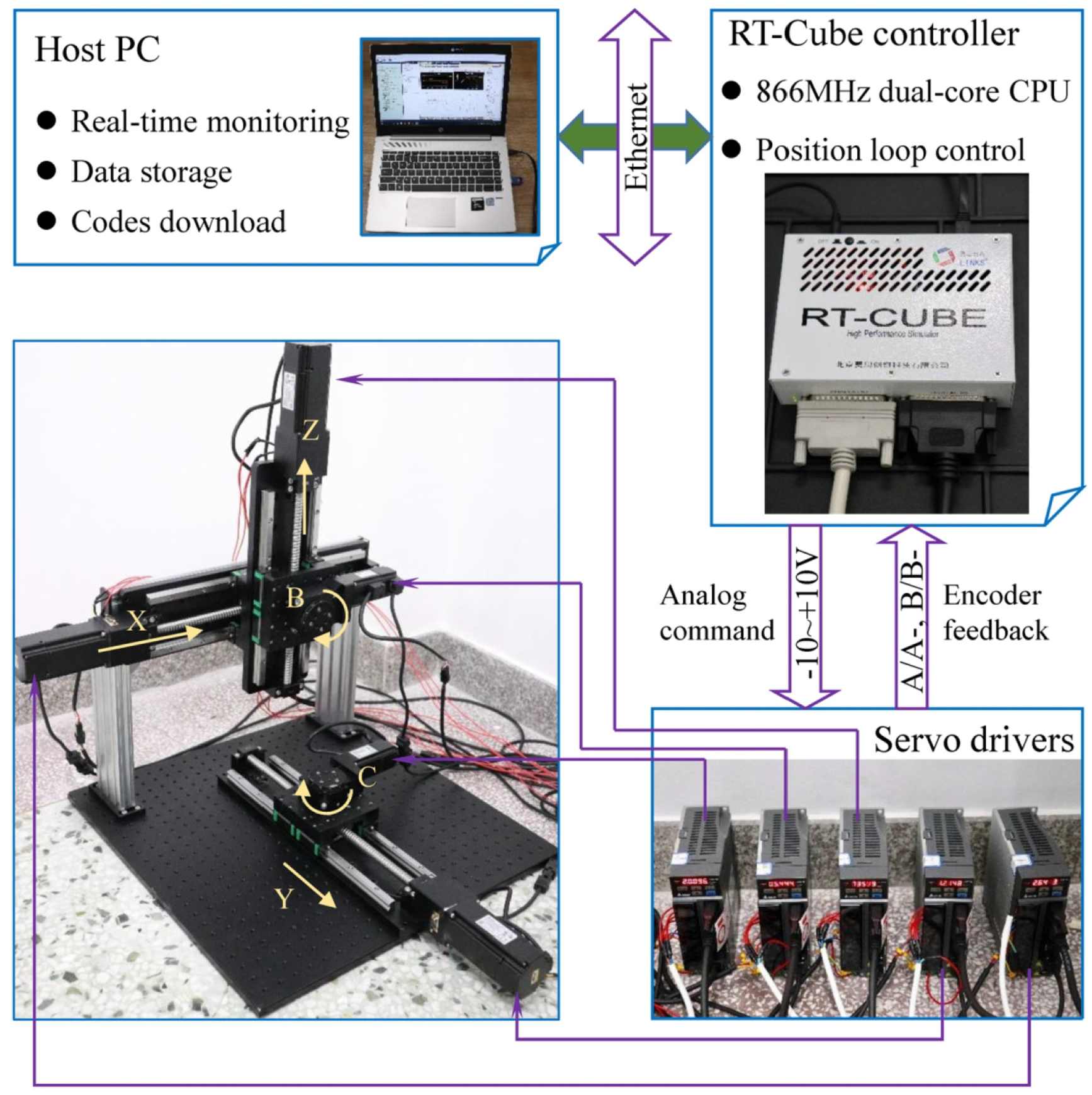
Experimental platform for the verification tests.
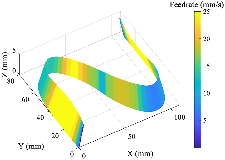
A short S-shape five-axis dual-NURBS toolpath shown in Figure 4(a) is first employed for testing the effectiveness of the presented feedrate scheduling approach. Furthermore, a long five-axis toolpath for the machining of the impeller shown in Figure 4(b) is employed for testing the performance of the presented method on long toolpaths. The impeller toolpath is generated by CAM software NX10.0 and the tool-axis direction is always perpendicular to the impeller surface.
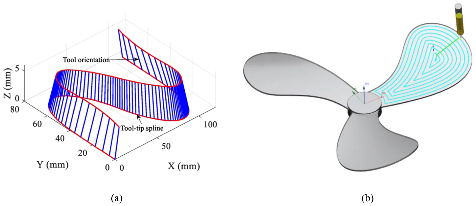
Five-axis toolpaths used for the experimental tests: (a) S-shape toolpath and (b) impeller toolpath.
Experimental results
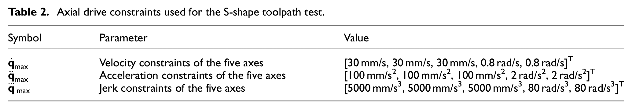
According to the drive capability of the utilized servo motors, the axial drive constraints utilized for the S-shape toolpath test are set as those in Table 2. The reference tool-tip velocity vmax is set as vmax = 25 mm/s. Accordingly, the maximum tool-tip motion acceleration and jerk are set as
Axial drive constraints used for the S-shape toolpath test.
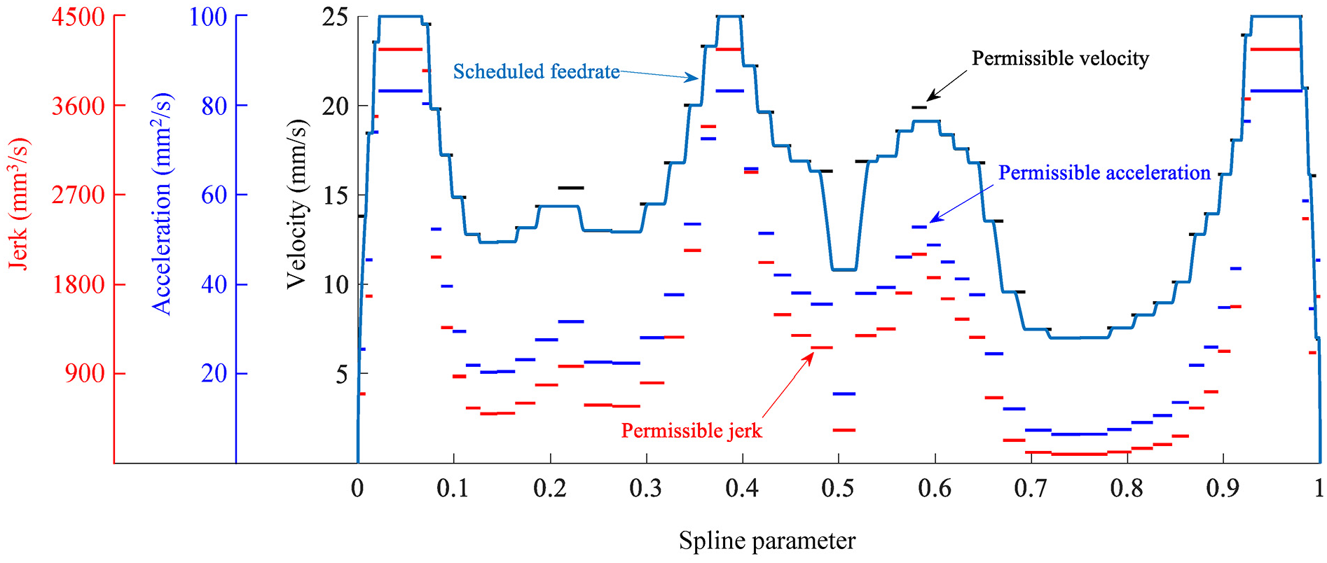
Feedrate scheduling result for the S-shape toolpath.
Scheduled feedrate on the S-shape five-axis toolpath.
The axial positions at each interpolation interval are computed according to the scheduled federate, with the interpolation period of 2 ms. The computed positions of five axes are used as position commands for control of the five-axis feed-drive systems in the Links® RT-cube controller. The real motion positions of five axes at each interpolation period are measured by the encoders embedded in the servo motors, and the actual-position signals are collected by the RT-cube controller with a sampling period of 2 ms which is same to the interpolation period. The sampled position signals are then stored in the host PC. These positions of each axis are employed for calculation of the velocities, accelerations, and jerks of the five axes. The results are shown in Figure 7. As can be seen from Figure 7, the actual motion parameters of every axes can be effectively bonded within the constraints set in Table 2, and this demonstrates the feasibility of the presented interval adaptive feedrate scheduling method.
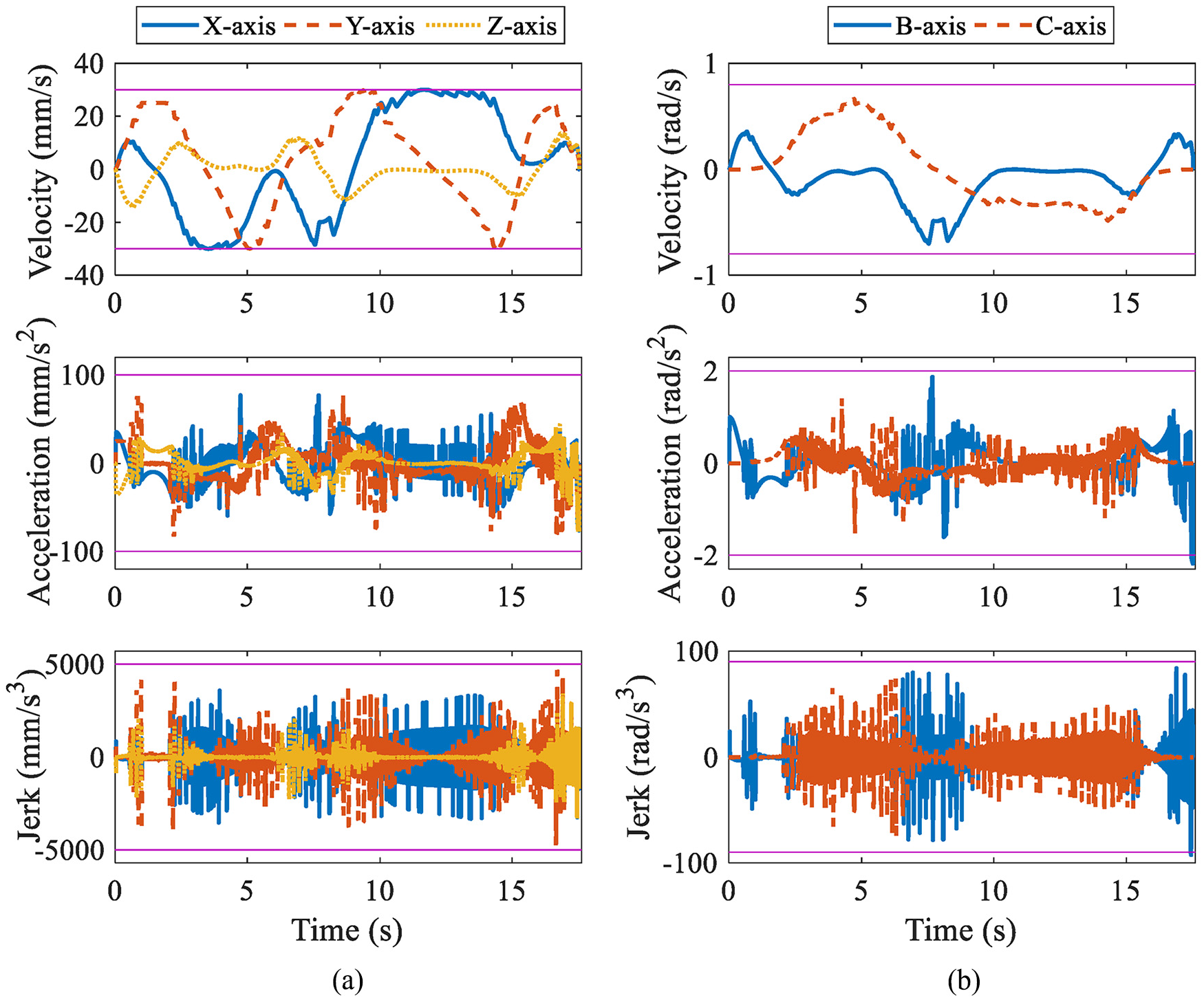
Experimental result of the S-shape toolpath: (a) actual feed parameters of translational axes and (b) actual feed parameters of rotary axes.
In addition, the proposed method is also compared with the recent published regional constant five-axis feedrate scheduling method by Ma et al. 22 Employing similar axial drive constraints provided in Table 2, the feedrate profile for the S-shape toolpath scheduled by Ma’s method is obtained, and it is compared with the feedrate scheduled by the proposed method in Figure 8. As shown in Figure 8, comparing with the regional constant feedrate the proposed interval adaptive feedrate varies more frequently, but more time-optimality can be obtained within the drive limitations. Besides, another advantage of the proposed method is that the interval adaptive method can generate feedrate profile for long five-axis toolpath in real time, because it schedules the feedrate interval by interval, unlike the previous regional constant method which schedule the feedrate by taking the whole toolpath in its entirety. The computation time for scheduling of the S-shape toolpath by Ma’s method is about 2.1 s on a 3.4-GHz Intel Core CPU. As for the proposed method, the feedrate scheduling is executed in a piecewise manner, and the computation time for each interval is about 0.027 s. Although the total computation time in 67 intervals is nearly the same with Ma’s method, the computation time within one single interval will not increases with the increasing of total toolpath length, while the computation time of Ma’s method scales with the toolpath length. This indicates that the proposed interval adaptive method is more suitable for real-time application during five-axis spline interpolation.
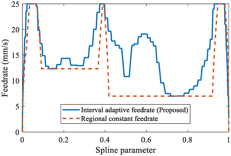
Comparison of feedrate profiles scheduled by the proposed method and Ma’s regional constant feedrate scheduling method.
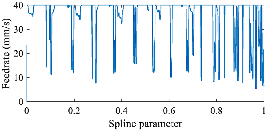
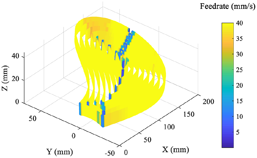
Furthermore, the impeller toolpath shown in Figure 4(b) is employed as the testing objective for evaluating the performance of the presented feedrate scheduling method on long five-axis toolpath. The axial drive constraints are tuned to those in Table 3 which are different to those in Table 2, so as to further evaluate the feasibility of the proposed approach. The total length of the tool-tip spline is about 2107.7 mm, and the length of toolpath interval is computed as 2.4 mm. Distinctly, schedule the feedrate on the integral toolpath which has a length of 2107.7 mm must be extremely time consuming, however, it is divided into a series of intervals with a length of 2.4 mm each interval so that the feedrate can be efficiently scheduled using the proposed interval adaptive method. The scheduled feedrate using the proposed method is shown in Figures 9 and 10. In addition, the actual motion parameters of the five axes are illustrated in Figure 11. Similar to the result of the S-shape toolpath, the actual velocities, accelerations, and jerks of five axes of the impeller toolpath are all bonded within the limitations set in Table 3. Hence, the effectiveness of the proposed feedrate scheduling method on long five-axis toolpath is verified.
Axial drive constraints used for the impeller toolpath test.
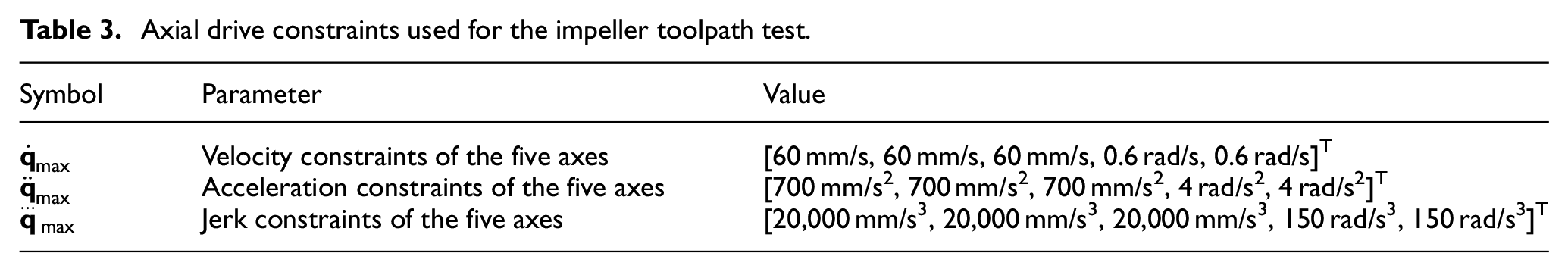
Feedrate scheduling result for the impeller toolpath.
Scheduled feedrate on the impeller toolpath.
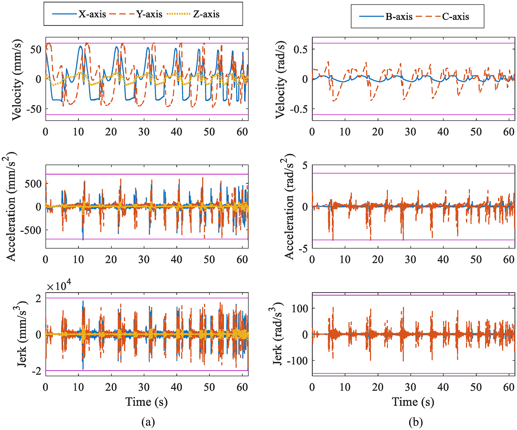
Experimental result of the impeller toolpath: (a) actual feed parameters of translational axes and (b) actual feed parameters of rotary axes.
Conclusion
This article presents an interval adaptive feedrate scheduling method based on a look-ahead window for long five-axis spline toolpaths. Using the proposed scheme, the feedrate of long five-axis toolpath can be scheduled in a piecewise manner, without requiring the integral geometric information of the whole toolpath. Therefore, the computational burden can be released, which means that the computation burden does not increase with the rising of the toolpath length. The key to the proposed approach is to schedule the interval start and end velocities and the interval permissible feed parameters in terms of tool-tip motion velocity, acceleration, and jerk, under the axial drive constraints and S-shape acceleration/deceleration principle. Once above parameters are obtained, the feedrate profile at each interval is scheduled as high as possible without increasing the computational burden under the permissible parameters, so as to generate integral near time-optimal feedrate. Experimental tests on two representative five-axis toolpaths, that is, a short S-shape toolpath and a long impeller machining toolpath, are conducted to evaluate the performance of the proposed method. Testing results illustrate that the presented interval adaptive feedrate scheduling method not only is feasible for both short and long toolpath, but also can make a good use of the axial drive capabilities. Contribution of this article is significant for CNC interpolation of long five-axis spline toolpaths. In future, the feedrate scheduling methods for multi-segment long five-axis spline toolpaths are under research.
Footnotes
Declaration of conflicting interests
The author(s) declared no potential conflicts of interest with respect to the research, authorship, and/or publication of this article.
Funding
The author(s) disclosed receipt of the following financial support for the research, authorship, and/or publication of this article: This research is supported by the Fundamental Research Funds for the Central Universities (3072020CF0701).