
Abstract
The acceleration/deceleration feedrate scheduling is one of the most important techniques in computer numerical control systems. Along with this technique, the bi-directional scanning technique is always employed. The bi-directional scanning technique consists of a backward scanning process followed by a forward scanning process. The two scanning processes in the conventional methods are executed in a serial manner by scanning through all the scheduling blocks one by one. Consequently, the feedrate scheduling will suffer from a heavy computational burden when there are massive blocks to be scanned, which deteriorates its real-time performance for computer numerical control machining. To alleviate the computational burden, a parallel acceleration/deceleration feedrate scheduling approach is proposed in this article. With this method, the scheduling blocks are splitted into several scheduling units and the feedrate for each of them is scheduled simultaneously. The feasibility of the proposed approach is validated through the feedrate scheduling for two widely used butterfly and helix paths. For a constructed example of feedrate scheduling, a significant acceleration ratio about 3.7 on a personal computer with a quad-core central processing unit is achieved.
Keywords
Introduction
In order to meet the high-speed and high-accuracy requirements in modern computer numerical control (CNC) equipment, various techniques have been proposed to schedule the feedrate for CNC machine tools. Due to its robustness and high computational efficiency, the acceleration/deceleration (AD) feedrate scheduling method is one of the most widely used scheduling methods in CNC systems.
The AD method was first applied to plan motions for single-axis systems and linear tool paths1–4 and extended to deal with motions for parametric tool paths later.5–12 As mentioned in previous studies,13–17 the most widely used profiles in AD approach are polynomial (e.g. linear-velocity, trapezoidal-velocity and trapezoidal-acceleration) and trigonometric profiles. The formulas of the AD feedrate profile are well studied, and one can easily construct an AD feedrate profile following the ideas in previous studies.2,10,12,15,18,19 However, the feedrate profile for the whole tool path usually consists of a sequence of AD feedrate profiles splitted by the so-called critical/break points. For multiple profiles, the start and end feedrates of each AD feedrate profile must be thoroughly handled to avoid feedrate discontinuity at the junction of two adjacent profiles. The bi-directional scanning technique, which consists of a backward scanning process followed by a forward scanning process, is normally adopted to guarantee the smoothness of the whole feedrate profile. Contrary to the construction of AD feedrate profiles, analysis of the bi-directional scanning technique is scarcely addressed. Bobrow et al. 20 proposed a switching-curve algorithm to solve the time-optimal control problem for manipulators. The algorithm, which was later adopted to plan time-optimal feedrate for machine tools,21–24 employed an idea similar to the bi-directional scanning technique and its feasibility was proved. However, the switching-curve algorithm differs from the bi-directional scanning technique in the following two aspects: (1) the backward scanning process was invoked several times in the switching-curve algorithm when multiple switching points are encountered, while it was employed only once in the bi-directional scanning technique; (2) the switching points were determined by solving differential equations in the switching-curve algorithm, while critical/break points were specified in advance for the bi-directional scanning technique. Luo et al. 14 introduced a doubly linked list to generate the feedrate profiles and the bi-directional scanning technique was applied within the list. Lee et al. 9 categorized the scheduling blocks into long and short block according to their length and applied a backward scanning process to the successive short blocks in priority. Zhao et al.11,17 detailed the bi-directional scanning technique and applied it within a look-ahead window in real time. To make the entire feedrate profile continuous, Fan et al. 10 proposed a backtracking algorithm which is similar to the bi-directional scanning technique.
To our knowledge, all of the conventional AD feedrate scheduling approaches applied the bi-directional scanning technique to scan through the entire scheduling blocks or the blocks in a look-ahead window (if a look-ahead window is involved) one by one. As mentioned in Suh et al., 1 thousands of blocks are pre-interpreted by the look-ahead algorithm in the commercial CNC systems. If the traditional serial approach is utilized, the feedrate scheduling for numerous blocks will become computationally demanding. Consequently, the real-time performance of the CNC systems will be deteriorated. To alleviate the heavy computational burden, a parallel AD feedrate approach based on the bi-directional scanning technique is proposed in this article.
The remainder of this article is organized as follows. In section “Feedrate-acceleration function,” the mathematical model of the feedrate-acceleration function is first established and then the properties of the feedrate-acceleration function are discussed. In section “Long-block threshold,” the long-block threshold is defined and the blocks are categorized into long and short blocks by their long-block thresholds. In section “Parallel feedrate scheduling approach,” a parallel approach for AD feedrate scheduling is proposed. Simulations are conducted in section “Examples” and conclusions are drawn in section “Conclusion.”
Feedrate-acceleration function
As discussed in Luo et al. 14 and Huang and Zhu, 15 there are seven practicable AD feedrate profiles, as shown in Figure 1. Given the kinematic constraints, the start velocity and the end velocity, the type of a feedrate profile is determined by its length. If the length is long, an acceleration (ACC)+constant feedrate (CF)+ deceleration (DEC) profile is adopted. If the length is short, an ACC or DEC profile is adopted. Otherwise, an ACC+DEC profile is adopted. The CF, ACC+CF or CF+DEC profile is utilized only under some rare conditions.
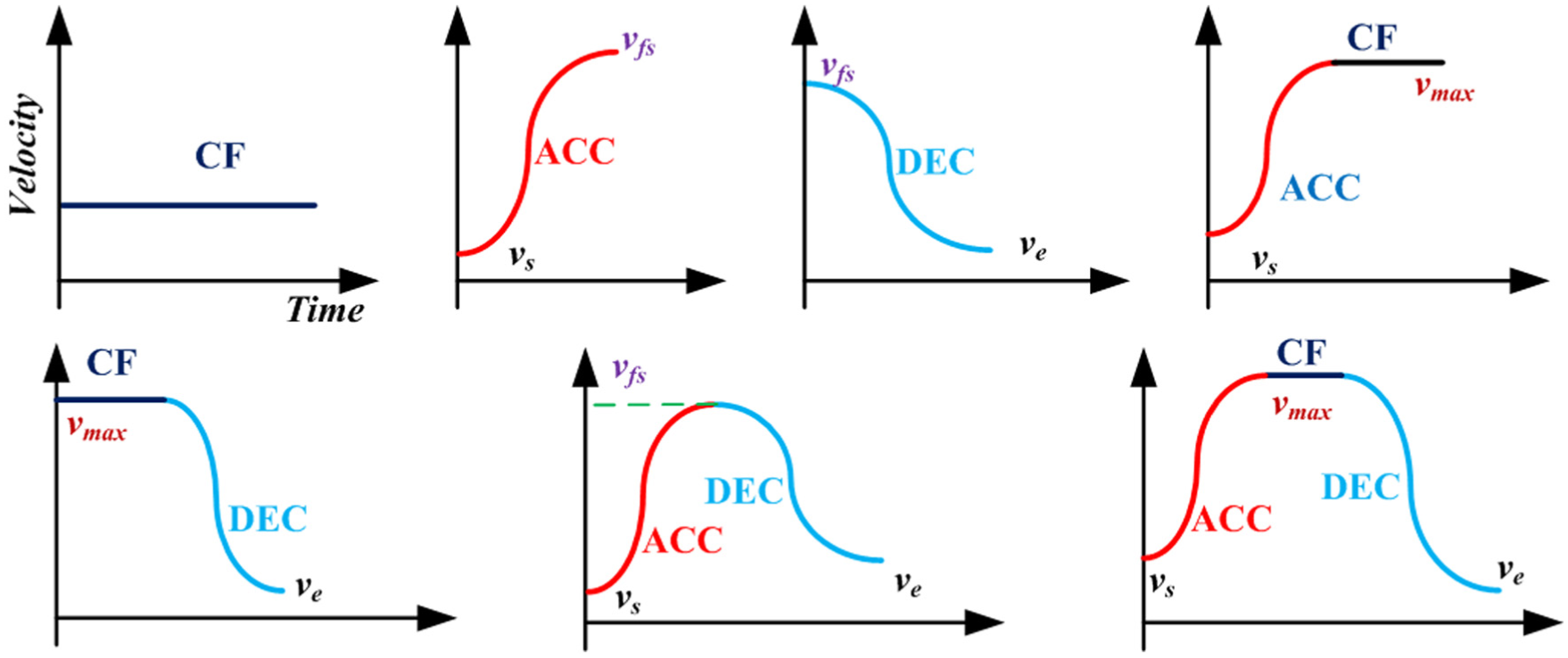
Seven practicable AD feedrate profiles.
For the ACC and DEC profiles, the boundary velocities will probably be decreased by the bi-directional scanning technique. 15 Specifically, the end velocity of the ACC profile is decreased, and so is the start velocity of the DEC profile. Therefore, it is necessary to study the properties of the ACC and DEC profiles with decreased boundary velocities. Note that the DEC profile can be regarded as an ACC profile accelerating the velocity from the end velocity to the start velocity, as shown in Figure 2. The properties of the ACC profile are explored first. The properties of the DEC profile can be obtained straightforwardly once the properties of the ACC profile are revealed.
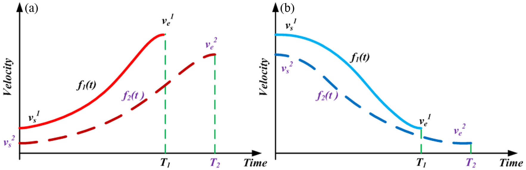
ACC and DEC profiles with decreased boundary velocities: (a) ACC profile and (b) DEC profile.
The function
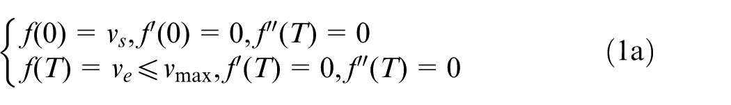
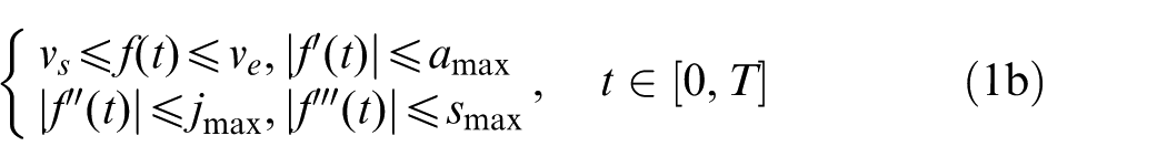
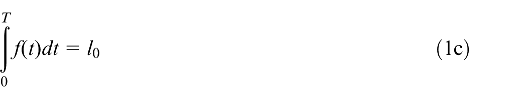
where t denotes time; T is the time required to traverse the path;
Given the kinematic constraints, a unique feedrate-acceleration function
Theorem 1
Suppose there is a feedrate-acceleration function
Proof
Denote
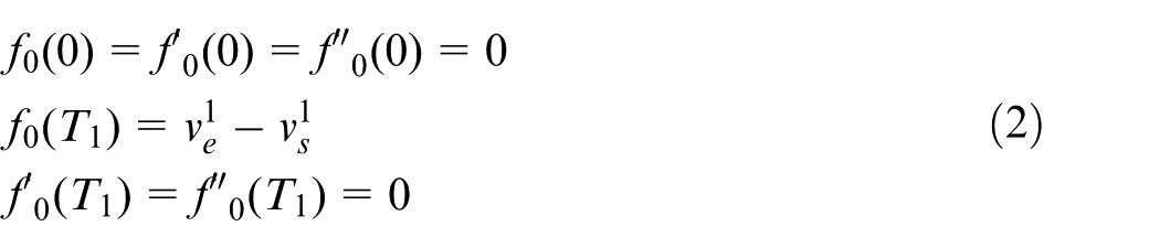
Then a function
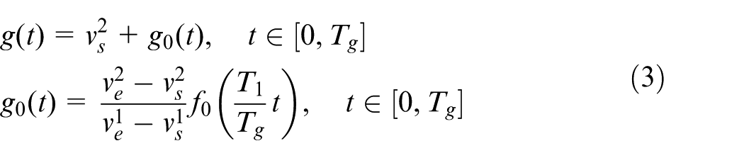
It is obvious that
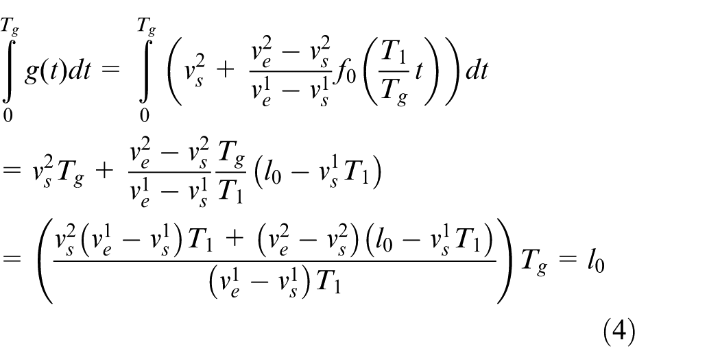
Because

According to equations (4) and (5), we deduce that
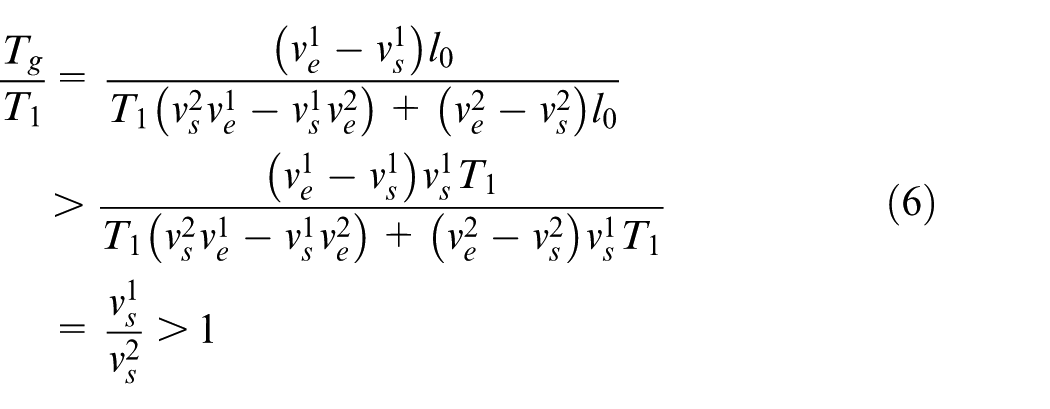
We also have
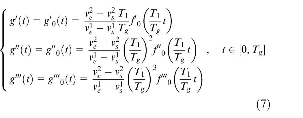
Based on equations (6) and (7), it can be deduced that there exists a function
Corollary 1
Suppose there exists a feedrate-acceleration function
However, the existence of a feedrate profile cannot be guaranteed by Theorem 1 if the start velocity is increased to a value in the interval
Long-block threshold
As mentioned in section “Feedrate-acceleration function,” a unique feedrate-acceleration function with a traveling distance d can be determined by the two boundary velocities

where
For the long blocks, we have the following theorem.
Theorem 2
For a long block, there always exists a feedrate profile transiting the velocity from any value
Without loss of generality, assuming that
By the definition of the long block, there always exists a feedrate-acceleration function transiting the velocity from any value
Based on Corollary 1, there exists a feedrate profile transiting the velocity from a value
Parallel feedrate scheduling approach
For a given tool path, the procedure for the AD feedrate scheduling consists of three stages: pre-processing, feedrate profile generation and interpolation stages. In the stage of pre-processing, the critical points are identified and the nominal velocity
In the stage of feedrate profile generation, the bi-directional scanning technique is utilized to smoothly connect the velocities for each block. The bi-directional scanning technique consists of a backward scanning process followed by a forward scanning process. The backward scanning process is carried out from the end to the start of the whole tool path. It attempts to find a feedrate-acceleration function to accelerate the velocity from the end to the start within each block. Therefore, the nominal start velocity of a block may be altered in the backward scanning process. The forward scanning process is carried out from the start to the end of the whole tool path. It attempts to find a feedrate-acceleration function to accelerate the velocity from the start to the end within each block. Therefore, the nominal end velocity of a block may be altered in the forward scanning process. After the bi-directional scanning, the final velocity
A pair of successive long blocks, as shown in Figure 3, is termed as a long-block duplet. A long-block duplet covers three boundary velocities, that is,
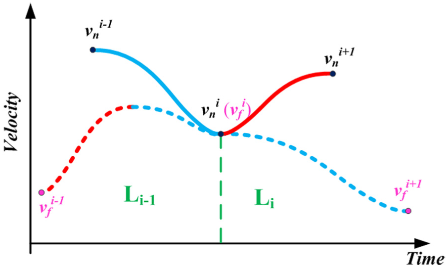
Long-block duplet and its boundary velocities.
Corollary 2
The middle velocity of a long-block duplet will remain unchanged after the bi-directional scanning, that is,
On the basis of Corollary 2, a parallel approach for feedrate scheduling is proposed. First, the blocks are categorized into long and short blocks according to the corresponding long-block thresholds. Then the overall blocks are splitted into several scheduling units by the middle of long-block duplet, as shown in Figure 4. The scheduling units are categorized into the following two types in terms of their compositions: type A—successive blocks ended by the middle of the long-block duplet and type B—the long block except the ones next to short blocks.
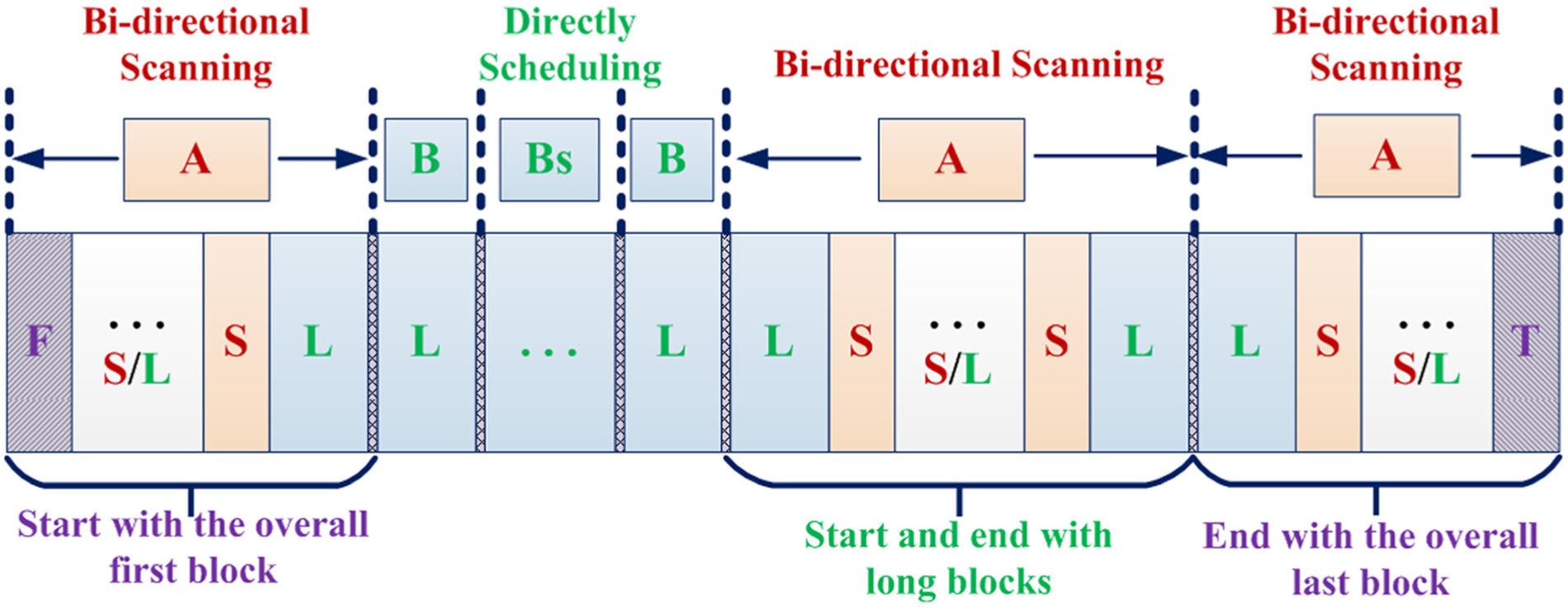
Illustration of spitting the feedrate scheduling blocks.
The first and last blocks of type A scheduling units are either long blocks or the overall first/last blocks, as shown in Figure 4. Note that the initial and final velocities of the tool path, that is, the start velocity of the first block and the end velocity of the last block, are normally zero and cannot be decreased. Therefore, the boundary velocities of type A scheduling unit will not be changed by the bi-directional scanning technique based on Corollary 2. Moreover, it is obvious that the boundary velocities of type B scheduling unit will also not be changed. Since the boundary velocities of all scheduling units remain unchanged, the feedrate for every scheduling unit can be scheduled separately and simultaneously. Specifically, the feedrates of the type A units can be scheduled by applying the bi-directional scanning technique to each unit, and the feedrates of the type B units can be scheduled directly with the nominal boundary velocities.
Examples
Calculation of the long-block threshold
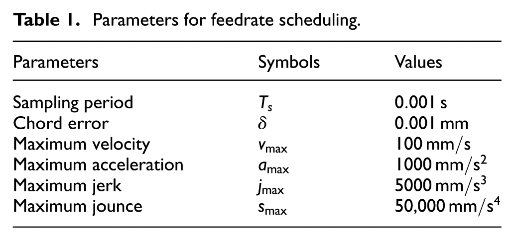
Since the long-block threshold plays a key role in the parallel feedrate scheduling, its calculation is discussed first. For a feedrate-acceleration function, the long-block threshold is determined by the end velocity, the kinematic constraints and the type of the feedrate profile. The kinematic constraints given in Table 1 will be adopted for all the examples in this article. Three typical feedrate-acceleration functions, that is, the jounce-confined polynomial function, the jerk-confined polynomial function and the sinusoidal-jerk trigonometric function, are considered.
Parameters for feedrate scheduling.
The long-block thresholds are obtained in advance by a straightforwardly search method. Given the end velocity
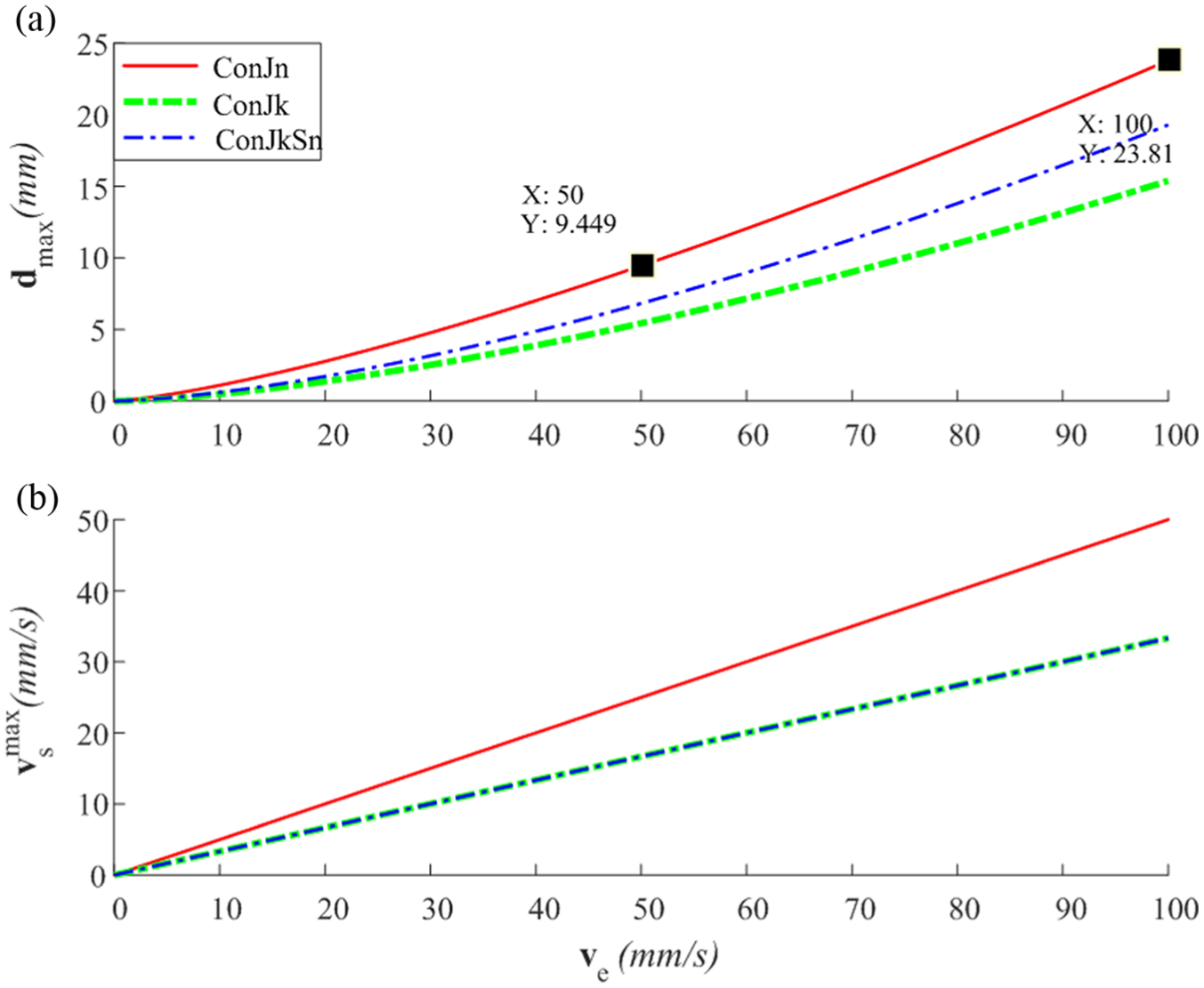
Long-block threshold with respect to end velocity: (a) the long-block threshold and (b) the start velocities at which the long-block thresholds are achieved.
The nominal end velocity of a block, which is set as the limit velocity at the critical point, is the same as the nominal start velocity of the next block. Since the long-block threshold is determined only by the higher boundary velocity, the long-block thresholds of two adjacent blocks may be identical. The repetitive calculation can be avoided in this situation.
Feedrate scheduling for a butterfly curve
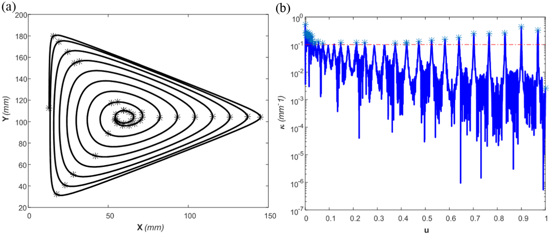
The butterfly curve as shown in Figure 6 is adopted to illustrate the feasibility of the proposed parallel approach. After the pre-processing, 29 critical points where the curvatures reach local maximum values are detected and the curve is thus splitted into 28 blocks. Meanwhile, the nominal velocity
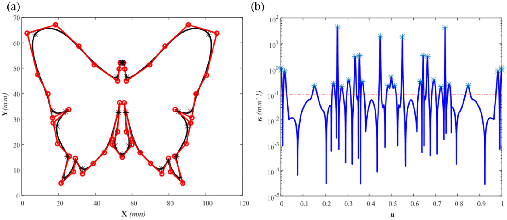
Butterfly curve and its curvature: (a) butterfly curve and (b) curvature of the butterfly curve.
In the feedrate profile generation stage, the conventional bi-directional scanning technique is applied to the entire 28 blocks, and we get the feedrate profiles as shown in Figure 7. The feedrate profiles are all continuous and the velocities, accelerations, jerks and jounces (if any) all satisfy the prescribed constraints.
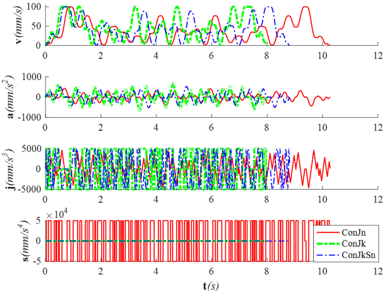
Feedrate profile for the butterfly curve.
For brevity, only the boundary velocities of the jounce-confined profile are given in Figure 8 to illustrate the feasibility of the parallel approach. The nominal velocities
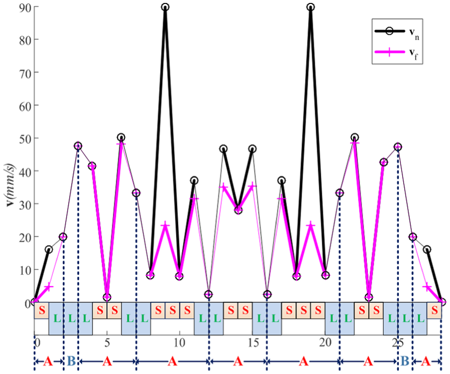
Boundary velocities before and after the bi-directional scanning.
Feedrate scheduling for a helix curve
To further illustrate the feasibility of the proposed parallel approach, a more complicated curve, a helix curve, is adopted. The curve and its curvature are depicted in Figure 9.
Helix curve and its curvature: (a) helix curve and (b) curvature of the helix curve.
The curve is splitted into 65 blocks by 66 critical points. The feedrate profiles are given in Figure 10 and the boundary velocities of the jounce-confined profile before and after the bi-directional scanning are given in Figure 11. Although there are 65 blocks for the helix curve, only 11 scheduling units, that is, three of type A and eight of type B, are identified due to the lack of long-block duplets, as shown in Figure 11. The boundary velocities of all the scheduling units keep unchanged in this case, which further demonstrates the feasibility of the proposed parallel approach.
Feedrate profile for the helix curve.
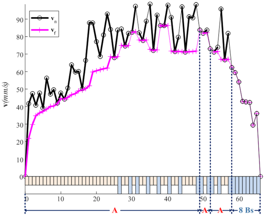
Boundary velocities before and after the bi-directional scanning.
Efficiency of the parallel approach
Considering that the butterfly and helix examples present several scheduling units of different types and have few scheduling blocks, it is difficult to compare the efficiency between the proposed parallel and the conventional serial approaches with the butterfly and helix examples. To illustrate the efficiency of the parallel approach, a simulation example which only concerns the jounce-confined feedrate profile generation is constructed. The blocks of the constructed example consists of the same number of successive short blocks separated by the long-block duplet, as shown in Figure 12. Due to the specified composition, the scheduling blocks can be explicitly splitted into several scheduling units of type A. Thus, the efficiency of the proposed and conventional methods can be faithfully compared. The boundary velocities are assigned as zero and
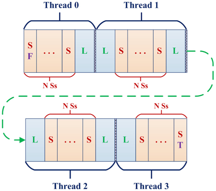
Constructed example to demonstrate the efficiency of the proposed approach.
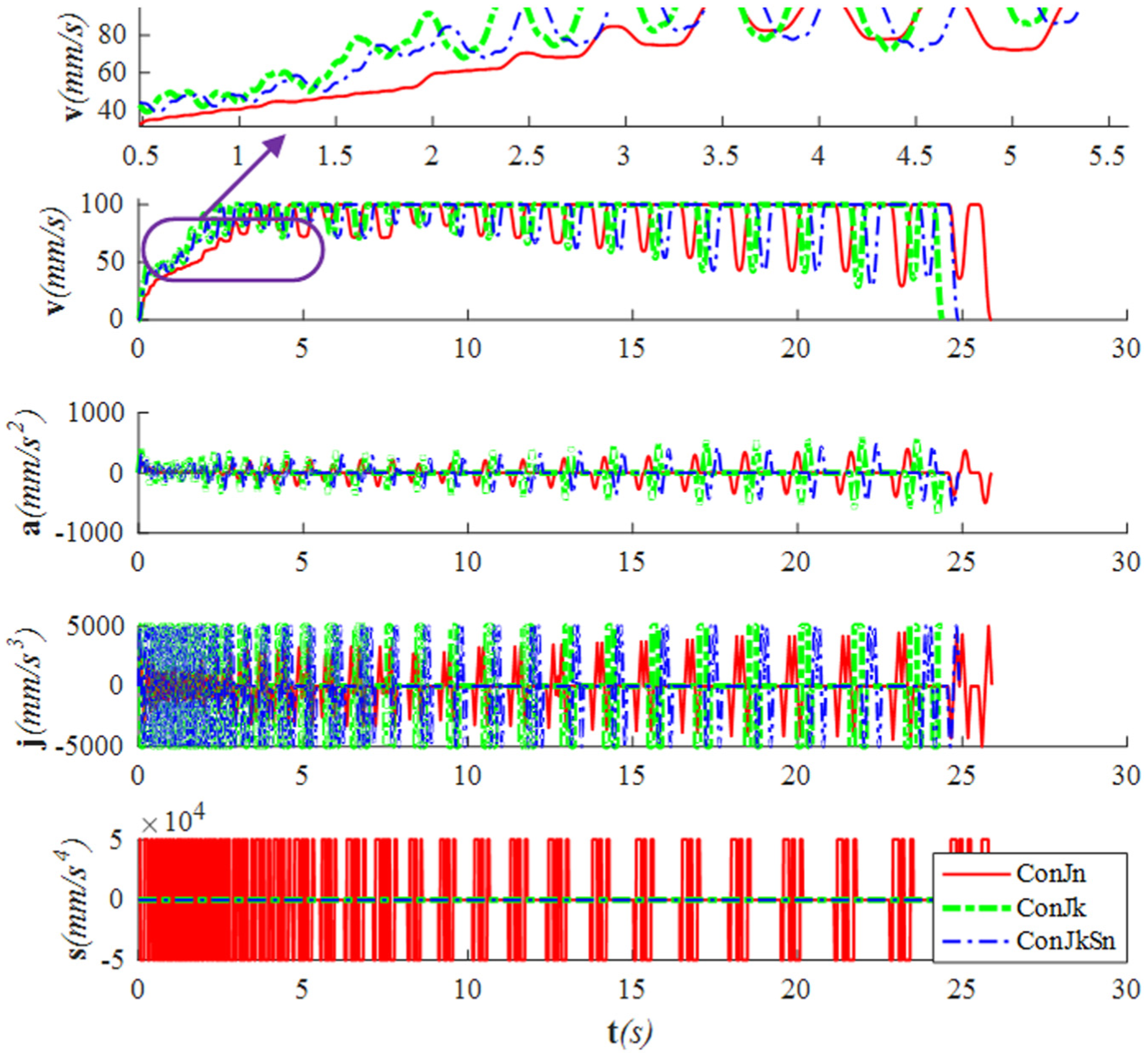
Since the simulation is implemented on a personal computer with a quad-core CPU (Intel® Core™ i5-3470 CPU, 3.20 GHz), three long-block duplets are used to split the blocks into four scheduling units of type A. Four threads (QThreads on Windows are used here. For more information, one may refer to http://wiki.qt.io/QThreads_general_usage) of which each one is responsible for a type A scheduling unit are invoked to realize the proposed parallel approach. The velocity profiles for the proposed parallel and the conventional serial approaches when the number of short blocks of one scheduling unit is 200 are given to show whether the implementation of the algorithms succeeds or not. The velocity profiles are both continuous and have exactly the same contour as illustrated in Figure 13, which implies a successful implementation of the algorithms. The time consumed for feedrate scheduling with respect to the number of short blocks of one scheduling unit is illustrated in Figure 14. The time consumed for the parallel and conventional serial approaches is obtained as the average time of 10 tests with the same simulation parameters. A near linear correlation is found between the computational time and the block number, and an acceleration ratio about 3.7 is achieved by the parallel approach. Considering only four cores are involved in this simulation, the acceleration is significant. In this sense, the proposed parallel approach can achieve a higher efficiency than the conventional methods.
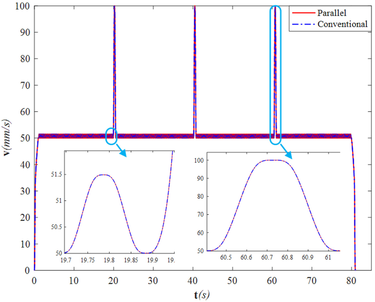
Velocity profiles for the constructed example when the number of short blocks is 200.
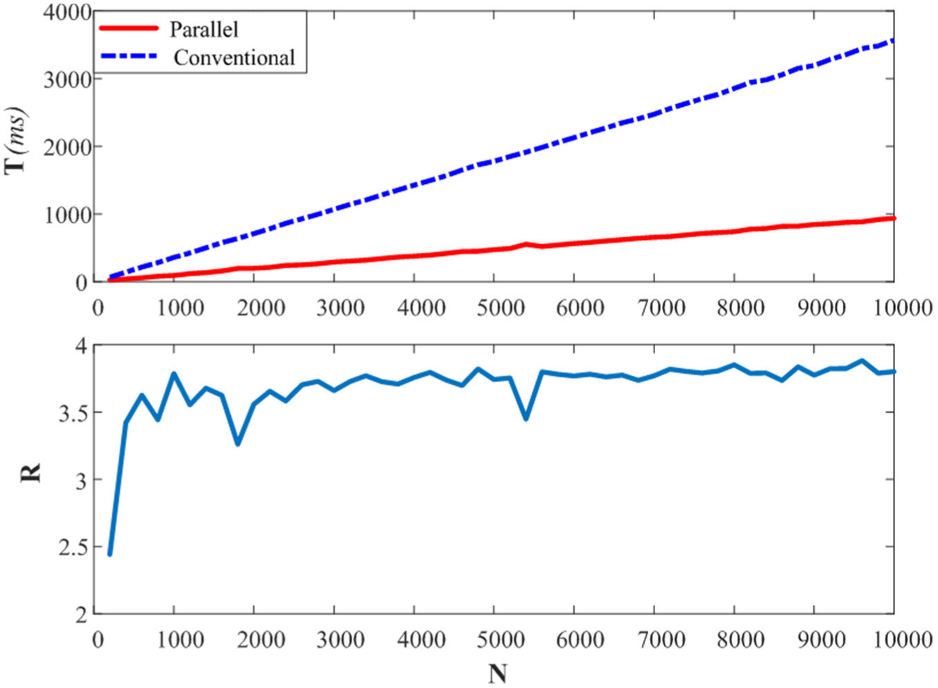
Consumed time of two approaches and acceleration ratio by the parallel approach.
Conclusion
This article presents a parallel AD feedrate scheduling approach for CNC machining based on the bi-directional scanning technique. The feasibility and high efficiency of the proposed method have been validated by simulations. To our best knowledge, this is the first attempt at introducing the parallel computation in the AD feedrate scheduling. The main contributions in this work are summarized as follows:
By analyzing the properties of the feedrate-acceleration function, the concept of the long block is introduced and it is found that the feedrate profile with deceased boundary velocities for the long block is always available.
Two types of scheduling units are defined. It is demonstrated that the boundary velocities of the scheduling unit keep unchanged in the feedrate scheduling.
By splitting the tool path blocks into scheduling units, a parallel AD feedrate scheduling approach is developed, with which the feedrate of every unit is scheduled simultaneously.
Footnotes
Acknowledgements
The authors wish to express deep gratitude to the editors for their thorough work of editing our manuscript.
Declaration of conflicting interests
The author(s) declared no potential conflicts of interest with respect to the research, authorship and/or publication of this article.
Funding
The author(s) disclosed receipt of the following financial support for the research, authorship, and/or publication of this article: This work was partially supported by the National Natural Science Foundation of China under Grant Nos. 51325502 and 91648202, and the Science & Technology Commission of Shanghai Municipality under Grant No. 15550722300.