
Abstract
This article presents effective algorithms to generate iso-parametric and iso-scallop tool path of five-axis computer numerically controlled machining for cyclide spline surfaces with flat-end cutters. Optimal tool orientations are generated by making the contact order between the cyclide patch and the cutter envelope surface as high as possible. Based on the optimal tool orientation, efficient methods are proposed to generate iso-scallop and iso-parametric tool paths for cyclide spline surfaces. Together with the existing methods of fitting arbitrary surface with cyclide splines, the proposed method can be used to improve five-axis machining efficiency of free-form surfaces.
Keywords
Introduction
Five-axis computer numerically controlled (CNC) machining has been widely used in the area of shipbuilding, aerospace, ceramics, automotive, and dies and mold industries. Because of the two additional rotational degrees of freedom, five-axis CNC machining offers clear advantages over three-axis machining, such as higher material-removal rates and improved surface finish. However, five-axis machining also suffers from problems such as large investment and more complex algorithms for cutter location (CL) data generation. The CL data generation problem is one of the basic problems in five-axis CNC machining.
Many CL data generation techniques have been developed in recent years to solve different problems in five-axis machining. Basically, the related studies can be classified into two groups: tool orientation design and tool-path generation. Both mainly aim at improving the machining efficiency and quality.
For tool orientation design, the simplest method is to use fixed tilt and yaw angles at a cutter contact (CC) point,1–3 which already improves the material cutting rate compared to three-axis machining. An improved method, called the principal axis method, always keeps the yaw angle equal to 0 and adjusts the tilt angle so that the minimum effective curvature of the tool is equal to the maximum effective curvature of the surface at the CC point.1,3,4 The above methods, although practical, clearly do not take the full advantage of five-axis machining. For non-ball-end cutters, it is possible to design optimal tool orientations to achieve second- or third-order contact.5–7 The tool orientations are also used to avoid collisions. In addition, dramatic changes in tool orientation from point to point may increase machining time 8 and decrease the machined quality. 9 As a result, lots of researchers focused on tool orientation smoothing.10–12
The methods of tool-path generation for five-axis machining can be divided into three categories: the iso-parametric machining, the iso-planar machining, and the iso-scallop height machining. The iso-parametric method keeps one of the two parameters fixed and the tool paths are generated along the other parametric curves of the surface. The iso-planar machining method establishes the tool paths by calculating the intersection curves of the machined surface and a group of parallel planes. These methods are very popular due to their simpleness. However, they are not optimal for most surfaces.
In five-axis CNC machining, one of the most significant criteria for the machining quality is the scallop height. After machining, a grinding operation is needed to smooth the machined surface if the surface quality is not adequate. However, the grinding operation applied to remove the scallop between adjacent tool paths is very expensive and time consuming. Therefore, an often used strategy is to set a tolerance bound for the scallop height. In general, it is hoped that tool paths of minimal length are generated with a given scallop tolerance bound. The most frequently used strategy to achieve this goal is the iso-scallop strategy, that is, the scallop height of any pair of corresponding points on adjacent tool paths is equal to the given scallop tolerance bound.13–16
Both the optimal tool orientation design and tool-path generation problems are quite involved in five-axis machining for the free-form surfaces. Most of the existed researches either approximated the designing surface as a sphere or approximated the effective cutting shape of the cutter as a circle locally, which might reduce the calculation time. However, the approximation error cannot be controlled. In this article, a new approach is adopted. For a given free-form surface, we first approximate the surface with a simpler surface, while this approximation error can be well controlled. Then we generate the tool paths for the new surface instead of the free-form surface. The simple surface under consideration is cyclide, which was first discovered by French mathematician and naval architect Dupin, and subsequently investigated by Maxwell, Casey, and Cayley. Recently, cyclide splines are used to model free-form surfaces in computer-aided design.17–21 The cyclide provides a nice model for CNC machining because its two families of iso-parametric curves are orthogonal circles.
This article presents effective methods to generate iso-parametric and iso-scallop tool paths for cyclide splines. Five-axis CNC machines with flat-end cutters are considered. The first step is to give conditions for second- and third-order contact between the cyclide surface and the cutter envelope surface, based on which an algorithm is given to generate optimal smooth tool orientations. By optimal, we mean the total contact order of the designed surface and the cutter envelope surface along the tool path is as high as possible. To achieve this, we only need to solve one optimization problem along a whole path while the existing methods need to solve one optimization problem at every CC point. Besides, the continuity of the tool orientations is also considered in our method. Based on the optimal tool orientation and properties of the cyclide patches, efficient and accurate methods are proposed to generate iso-parametric and iso-scallop tool paths for a given scallop tolerance bound. Based on the rotation model proposed in this article, there is no need either to approximate the effective cutting shape as a circle or to solve a complex system of equations to obtain the corresponding CC point. Combining existing methods on fitting arbitrary surfaces with cyclide splines,19–21 the method proposed in this article could be used for efficient tool-path generation of free-form surfaces. Numerical examples are used to validate the methods.
The rest of this article is organized as follows. In section “Preliminaries,” preliminaries about cyclides and five-axis machining are introduced. The optimal tool orientations are designed in section “Designing the optimal tool orientation.” The iso-parametric and iso-scallop tool-path generation methods for a single cyclide patch and cyclide splines are given in sections “Tool-path generation for a cyclide patch” and “Tool-path generation for a cyclide spline,” respectively. The simulation results of the proposed method are given in section “Example.” Finally, the article is concluded in section “Conclusion.”
Preliminaries
Basic properties about cyclide
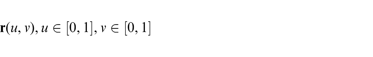
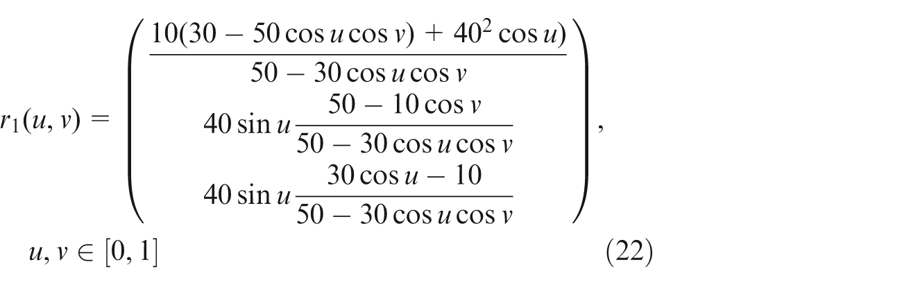
The cyclide can be defined as the envelope of a variable sphere having its center on a given plane and touching two given spheres. Each of the variable spheres contacts the envelope in a circle. The radii of these circles form a continuously varying function in one variable. The cyclide is a quartic surface which can be represented in both parametric and implicit forms. The parametric form of a cyclide patch, which we use extensively in this work, is shown in equation (1)
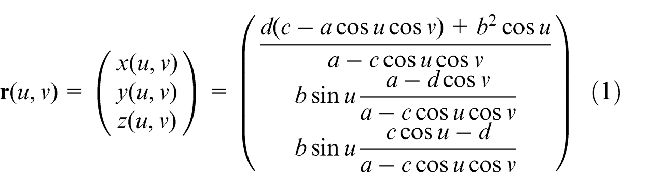
where u ∈ [0, 1], v ∈ [0, 1] and a, b, c, and d are constants satisfying b2 = a2 − c2.
There are many interesting properties about cyclide, some of which are related to this work and are listed below:
C1: the two families of curves of curvature are orthogonal to each other and are both circles.
C2: the curves of curvature mentioned in C1 are also iso-parametric curves and curves of principal curvature.
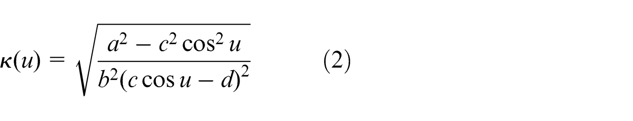
C3: the curvatures of the points on a curve of curvature form a continuous function in one variable which is denoted by κ(u) or κ(v).
We will show how to compute the curvature function of a curvature curve mentioned before, κ(u) or κ(v). For clarity, the procedure of calculating κ(u) is shown here, while κ(v) can be calculated in a similar way.
Given u = u0, u0 ∈ [0, 1], l(v) =
Five-axis CNC machining preliminaries
In this article, five-axis CNC machining with a flat-end cutter is considered, where the machining efficiency is effected by the tool orientation tremendously. The tool orientation can be represented in the local coordinate system XL , YL and ZL , as shown in Figure 1, which was reported in Lee. 22
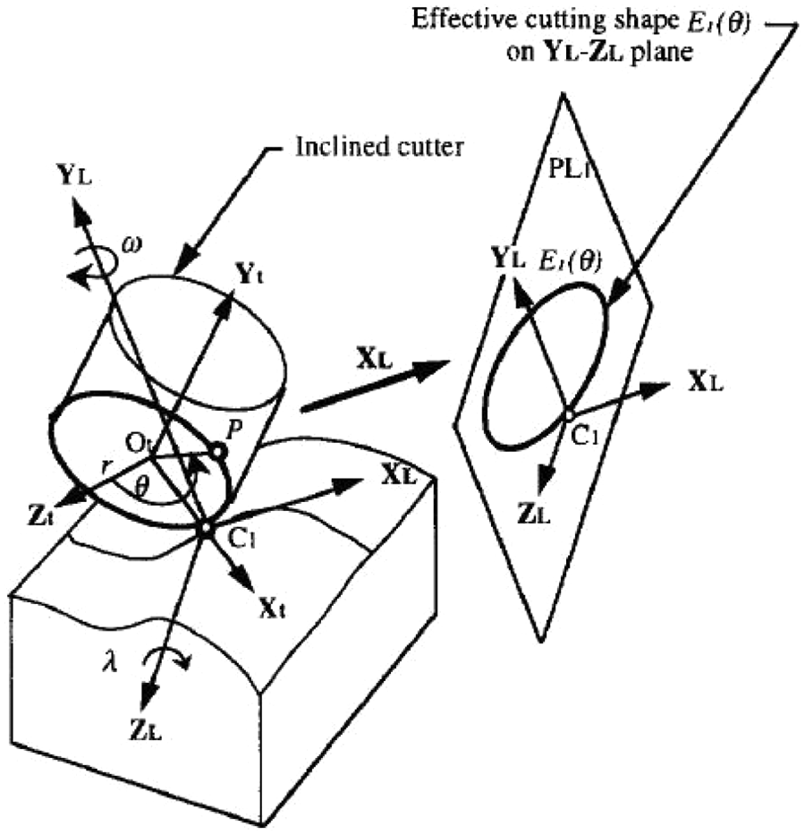
Flat-end cutter in local coordinate system.
The XL axis is lying in the current cutting direction and the YL axis is in the surface normal direction. The ZL axis is determined by the cross product of the XL and YL axes. The tilt angle λ is the angle the tool rotated about the ZL axis, and the yaw angle ω is the angle by which the tool rotated about the YL axis. Due to manufacturing requirements, λ and ω take values in the following ranges
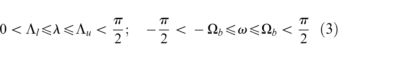
where Λ l , Λ u , Ω b are bounds determined by the CNC machine and other factors.
After λ and ω in the local coordinate system are given, the tool orientation
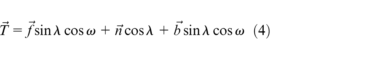
where
Let R be the radius and θ the parameter of the bottom circle of the cutter, as shown in Figure 1. Then, the bottom circle of the cutter can be described as the following parametric equation in θ in the XLYLZL coordinate system
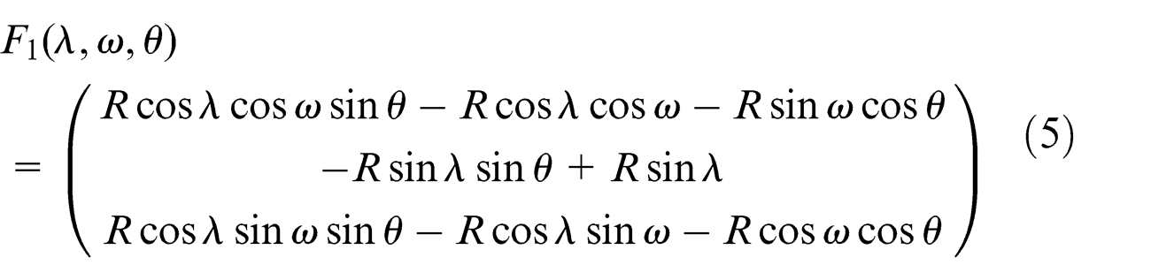
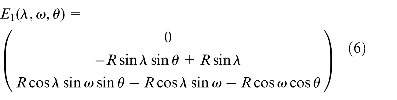
As shown in Figure 1, the CC point C1 is located as θ = π/2. Projecting F1(λ, ω, θ) to the YL–ZL plane, we will get the effective cutting shape E1(λ, ω, θ) of the flat-end cutter of the given CC point, which is an eclipse
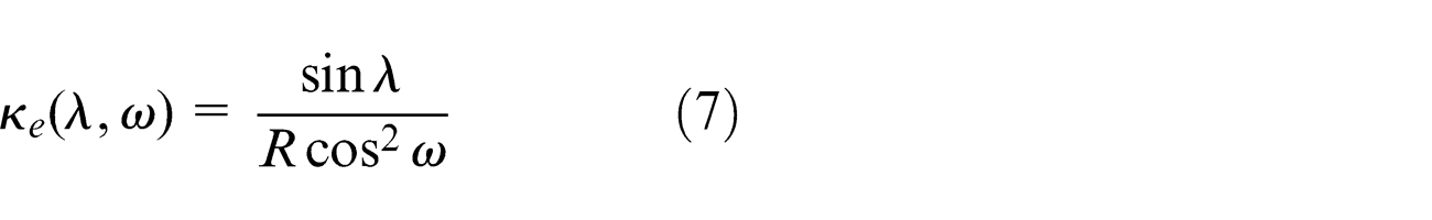
Also, the curvature of E1(λ, ω, θ) at the current CC point C1 (θ = π/2) can be calculated as follows
Designing the optimal tool orientation
The contact order between two surfaces at a point is an important concept in CNC machining. The higher the contact order between the designed surface and the cutter envelope surface, the more material will be cut off. In this section, the optimal tool orientation is designed to make the contact order of the designed surface and the cutter envelope surface maximal.
Second-order and third-order contact conditions
In this section, it is shown how to achieve the maximal contact order for machining a cyclide using five-axis CNC machines with a flat-end cutter.
Generally, the contact order of two surfaces S0 and S1 at a point
Theorem 3.1
Let S0 and S1 be the designed surface and the cutter envelope surface tangent at a point
Note that the cutter envelope surface is always convex. Then, the contact order can only be 1 if the machine surface is convex and higher contact order can be achieved only for concave surfaces.
If the tool moves along the iso-parametric curve
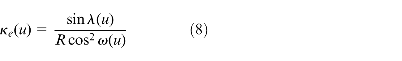
From Theorem 3.1 and equations (2) and (8), we have the following criterion for second-order contact of cyclide patches.
Lemma 3.2
Suppose
The third-order contact condition is given below.
Lemma 3.3
Suppose
where R is the radius of the bottom circle of the cutter.
The proof of Lemma 3.3 can be found in Appendix 1.
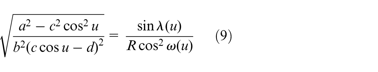
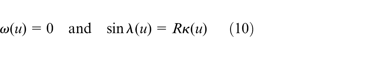
For a given parameter u*, by equations (3), (9), and (10), the optimal tilt angle and yaw angle can be obtained as the following theorem and the proof of this theorem is listed in Appendix 2.
Theorem 3.4
Let R be the radius of the end circle of the flat-end cutter, κ(u) from equation (2), and Λ
l
, Λ
u
, Ω
b
from equation (3). The optimal tool orientation at a point
If
The contact order at point
The contact order is 2 if and only if
In five-axis CNC machining with a flat-end cutter, the highest contact order of the designed surface and the cutter envelope surface is 3. Therefore, in the proposed strategy of designing the optimal tool orientation, the contact order mentioned above could achieve the highest possible contact level.
Optimal and continuous tool orientation determination
In this section, we show how to obtain optimal and continuous tilt and yaw angles along an iso-parametric curve. In five-axis CNC machining, the tilt and yaw angles between two adjacent CC points along a tool path cannot have jumps because of the machine ability. Therefore, the change rate of the tilt angle and yaw angle must be confined in a reasonable range.
Let the tool move along the iso-parametric curve p(u) =
Let
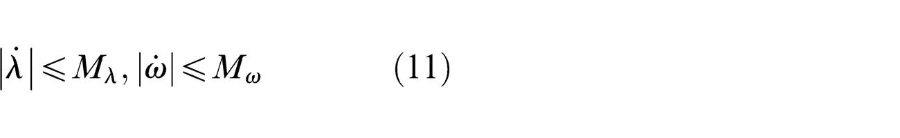
where Mλ and Mω are the given maximum change rates of λ and ω, respectively.
By equations (2) and (8), in order to be local gouging-free, κ(u) ≤ κe must be valid, that is,
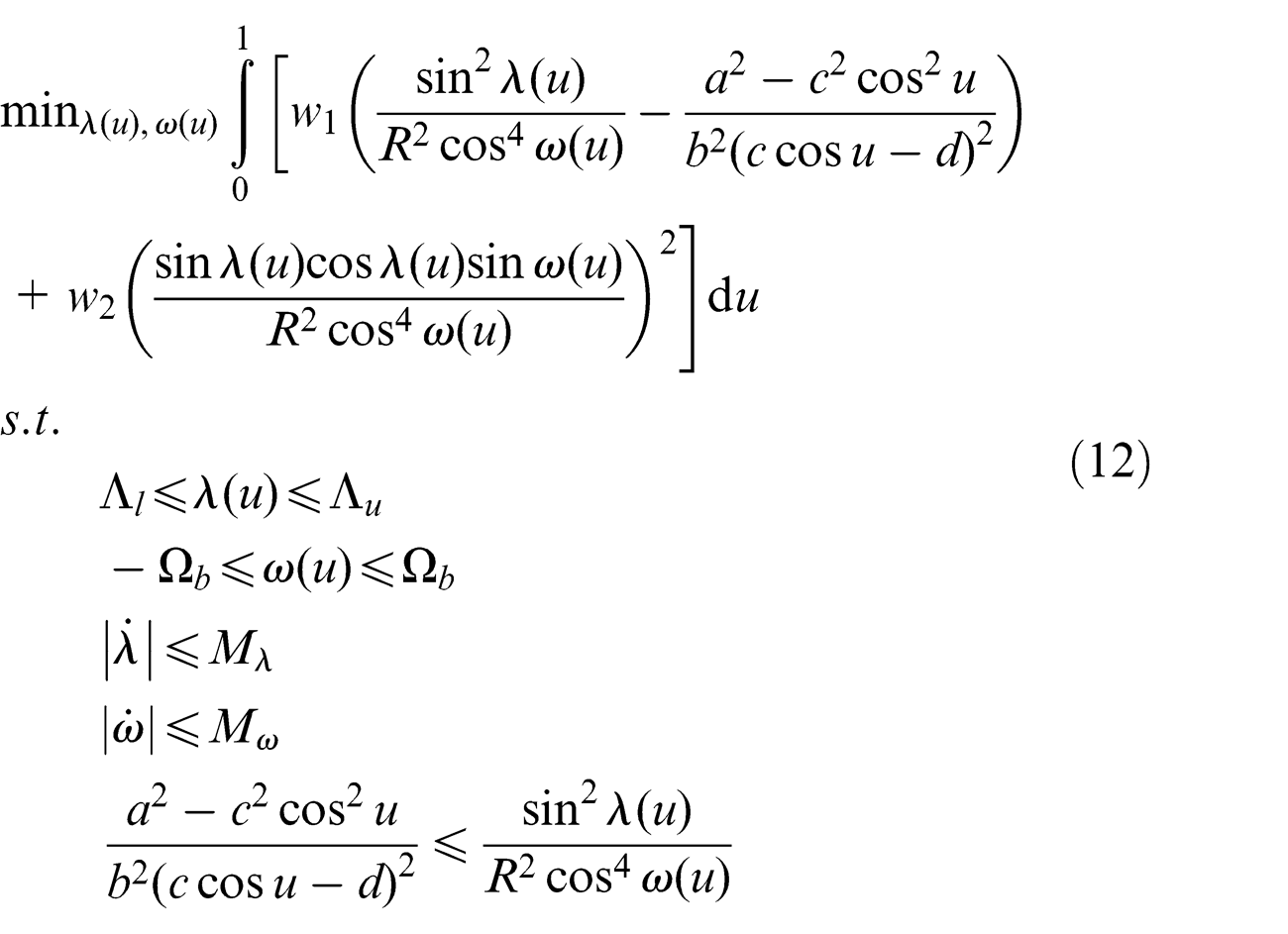
where w1 and w2 are the weights of the optimization problem, which are set to be w1 = 3000 and w2 = 1 in the examples given in section “Tool-path generation for a cyclide spline” to show the priority of the second-order contact condition. Due to equations (9) and (23), the objective function is to make the “total” contact order as large as possible under the given constraints.
The infinite state optimization problem (12) can be approximately solved by transferring the problem into a finite state optimization problem. The parameter interval [0, 1] of u is divided into N equal parts with the knots ui = iΔu, i = 0,..., N, where
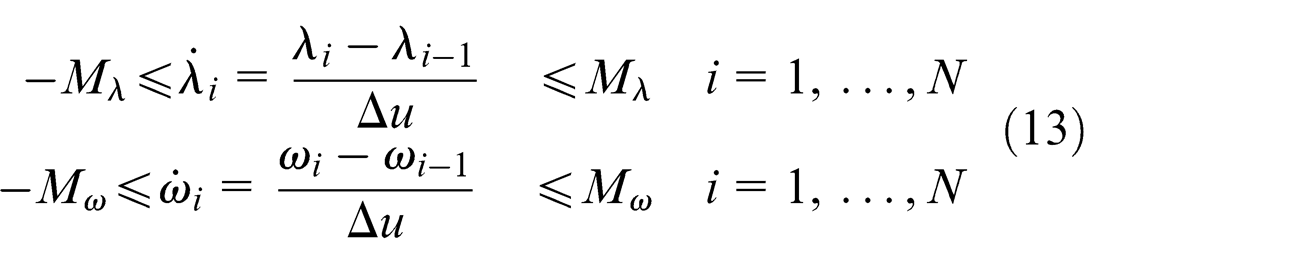
Using equation (13), problem (12) is discretized into the following finite state optimization problem
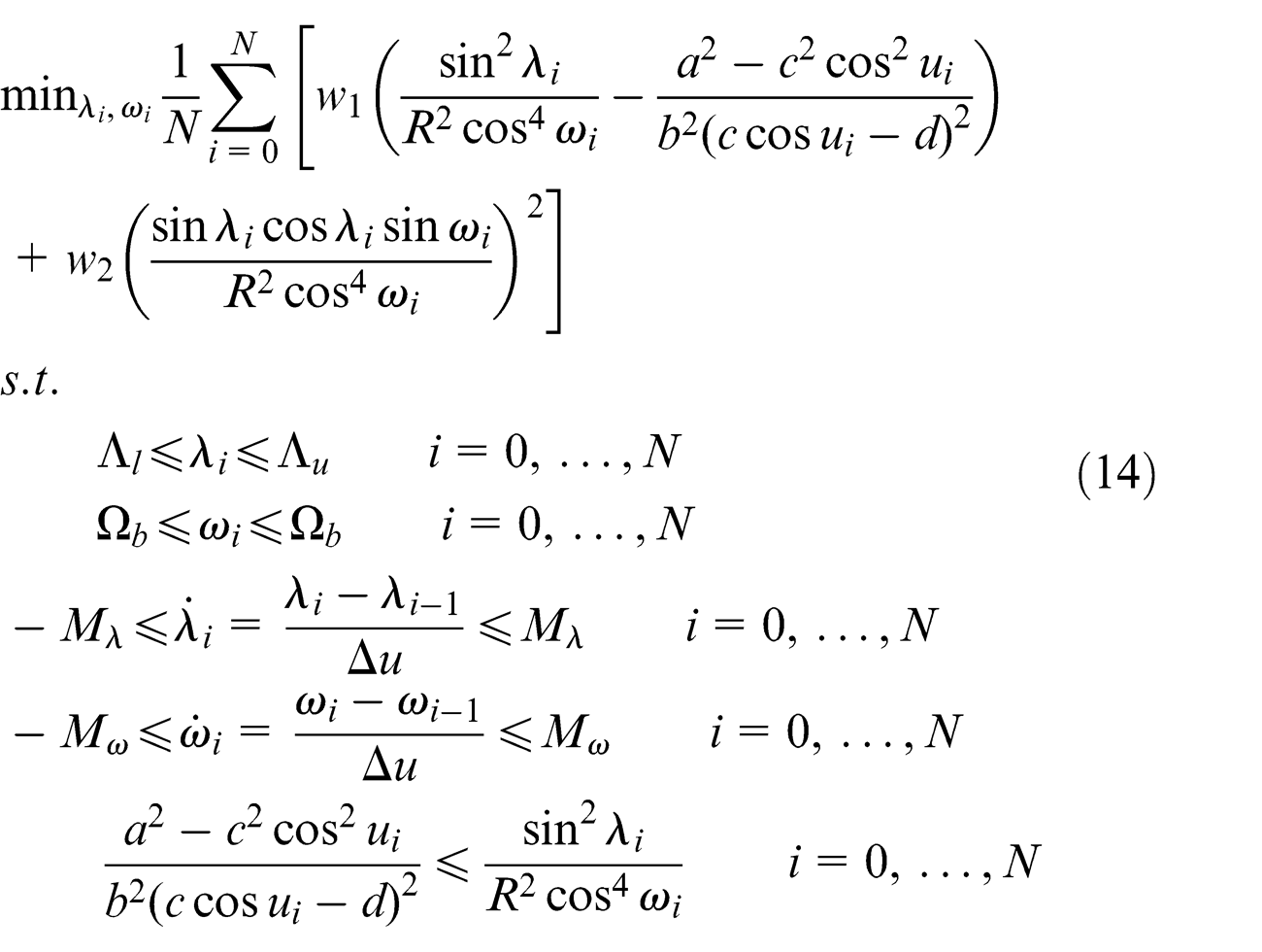
Problem (14) can be solved effectively with the Sequential Quadratic Programming (SQP) method, 26 as shown in section “Tool-path generation for a cyclide spline.”
Tool-path generation for a cyclide patch
In this section, two methods to generate the tool path are given. The first one is based on iso-parametric strategy, which is also iso-curvature in the situation of cyclide patches machining. The second one is based on the iso-scallop strategy, which is the most effective strategy. Let h > 0 be the tolerance bound for the scallop height. We will present algorithms to generate optimal tool paths without violating the scallop bound.
Suppose a cyclide patch
Calculating the step-over
In this section, it is shown how to compute the step-over, which is a key quantity to generate a new tool path. Roughly speaking, the step-over is the distance between corresponding points on two adjacent tool paths.
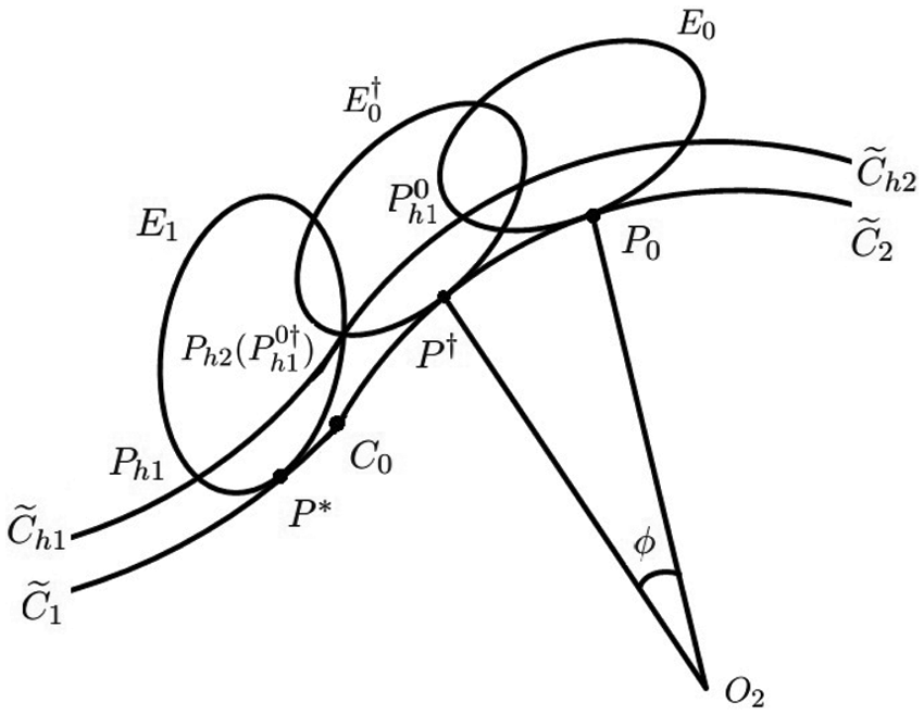
Suppose that a tool path p(u) =
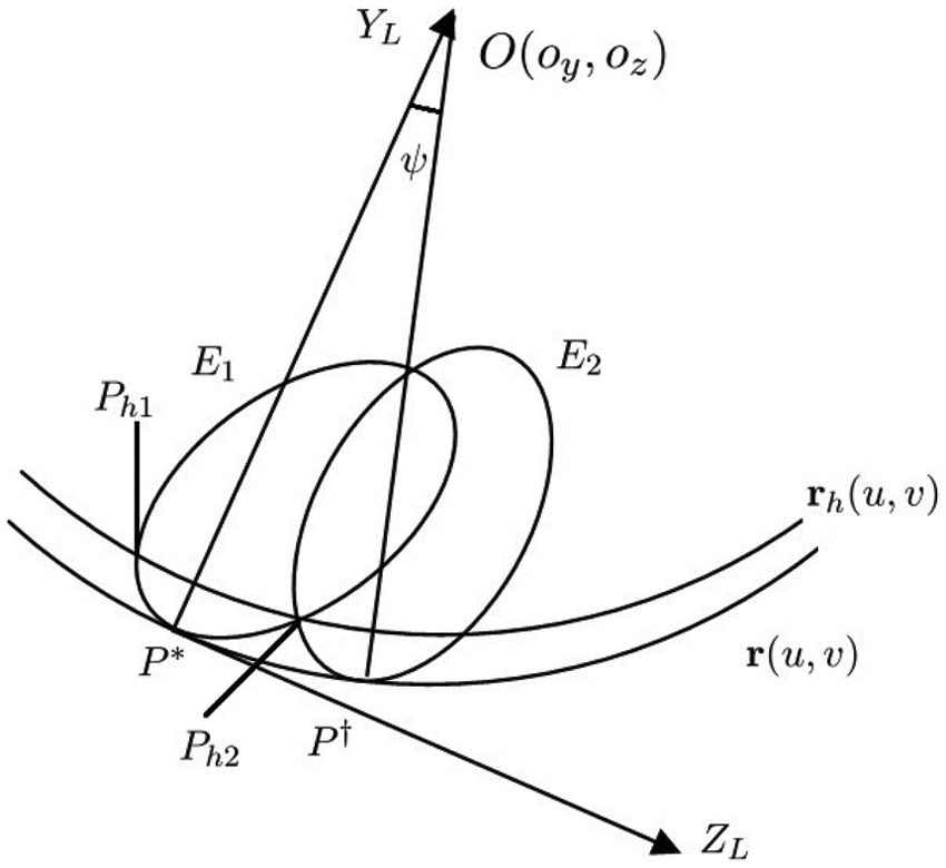
E1 and E2.
The first step to compute P† is to determine the tilt and yaw angles for point P†. By Theorem 3.4, the optimal tilt and yaw angles for a point depend only on the value of u. Therefore, we can assume that the tilt and yaw angles of P† are the same as that of P*, which are assumed to be λ* and ω*. As a consequence, the ellipses describing the effective cutting shapes are congruent at points P* and P† due to equation (5).
As shown in Figure 2, the effective cutting shapes of the CC point P* and its corresponding CC point P† are E1 and E2, respectively, which are the intersection of the cutter envelope surfaces with the plane H*. From the discussion given above, E2 is obtained from E1 by rotating an angle ψ around point O.
Let
Let Ph1 and Ph2 be the intersections of E1 and
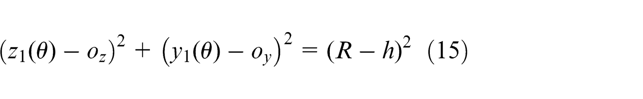
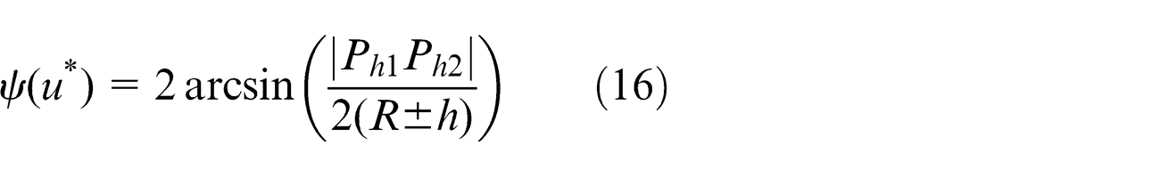
where z1(θ) = R cos λ* sin ω* sin θ − R cos λ* sin ω* − R cos ω* cos θ, y1(θ) = −R sin λ* sin θ+R sin λ* due to equation (6). Since h is very small comparing to R, equation (15) has two real solutions which represent Ph1 and Ph2. Furthermore, the angle ψ can be computed as
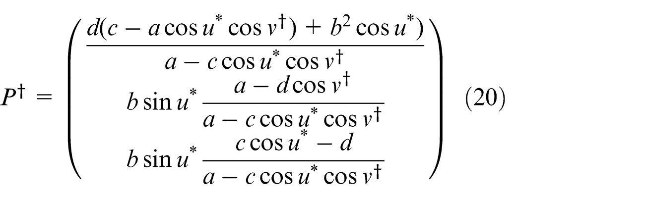
Since E2 is obtained from E1 by a rotation around O about an angle ψ, in the local coordinate system XLYLZL, P† can be obtained from P* as follows
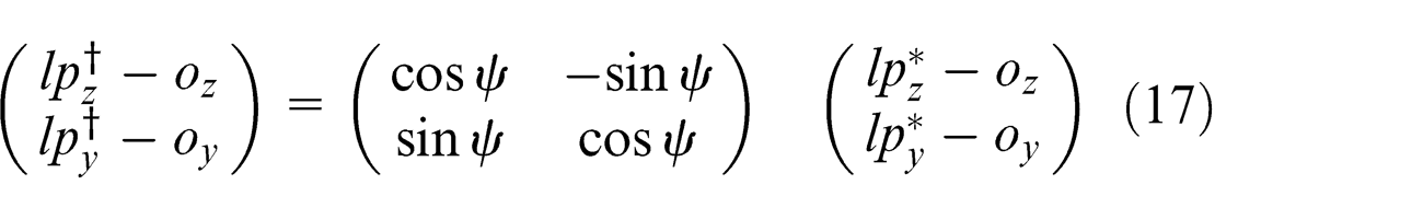
where
In MCS,
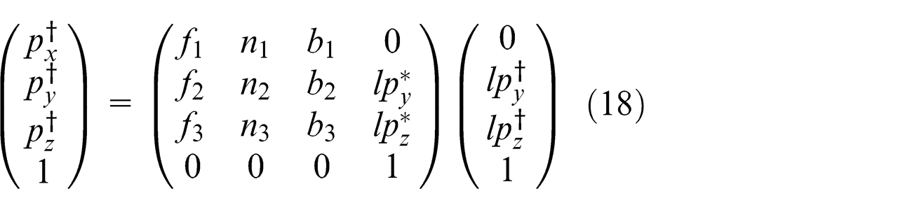
where
Furthermore, the step-over l(u*) can be obtained by the following equation
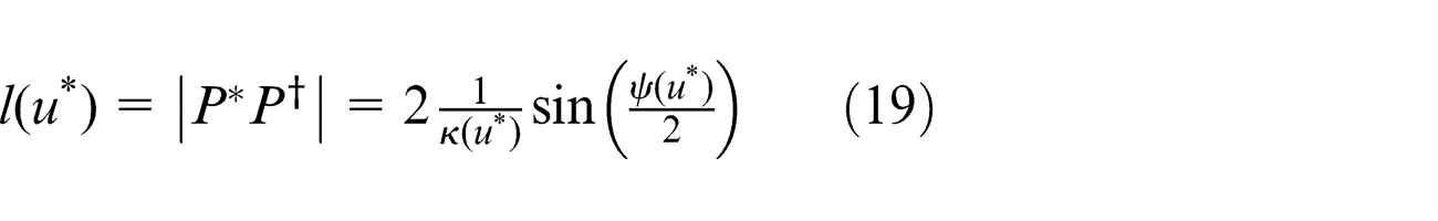
where
Remark 4.1
Notice that for one cyclide patch and one fixed u*, equation (15) needs only to be solved for one time. The points on other tool paths can be obtained by using equations (17) and (18) successively.
Iso-parametric tool-path generation
In this section, a method is given to generate iso-parametric tool path, which are desirable for cyclide splines since such curves are arc splines. So, an iso-parametric tool path for a cyclide is also iso-curvature meaning that the normal curvatures of the points on the tool path are the same.
Suppose that we already have an iso-parametric tool path
By properties C1 and C2 given in section “Preliminaries,” when the tool moves along the iso-parameter curves
where P† is from equation (18).
At the corresponding points P* and P†, the two tool paths are iso-scallop. But, at other corresponding points, the two tool paths are not necessarily iso-scallop. In order to preserve the scallop height bound h, we need to find the smallest v† such that equation (20) is valid. In other words,
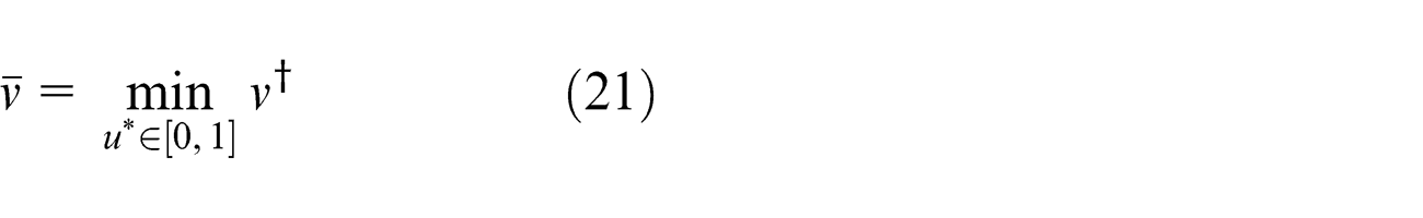
where v† satisfies constraint (20).
Problem (21) can be solved efficiently as follows. The parameter interval [0, 1] of u* is divided into N equal parts with the knots ui = iΔu, i = 0,..., N, where
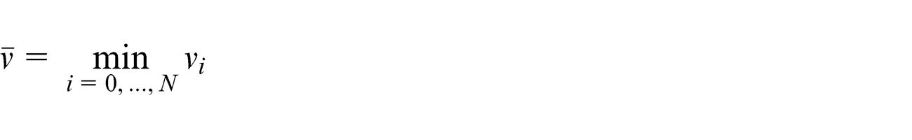
Then
Iso-scallop tool-path generation
In this subsection, a method is presented to generate iso-scallop tool path for a cyclide patch. For cyclide patches, the iso-scallop tool path is generally not iso-parameter and the intersection curve of the designed cyclide patch and the plane orthogonal to the feed direction is no longer an iso-parameter curve. That will increase the computational time and even make the problem computationally unsolvable. In order to use the properties of the cyclide, the following assumption is assumed: we always use the v iso-parameter curves to estimate the scallop height, meaning that the results given in section “Calculating the step-over” are still usable.
The initial tool path is given by two sets of data. First, it is represented by a set of rational functions (u(t), v(t)), t ∈ [0, 1], that is, the tool path is
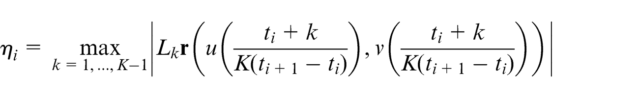
The first step is to generate a coarse tool path. For each Ci =
The second step is to refine the coarse tool path. For each i = 1,..., M − 1, check whether the chord error is violated between
where
If the chord error is violated between
The third step is to fit the points Dj as a curve on the cyclide. To do that, we fit the points
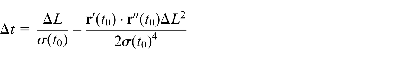
Finally, iso-chord error points are generated on the new tool path as follows. Let
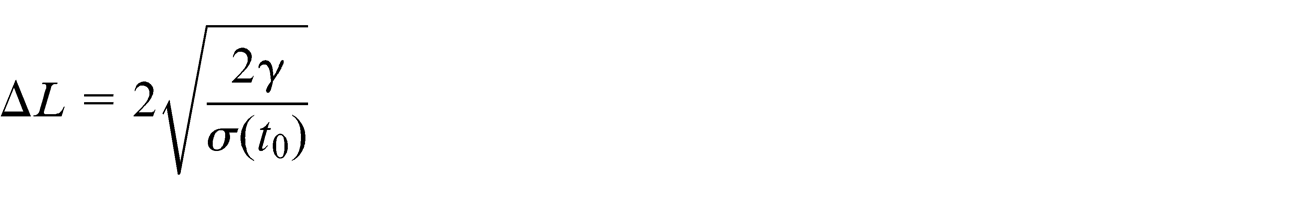
where
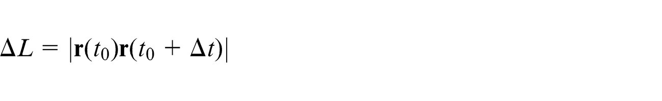
Because the distance ΔL is small and can be approximately treated as the arc length, the following formula can be used to compute Δt 29
Now, the new iso-scallop and iso-chord error tool paths are generated and represented by a set of CC points
Tool-path generation for a cyclide spline
In this section, it is shown how to generate the results in sections “Designing the optimal tool orientation” and “Tool-path generation for a cyclide patch” to a cyclide spline.
In practice, a piece of free-form surface is approximated by various cyclide spline surfaces.17–21 The simplest cyclide spline surface is described below. Let u0 = 0 < u1 < ... < un = 1 and v0 = 0 < v1 < ... < vm = 1 be numbers. A cyclide spline is of the following form
where
We will show how to update the methods proposed in this article to generate iso-parametric or iso-scallop tool path for cyclide spline surfaces. It is easy to see that the results given in section “Second-order and third-order contact conditions” concern of a point on one cyclide, so nothing need to be modified. In section “Optimal and continuous tool orientation determination,” problem (14) needs to be modified as follows: when ui changes from one piece of cyclide to another one, the parameters a, b, c, and d need to be changed to the parameters of the corresponding cyclide. The results in section “Calculating the step-over” need to be modified when E1 and E2 are on two different cyclide patches, and when this is done the results in section “Iso-parametric tool-path generation” can be easily extended to cyclide splines and the results in section “Iso-scallop tool-path generation” need minor modification. Therefore, in the rest of this section, results in sections “Calculating the step-over” and “Iso-scallop tool-path generation” are considered for a cyclide spline.
Using notations introduced in section “Calculating the step-over.”Figure 3 shows the plane H* containing the v parametric line
Tool-path generation on the patch boundary.
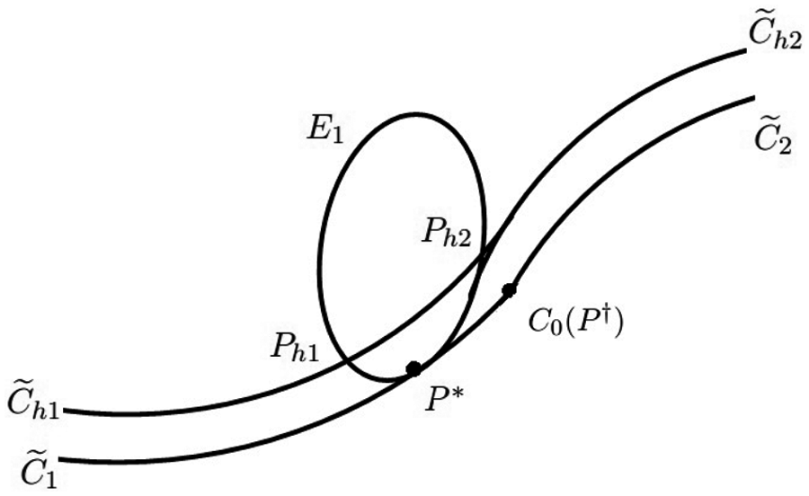
We now show how to compute P†. Using equation (15) and
If Ph2 is on
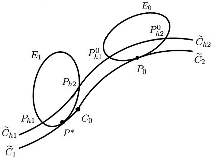
Fix a point P0.
Rotate P0 to P†.
We now consider the procedure given in section “Iso-scallop tool-path generation” to generate iso-scallop tool path. The optimal tilt and yaw angles obtained by solving problem (14) is along the u parametric curves. As a result, when the iso-scallop tool path crosses the boundary of two cyclide patches, the tilt and yaw angles are generally not continuous. To deal with this problem, we add a new step, to be described in the next paragraph, between step 2 and step 3 of the procedure given in section “Iso-scallop tool-path generation.”
Let the refined tool path be represented by the CC points
Example
First, an example of generating tool paths for a single cyclide patch is given.
Example 1
The cyclide patch is given in equation (22) and is shown in Figure 6, where the red curve is the initial tool path
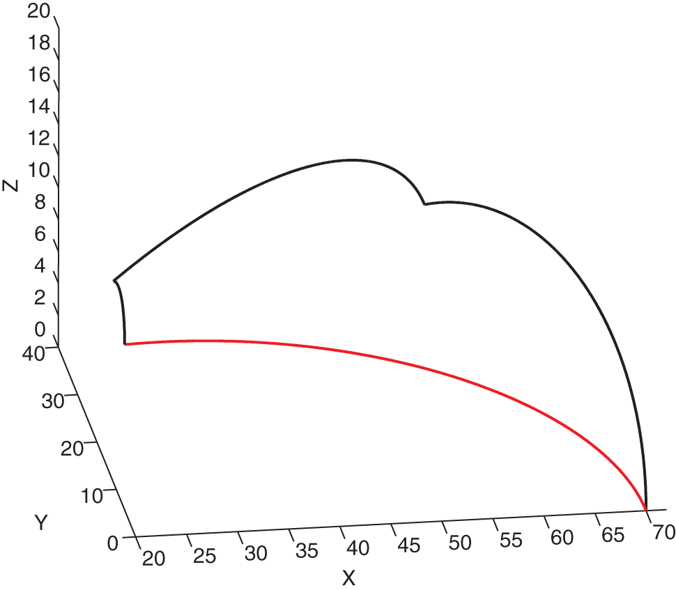
Designed cyclide patch.
The radius of the tool is 4 mm. The constraints for the tilt angle and the yaw angle are as follows: λ ∈ [5°, 45°], ω ∈ [0°, 60°],
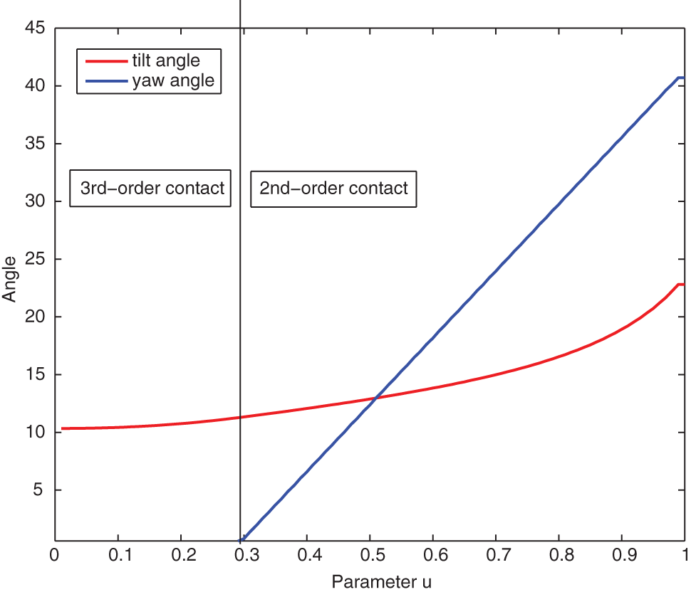
Optimal tilt and yaw angles.
The iso-parametric tool paths and iso-scallop tool paths are obtained with methods in sections “Iso-parametric tool-path generation” and “Iso-scallop tool-path generation” and are shown in Figures 8 and 9, respectively. The total length of the iso-parametric tool paths is 560 mm, while the total length of the iso-scallop tool paths is only 324 mm, about 57.86% of that of the iso-parametric tool path. It is obvious that by using the iso-scallop strategy, the machining efficiency can be enhanced.
Iso-parametric tool paths.
Iso-scallop tool paths.
Example 2
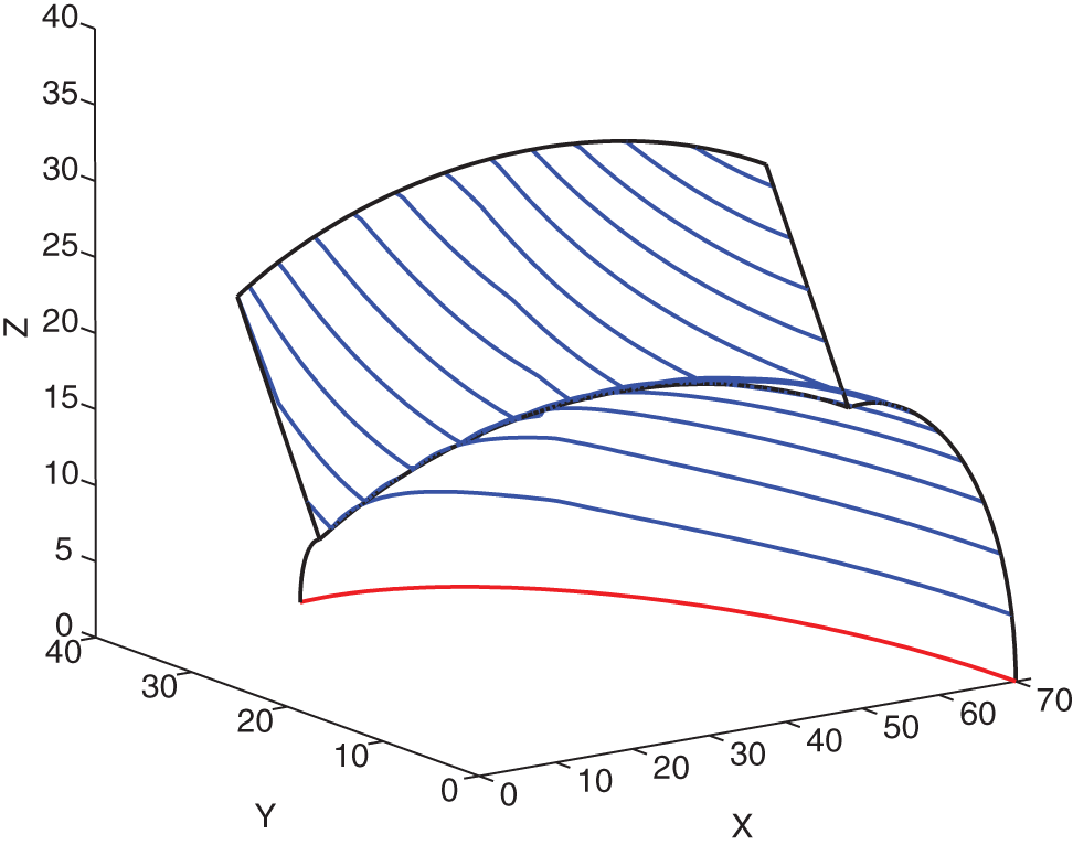
In this example, the tool paths of two cyclide patches are given in order to test our algorithm for generating tool paths on the boundary of the patches. The first patch is from Example 1 and the second one is part of a cylinder whose radius is the same as that of the boundaries of the first patch as shown in Figure 10.
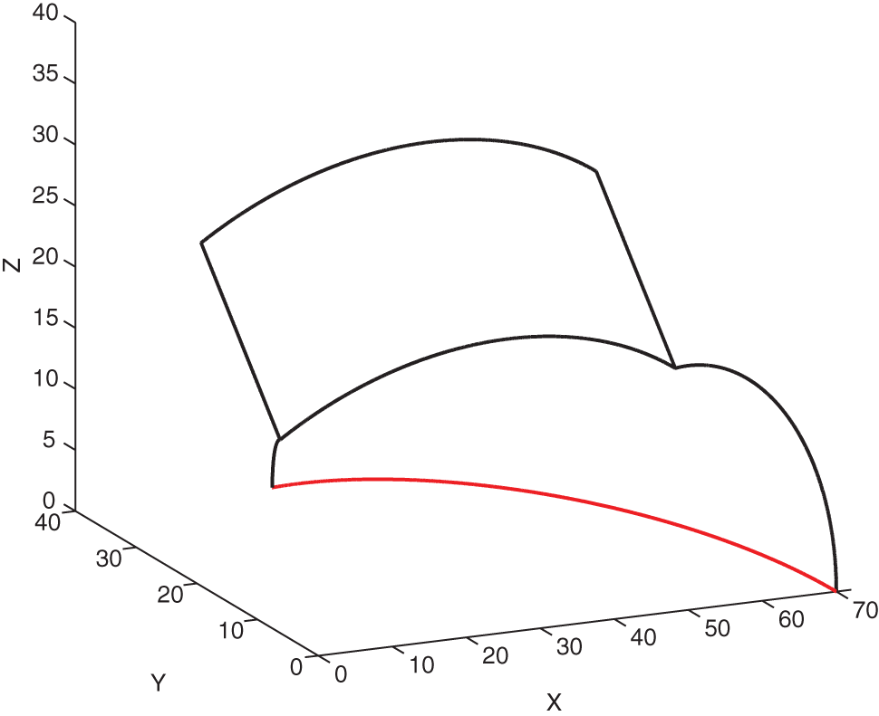
Designed two cyclide patches.
The machining parameters of this example are the same as those of Example 1 and the optimal tool orientations of the first patch are also the same as Example 1. The optimal tool orientations of the second patch can be calculated using the method in section “Designing the optimal tool orientation,” which are quite simple: the optimal tilt angle λ≡ 5° and the optimal yaw angle ω≡ 0°.
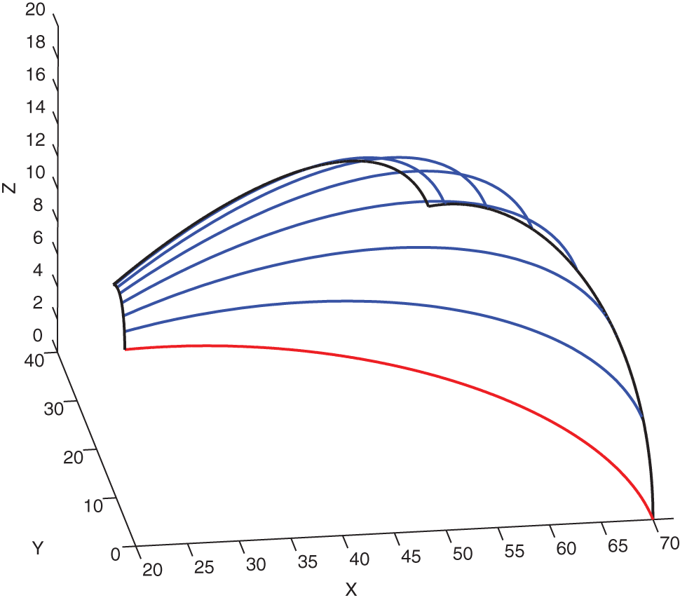
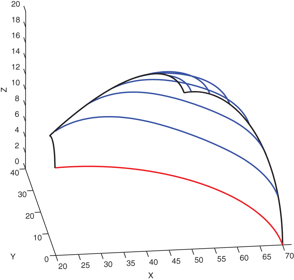
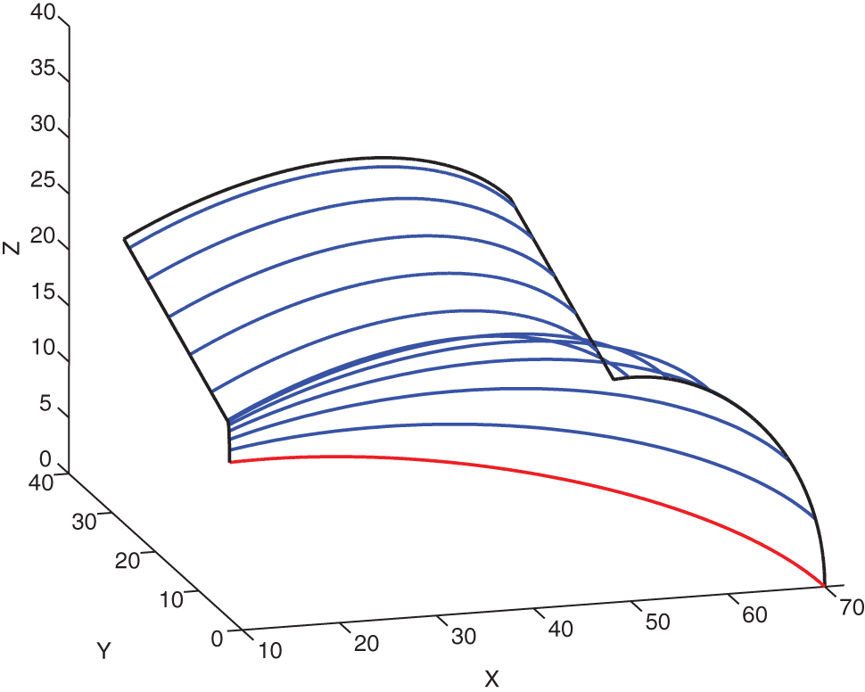
After the optimal tool orientations are determined, the iso-parametric tool paths are generated by the method in section “Iso-parametric tool-path generation” and are shown in Figure 11. The iso-scallop tool paths are generated with methods in section “Iso-scallop tool-path generation” and section “Tool-path generation for a cyclide spline” and are shown in Figure 12
Iso-curvature tool paths.
Iso-scallop tool paths.
In what follows below, we will explain how the iso-scallop tool paths are generated. Following the first three steps of the method given in section “Iso-scallop tool-path generation,” the second tool path is generated and is shown as the green one in Figure 13. However, since the optimal tilt and yaw angles for the two patches are computed separately, the tool orientation has discontinuous points on the boundary, as shown in Figure 14.
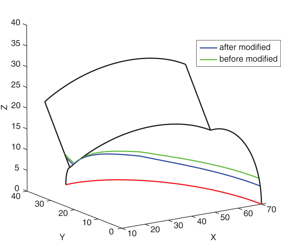
Second tool path before and after smoothing the tilt and yaw angles.
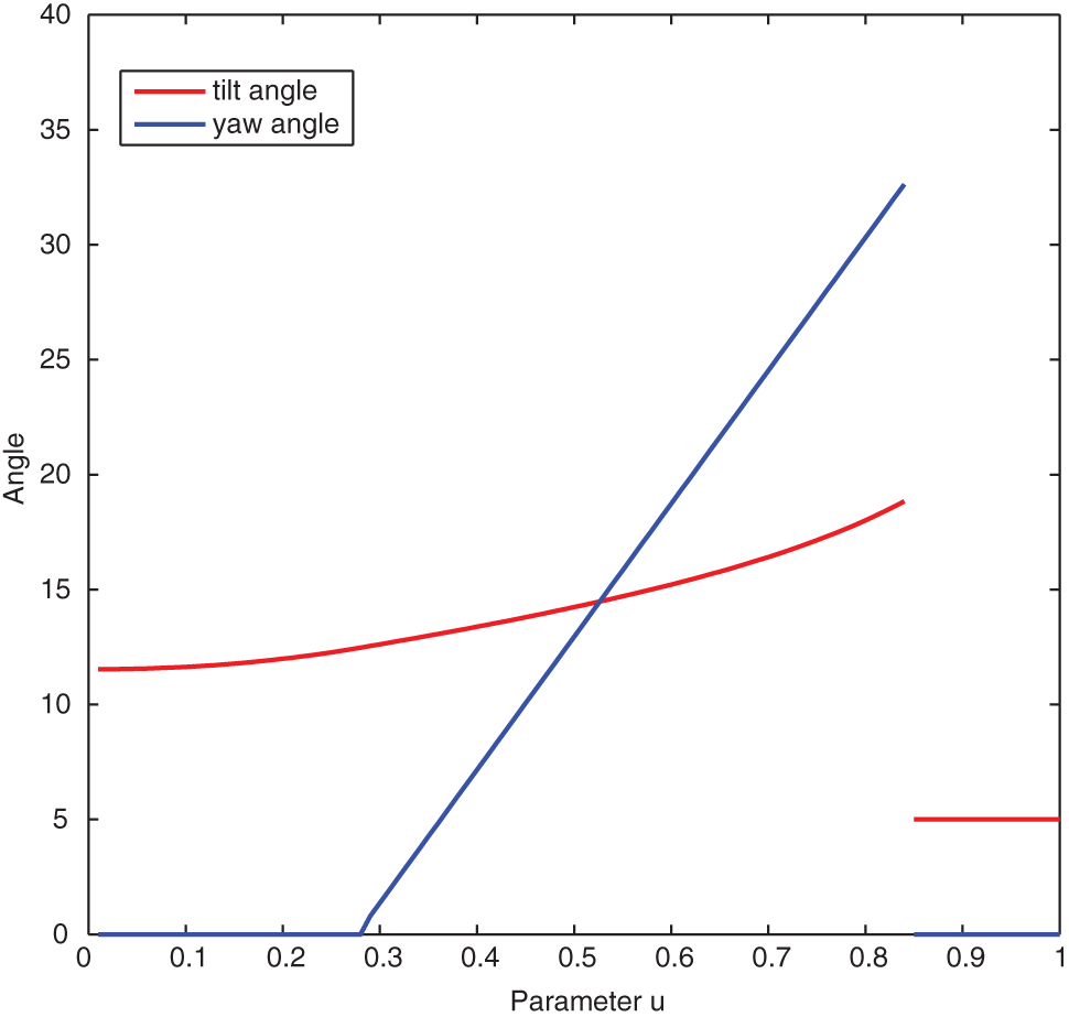
Tilt and yaw angles for the second tool path before smoothing.
Now, following the methods proposed in section “Tool-path generation for a cyclide spline,” a modified version of optimization problem (14) is solved to obtain the optimal smooth tool orientations which are shown in Figure 15. With these new tool orientations, a new tool path is generated and is shown as the blue one in Figure 13. As expected, the bandwidth of this new tool path is smaller than the old one. Repeating the procedure, the iso-scallop tool paths with smooth tool orientations can be obtained and are shown in Figure 12.
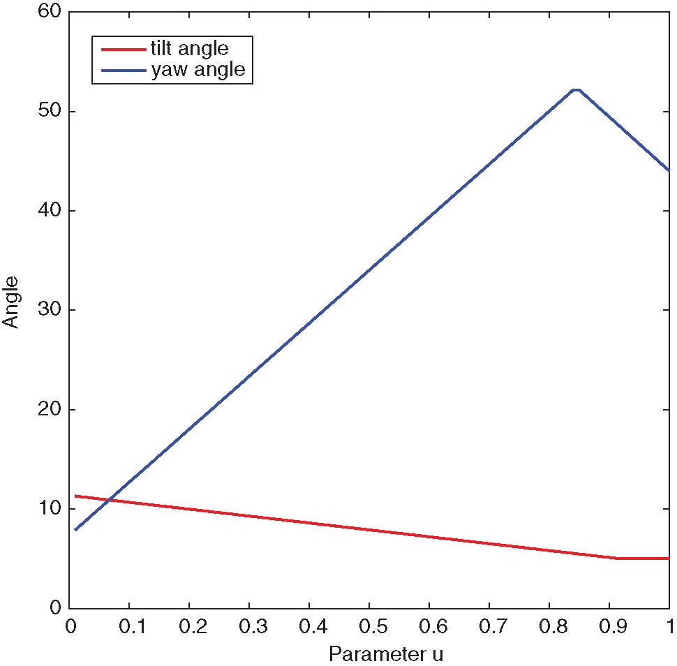
Tilt and yaw angles for the second tool path after smoothing.
Conclusion
A new five-axis CNC machining tool-path generation method for cyclide patches is presented in this article. Conditions for second- and third-order contact between a cyclide and the cuter envelope surface for a flat-end cutter are given. The optimal tool orientations along a whole path on cyclide patches are computed by solving only one optimization problem, which guarantees the contact order of the designed surface and the cutter envelope surface as high as possible under the constraints of a given maximum tool orientation change rate. Based on the optimal tool orientation and properties of the cyclide patches, efficient methods are proposed to generate iso-parametric and iso-scallop tool path. There is no need for the proposed model to approximate the designing surface or the effective cutting shape of the cutter as circle locally, or to solve a complex system of equations. Combining existing methods on fitting arbitrary surfaces with cyclide spline surfaces, a general method for tool-path generation is proposed.
Footnotes
Appendix 1
Appendix 2
Acknowledgements
The authors want to thank Professor Wenping Wang for bringing cyclide surfaces to our attention.
Declaration of conflicting interests
The authors declare that there is no conflict of interest.
Funding
This work was partially supported by a grant from NSFC (60821002).