
Abstract
Currently, to satisfy the stringent requirements on the physical properties of sculptured surfaces, workpiece machining attempts to guarantee the level of machining accuracy while improving the efficiency as much as possible. Because of the characteristics of the sculptured surfaces, the machine tool is usually run at a lower feedrate to avoid large impact forces. However, this sacrifices machining time and still may not meet the requirements. This article presents a novel minimum-time feedrate schedule method to improve the machining efficiency for five-axis machining considering the surface characteristic constraints. First, the mapping relationship between the surface characteristic and the kinematical parameters is constructed by analyzing the following error on each axis. After that, the new constraint conditions on machine tool kinematics limitation and its continuity constraints are given to address changes in the curvature. Next, a new acceleration/deceleration feedrate schedule method is presented based on quintic feedrate smooth profile to minimize the impact force as much as possible. Thus, a novel minimum-time feedrate schedule based on the bidirectional feedrate schedule algorithm is proposed to improve machining efficiency while respecting various constraints. Finally, a sculptured surface with varied curvature is used to illustrate the significant reduction in processing time and improvement in surface quality in large curvature region after scheduling. The simulation and experimental results show that the proposed method can improve the machining efficiency while guaranteeing the machining accuracy.
Introduction
Five-axis machine tools are widely used to process many important industrial parts, such as die, impeller, blade, and crankshaft. These parts typically have complex surface features and are quite valuable. Such complicated geometrical features could easily result in a high impact force and poor kinematic effect on the machine tool. To guarantee the machining accuracy, the machine tool is typically set to a relatively low feedrate during manufacturing. As a result, the machining will take a long time to implement. Therefore, both industrial efforts and research studies are highly focused on improving the machining efficiency on these unique sculptured surfaces without loss of accuracy of parts.
The initial research was on the feedrate schedule of the machine tool; such schedule appeared to have a direct effect on the machining efficiency. The primary goal of feedrate schedule was to establish a minimum-time strategy based on the running conditions of the Computer Numerical Control (CNC) machine tools. 1 According to the types of constraints, the feedrate planning process could be divided into two types: the force constraint and the kinematic constraint. Guzel and Lazoglu 2 introduced an enhanced model to predict the cutting forces based on surface topography. A lower feedrate is used in the position of large cutting force, whereas a higher feedrate is used in the position where the cutting force is small. In this manner, the processing time is shortened and the machining efficiency is improved. Wang 3 developed a solid modeling approach involving calculation of the volume of metal removal, the chip load, and average force. The approach can be used to estimate and improve higher productivity. Liang et al. 4 proposed an original approach to schedule the feedrate and then reduce the cutting time using material removal rate (MRR). Erdim et al. 5 proposed both MRR and force-based feedrate scheduling strategies to improve machining efficiency. Qian et al. 6 introduced an off-line rescheduling feedrate to reduce machining time while controlling chip thickness, metal removal rate, and resultant forces. Fan et al. 7 presented a time-optimal feedrate planning method with complex constraints, including the motor torque constraint and the friction error constraint. Within the maximum allowable cutting force, Zhang et al. 8 proposed the integration of force prediction and feedrate scheduling of geometric and mechanistic milling models in five-axis CNC free-form surface machining. And this could decrease the machining time significantly along the toolpath. These methods effectively optimize the feedrate of machine tool to improve machining efficiency. However, in these methods, some kinematic parameter constraints are ignored, including acceleration and jerk. If acceleration and jerk exceed their limits, it will generate a huge dynamic load and cause vibration for machine tools. Thus, the machining quality will be reduced, and the dynamic stiffness and service life of machine table will be affected. Therefore, it is very significant to consider the kinematic parameter constraints.
The further feedrate schedule research for improving productivity along entire five-axis toolpath is constrained by kinematic constraints. Sun et al. 9 proposed an adaptive feedrate scheduling method with velocity and acceleration constraints for precision five-axis machining to reduce machining time. Lu and Chen 10 presented a genetic algorithm based on S-curve acceleration/deceleration scheme to increase processing efficiency. Sencer et al. 11 introduced a feed scheduling algorithm for CNC systems to minimize the machining time for five-axis contour machining of sculptured surface. The time-optimal feed motion is obtained by iteratively modulating the feed control points of the B-spline. And this is conducive to maximize the feed along the toolpath without violating the programmed feed and the drives’ physical limits. Bharathi and Dong 12 proposed a feedrate optimization method under velocity and acceleration constraints. Beudaert et al. 13 proposed a unified and efficient solution to minimize the machining time by making best use of the kinematical characteristics of the machine, including velocity, acceleration, and jerk limits. This minimum-time feedrate profile was computed by intersecting all the constraints due to the drives in an iterative algorithm. Fan et al. 14 presented the time-optimal velocity planning problem for five-axis CNC machining along a given parametric toolpath under acceleration and jerk constraints. A polynomial time algorithm with computational complexity O (N3.5) was given to find the optimal solution to schedule feedrate and improve machining efficiency. Du et al. 15 proposed a locally optimal transition method under acceleration and jerk constraints, which used a two-step strategy to generate a blended toolpath composed of cubic Bezier curves and line segments, and the simulation and experiment results demonstrated that machining time can be significantly reduced. Although, all these methods consider the kinematic constraints, including feedrate, acceleration, and jerk, the continuity of jerk is ignored which may cause dramatically vibration and impact to reduce machining quality. Meanwhile, the maximum feedrate and acceleration remain constant over the entire machining process, which ignore the effect of sculpture surface features on the maximum velocity and acceleration on any axis. Therefore, it is necessary to consider the continuity of kinematic parameter constraints and the sculpture surface features.
Many articles have shown that the surface features have an influence on the kinematics of machine tool. Bi et al. 16 developed a novel analytical five-axis path-smoothing algorithm for the high-speed machining of a linear five-axis toolpath, which emphasized the importance of curvature for feedrate schedule. Fan et al. 17 found the curvature of surface has an influence on acceleration and jerk, but the primary effect is on feedrate. Ji et al. 18 provided a mathematical surface model composed of several sub-segments related to the curvature. The optimization method was established according to the surface characteristic. The results indicated that the path of acceleration and jerk not only was smooth but also achieved the high accuracy of workpiece. Ye et al. 19 proposed an interpolation method based on the look-ahead algorithm according to the curvature of the trajectory. Jia et al. 20 studied the interaction characteristic between the varied curvature features and feedrate trajectory error. Accordingly, in the optimization model, the constraint on feedrate or acceleration should be a flexible value based on the geometrical features of surface. In other words, the changeable characteristics of the surfaces must be taken into account during the feedrate scheduling. Therefore, studies between the surface characteristics and kinematic constraints still must be performed.
Moreover, a smooth toolpath is also conducive to improving the machining efficiency. Each five-axis toolpath included cutter tip and orientation data. 21 Compared with discrete data format, the five-axis toolpath, which is defined in terms of non-uniform rational B-spline (NURBS), has improved machining efficiency. And this is based on the advantages of improved path smoothness and reduced size of machining codes. Some researchers used the dual NURBS curve to construct a five-axis toolpath.22–25 On this basis, many users of NURBS demand high precision in three-dimensional (3D) contouring applications. To address this issue, Wang et al. 26 proposed a new sculptured surface test part with rich geometrical features called the S part. According to their analysis, the S part has a variety of curvatures, different curve continuous orders, and varying tool orientations. It can be considered a good example to demonstrate the optimization effect of a sculptured surface.
In this article, a new optimization method for machining efficiency is proposed considering the multiple constraints on the features of sculptured surface, kinematic parameters, chord error, and velocity continuity. In the “Feedrate schedule problem based on the surface characteristic” section, kinematic and geometric constraints are constructed based on the surface characteristic. “A novel minimum-time feedrate schedule algorithm” section presents the novel ACC/DEC schedule algorithm and the minimum-time feedrate schedule algorithm. In the “Simulation and experimental results” section, simulations and experiments are presented to evaluate the performance of the proposed method. Finally, the conclusions are given in the “Conclusion” section.
Feedrate schedule problem based on the surface characteristic
Generally, the feedrate schedule mainly aims at minimizing the machining time under the given constraints while considering the surface characteristic. These constraints, including the maximum velocity, acceleration and jerk of the five-drive axes, the maximum chord error, and the kinematic continuity, should be satisfied for the purpose of ensuring the machining accuracy, the kinematic performance of the machine tool, and the stability of the cutting process for machining sculpture surface.
Curve and surface curvature
Curvature is one of the main indices to evaluate the geometric characteristics of a curve since it reflects the camber of the curve. For a given arbitrary parameterized curve,
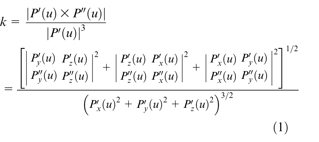
where
Maximum feedrate and acceleration constraint
To avoid excess impact on machining, the feedrate, acceleration, and jerk have limits on their maximum values. The traditional settings of these values are given as uniform values on each axis. Except for the maximum velocity limit Vmax, the conventional limits of acceleration and jerk are set as
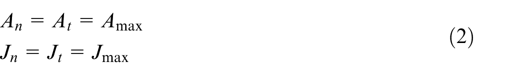
where Amax and Jmax are denoted as the acceleration and jerk limits on each axis for the CNC machine, respectively. An, At, Jn, and Jt are the centripetal acceleration, tangent acceleration, centripetal jerk, and tangent jerk, respectively. This demonstrates that if the feedrate profile is planned with the constraints of maximum centripetal and tangent acceleration, then the acceleration on each axis would not exceed the limitation and the same token for jerk. Therefore, tool chattering or system vibration due to high jerk can be avoided when adopting the settings.
To satisfy the machining accuracy, the traditional feedrate will always be set with a lower feedrate. Although the traditional settings meet the impact requirements, the uniform settings for the entire surface ignore the changes of the surface characteristics. The surface characteristics may greatly affect the machining efficiency and accuracy, especially for a surface with large curvature. This suggests that the feedrate on any axis is closely related to the surface characteristics.
Due to the high dimensionality of analysis of following error on five-axis, for brevity, a three-axis machine tool is adopted as an example and five-axis machine tool is similar to it. The trajectory error can be regarded as a comprehensive following error that results from the X-axis, Y-axis, and Z-axis linkages. Figure 1 shows the analysis for the following error along the X-axis, Y-axis, and Z-axis.
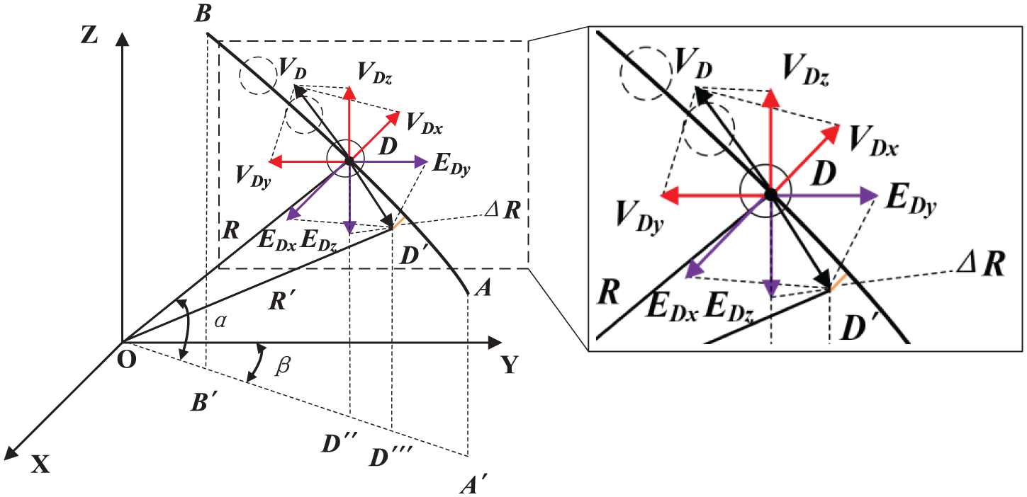
Analysis of the following error along any axis.
In Figure 1, the trajectory of tip point AB is an arc whose radius of curvature is R. When the machine tool is machining one surface, the ideal point position of the tip point is D, where the corresponding radius is
Therefore, the difference ΔR between the radius R′ of the actual tip point and the radius R of the ideal tip point is treated as the machining error caused by the dynamic following performance in the feed system.
From Figure 1, the following equations are obtained
According to the calculation formula of the following error on transitional axes, 27 the following errors in the X-axis, Y-axis, and Z-axis are obtained. Let the position gain of the X-axis, Y-axis, and Z-axis be Kppx, Kppy, and Kppz, respectively
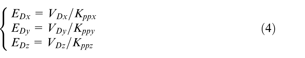
From Figure 1, the relationship between EDx, EDy, EDz, and DD′ 2 can also be obtained

As R is considerably larger than DD′. the triangle ODD′ can be regarded as a right triangle. Thus, the follow equation can be established
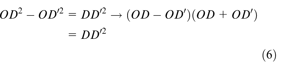
Next, substituting equation (5) into equation (6)
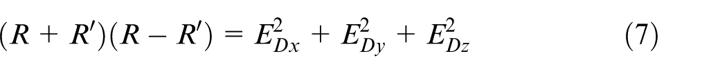
As R is approximately equal to R′, equation (6) can be written as
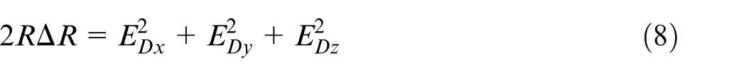
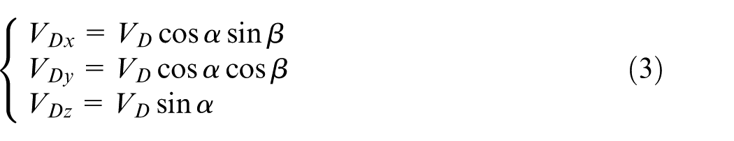
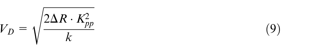
Assuming that all servo parameters are matched and R is equal to 1/k, which indicates that Kppx, Kppy, Kppz, and Kpp are equal to each other. The VD is obtained by the following equation
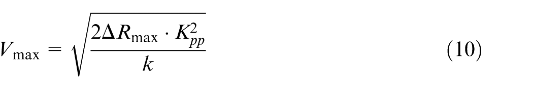
As the maximum difference ΔRmax and position gain Kpp are constant in the whole process of machining, the maximum velocity Vmax of transition axes can be further written as
From equation (10), for each transition axis, therefore, the axial velocity limits of transition axes VTmax are obtained by
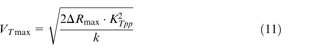
where ΔRmax and KTpp are the contour error limit and position gain of each transition axis, respectively.
Combined with the calculation formula of the following error on rotary axes, 28 the characteristics of rotary axes are similar to transition axes. Therefore, the mapping relationship between axial velocity limits on rotary axes VRmax and curvature is given as
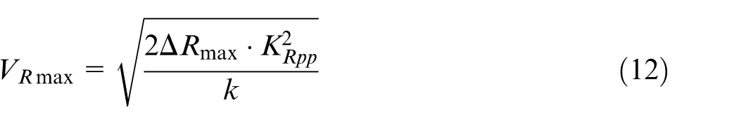
where the KRpp is the position gain of each rotary axis.
Integrated with equations (11) and (12), the mapping relationship between the maximum velocity Vmax of each axis for five-axis machine tool and curvature can be expressed as
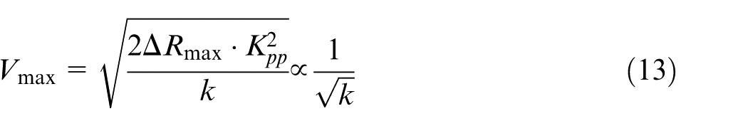
Equation (13) depicts the mapping relationship of each axis between the maximum velocity and curvature. It also can be seen that machining along a straight line with smaller curvature endures less impact than that along a curve with larger curvature. Therefore, the machine tool could be allowed to pass through a line with higher feedrate. Following this principle, a sculptured surface can be split into different segments with different maximum allowable values according to different curvatures. For the straight line reference curvature k0, when the curve curvature ki of surface segment ui is smaller than the k0, this curve can be regarded as a straight line. According to the curvature distribution of workpiece, for each axis, the maximum velocity V(ui)max in different segments is constrained by the following equations
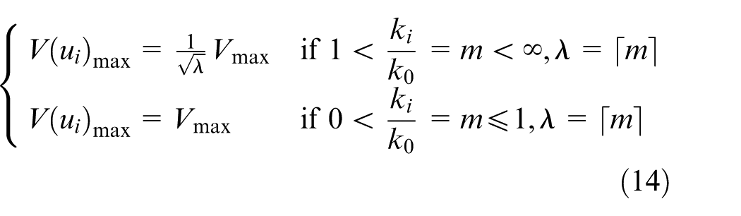
where the parameter m is a changing ratio because the curvature along the five-axis toolpath changes continuously. If m is relatively small, then a higher feedrate can be executed, and the machining productivity is expected to improve. Otherwise, the maximum feedrate must be reduced to keep the machine tool stable with the curvature changing. The λ denotes the minimum integer greater than m, and V(ui)max represents the maximum feedrate in the surface segment ui.
After the derivative of V(ui)max, the relationship between the maximum acceleration and the curvature in surface segment ui can be given as
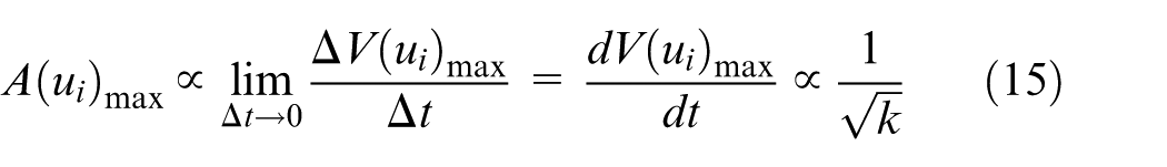
where A(ui)max represents the maximum acceleration in surface segment ui.
Similar to the feedrate, machining along a line could be allowed to pass through with a higher acceleration, which can reduce the processing time. In addition, the maximum accelerations in different segments are limited by
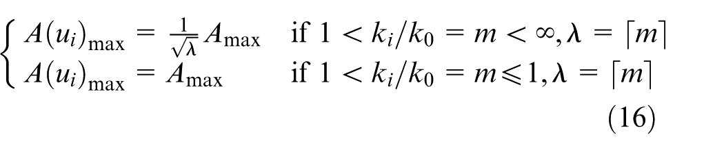
where the definitions of m and λ are similar to those in equation (14).
From equations (14) and (16), for the different segments, the machine tool is able to operate with different maximum feedrate and acceleration, which can fully exert machine tool capability to improve machining productivity while guaranteeing processing quality.
Feedrate constraints based on surface property
Although the maximum feedrate and acceleration have been limited according to surface characteristics in the “Curve and surface curvature” section, the feedrate with large curvatures in a five-axis toolpath still may violate the kinematic property for high-speed machining. To achieve an adaptive feedrate schedule for surface properties, three constraints, that is, chord error, centripetal acceleration, and jerk, are considered simultaneously.
Centripetal acceleration and jerk constraints
As shown in Figure 2, segment surface ui can be considered to be a part of circle. The feedrate is continuously changeable. This means that the ending feedrate in segment surface ui−1 is equal to the starting feedrate in segment surface ui. Here, the acceleration is primarily the centrifugal acceleration.
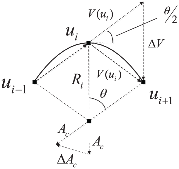
Feedrate determined by the allowable centrifugal acceleration and centrifugal jerk.
As seen in Figure 2, the acceleration Ac in segment surface ui can be expressed as
If the motion meets the acceleration limit A(ui)max, the feedrate V(ui) should be satisfied
Similarly, in Figure 2, the variation of the acceleration ΔAc between the two surface segments ui and ui+1 is also due to the change of the jerk. The jerk Jc is given by
where Ts denotes the time to move from segment surface ui to ui+1. As pictured in Figure 2, the relationship between ΔAc and Ac is
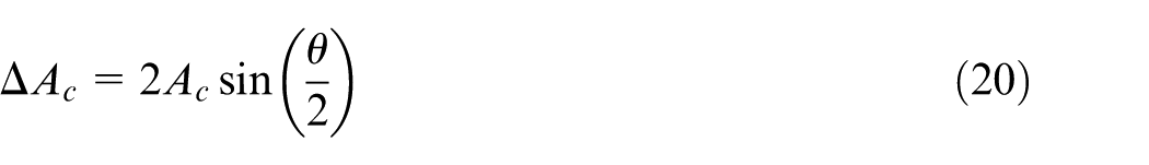
The center angle θ satisfies
Because the angle θ is very small, it is can be expressed as
Therefore
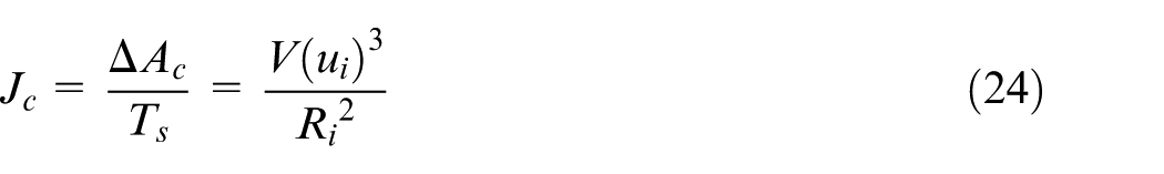
If the motion meets the acceleration limit Jmax, equation (24) can be rewritten as
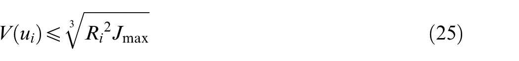
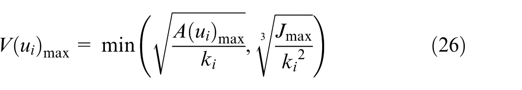
Let ki be the curvature of surface segment ui, then, the maximum feedrate V(ui)max should meet the minimum value between the centrifugal acceleration limit in equation (18) and the centrifugal jerk limit in equation (25)
Chord error constraint
To ensure the geometric accuracy, the chord error must be limited, as shown in Figure 3.
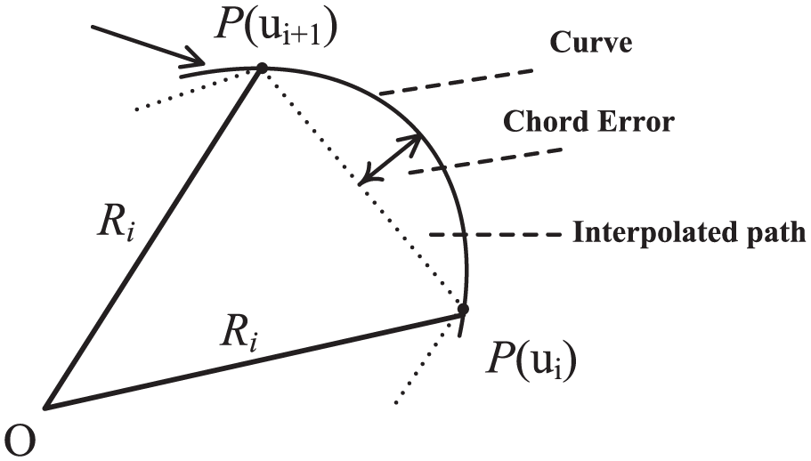
Chord error constraint.
According to the interpolation principle, the chord error in surface ui is expressed by
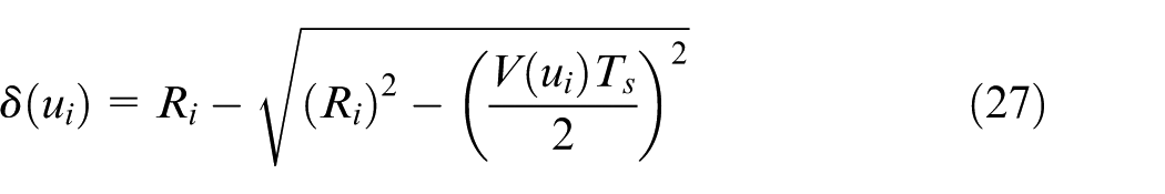
For a given chord error limit δmax, and assuming the Ri is equal to 1/ki, the feedrate is also constrained by
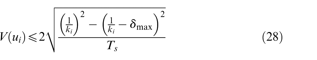
Neglecting the second-order small qualities, equation (28) can be further simplified as
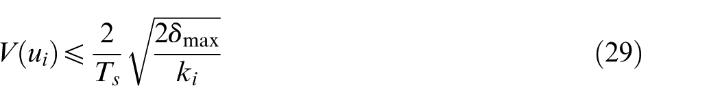
Therefore, based on the surface property, considering the above constraints, including the chord error δ, the maximum velocity V(ui)max, the maximum acceleration A(ui)max, and the maximum jerk Jmax, V(ui), is determined using the following formula
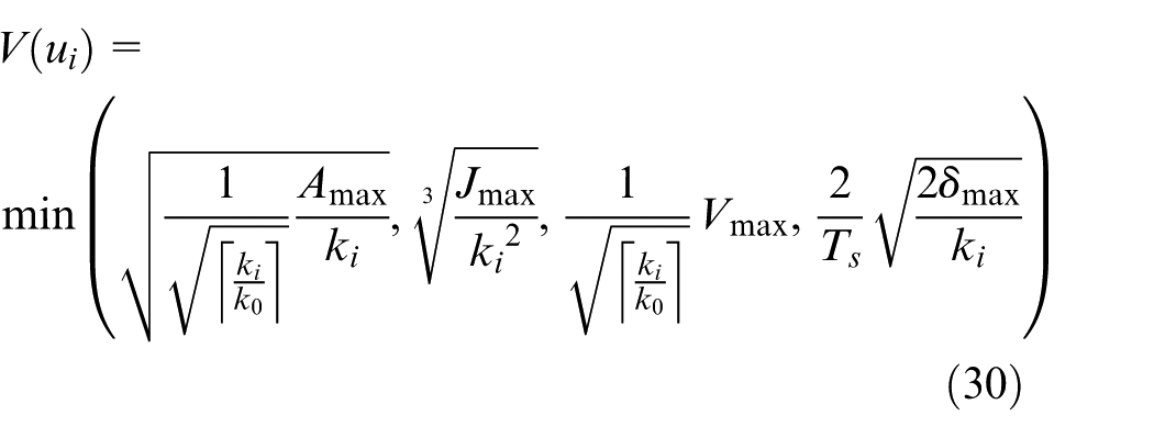
It can be seen from equation (30) that all of the kinematic constraints are related to the surface characteristic. Therefore, the feedrate may change with surface characteristic changes.
Kinematic continuity constraint
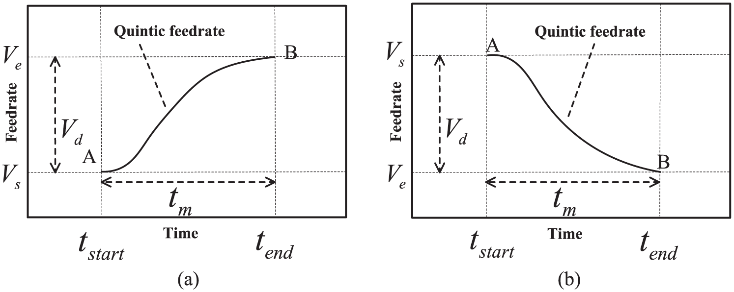
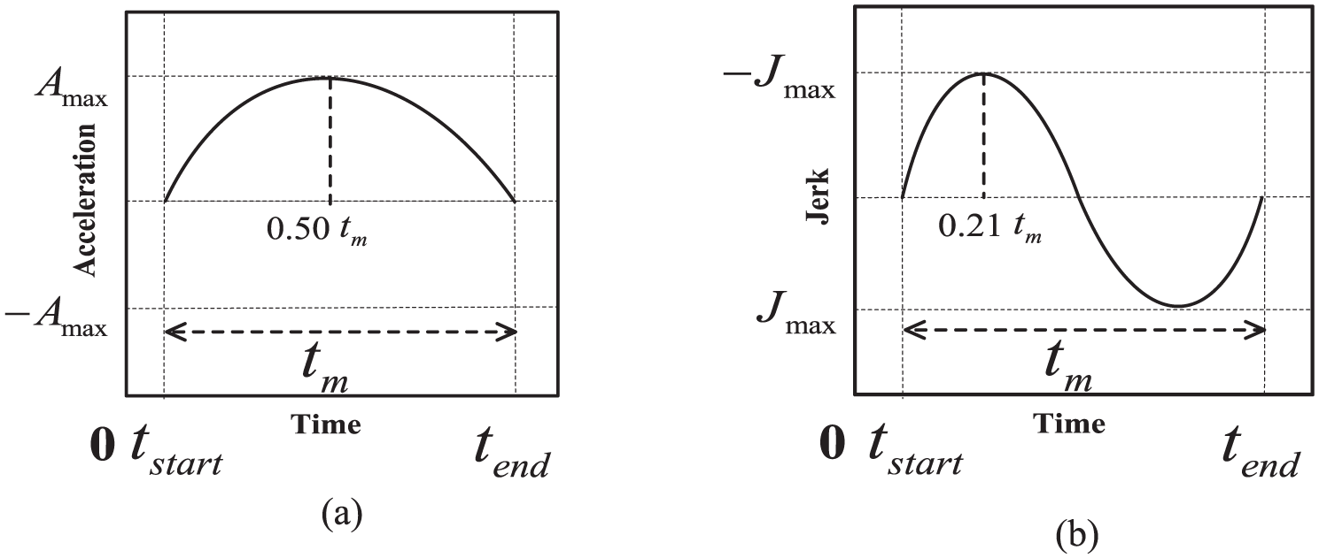
In the process of machining a sculptured surface, if surfaces with jerk discontinuities exist, then the speed along each axis will change abruptly. The acceleration and jerk, the second and third derivatives, respectively, of the feedrate, also change dramatically and may exceed their limits, which can cause undesirable vibration and degrade machining accuracy. To address these problems, the quintic feedrate is proposed, which is shown in Figure 4(a) as a smooth curve. After the first- and second-time derivatives, the four orders of the acceleration profile (shown in Figure 4(b)) and the cubic jerk profile (shown in Figure 4(c)) are obtained.
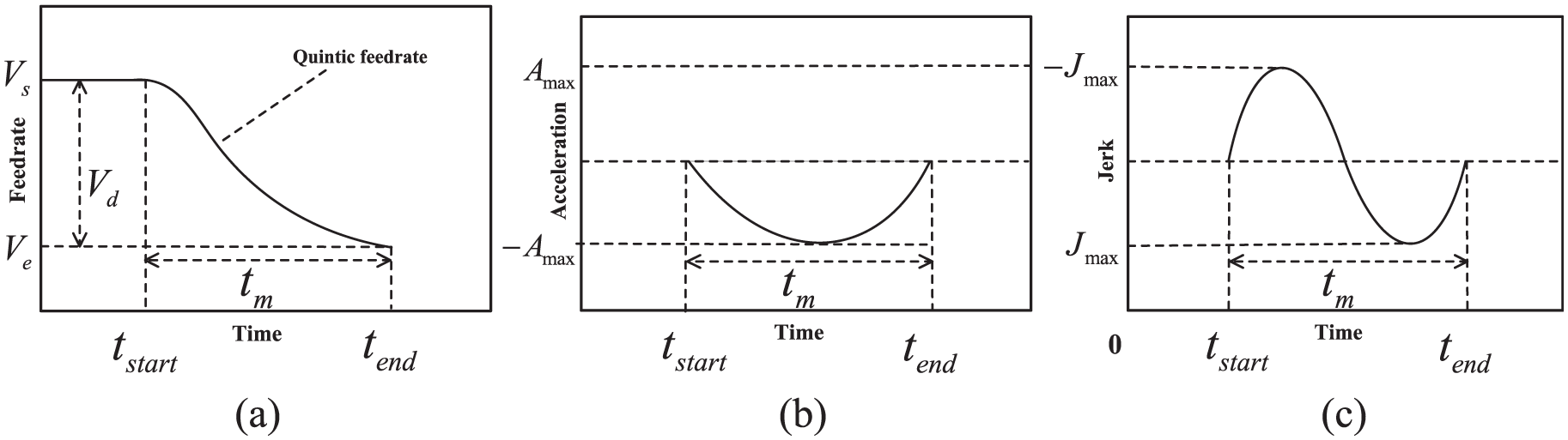
Specifications of quintic federate: (a) feedrate profile, (b) acceleration profile, and (c) jerk profile.
In Figure 4, tstart is the start time, and its corresponding value of feedrate is Vs. Similarly, tend is the finish time, and its corresponding value of feedrate is Ve. In addition, the time difference tm is equal to tend minus tstart, and the feedrate difference Vd is equal to the absolute value of Ve minus Vs. Here, the Vs and Ve are obtained from equation (30) at tstart and tend with the surface curvature ki.
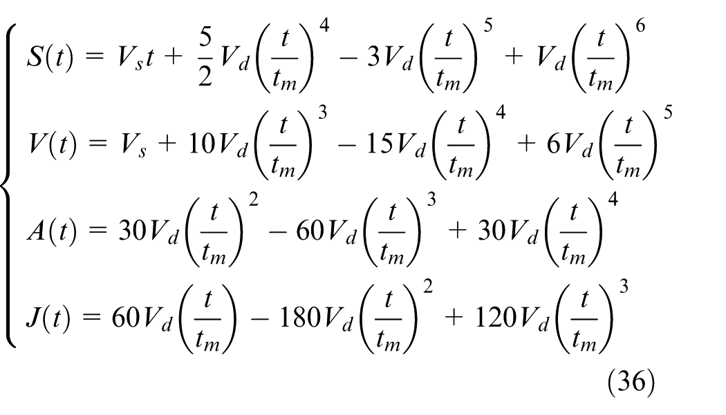
The quintic feedrate is given as

Integrating equation (31) yields the displacement expression
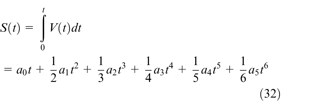
Differentiating equation (31) yields the acceleration equation
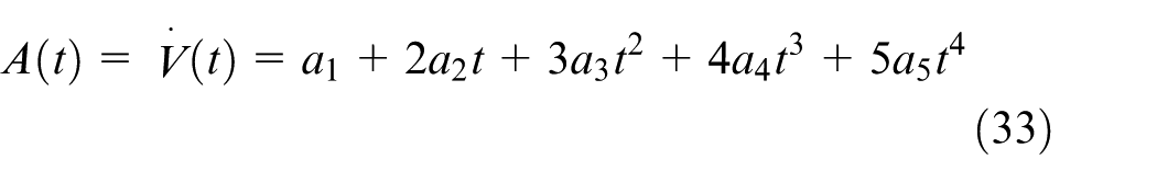
Differentiating equation (33) yields the jerk equation

The coefficients a0, a1, a2, a3, a4, and a5 can be derived from the following boundary conditions
Finally, after the solution of equation (35) is completed, the equations of displacement, velocity, acceleration, and jerk can be further written as
After completion of the kinematic continuity constraints, the machine tool can smooth the surface with a large curvature to improve the machining surface quality while reducing the impact on the machine tool.
Minimum-time feedrate schedule problem
The minimum-time feedrate optimization problem is defined as the minimization of the total travel time (TΣ) along the entire five-axis toolpath (SΣ) while respecting a set of axis limits. The problem can now be stated more formally as follows
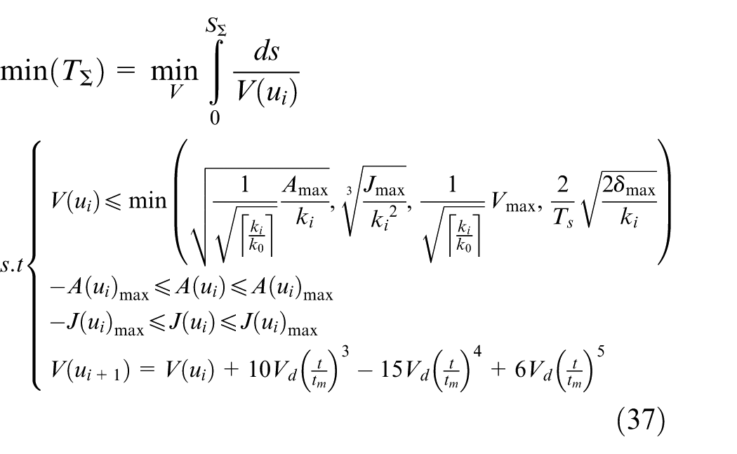
In equation (37), V(ui) is determined such that the total time (TΣ) to execute the entire trajectory is minimal. The constraints specify the system requirements on five axes that must be observed at all times. The minimum-time feedrate optimization problem is then to maximize V(ui) at each path surface ui, so the feedrate trajectory should always be pushed upward at the maximum value without violating the constraints specified by the system requirements.
A novel minimum-time feedrate schedule algorithm
A new ACC/DEC feedrate schedule based on quintic feedrate
The time-optimal problem involves full exertion of the machine tool capability on any axis to reduce machining time as rapidly as possible while meeting the various kinematic requirements. Based on the mentioned quintic feedrate, a new acceleration (ACC)/deceleration (DEC) feedrate schedule with minimum time is proposed, as shown in Figure 5.
Acceleration/deceleration profile: (a) acceleration and (b) deceleration.
To achieve the minimum-time processing time, let
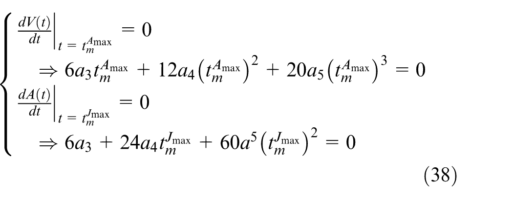
Next,
From Figure 6, the exact solutions of

Exact solution of minimum time: (a) result from the maximum acceleration and (b) result from the maximum jerk.
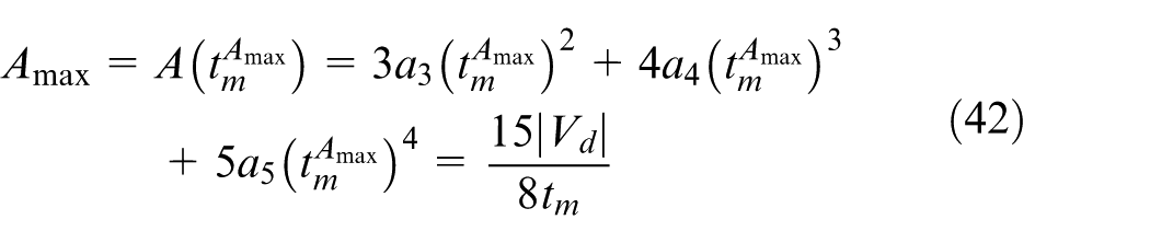
In addition, substituting equations (40) and (41) into equation (36), the maximum acceleration Amax and the maximum jerk Jmax can be obtained as shown in equations (39) and (40), respectively
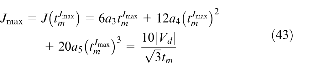
Generally, the acceleration
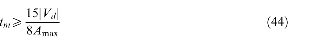
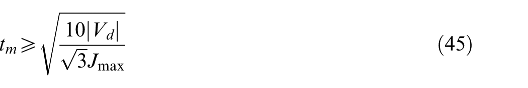
The desired acceleration time tm can be determined by
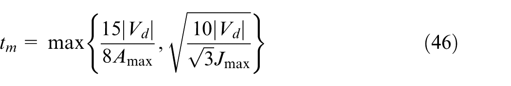
Next, by substituting
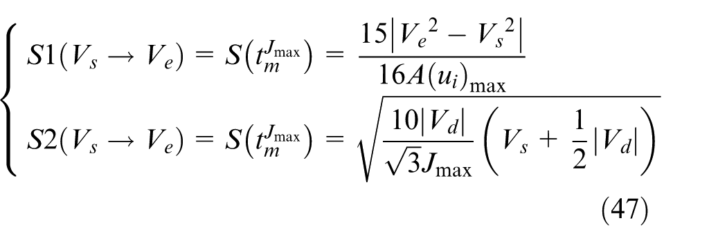
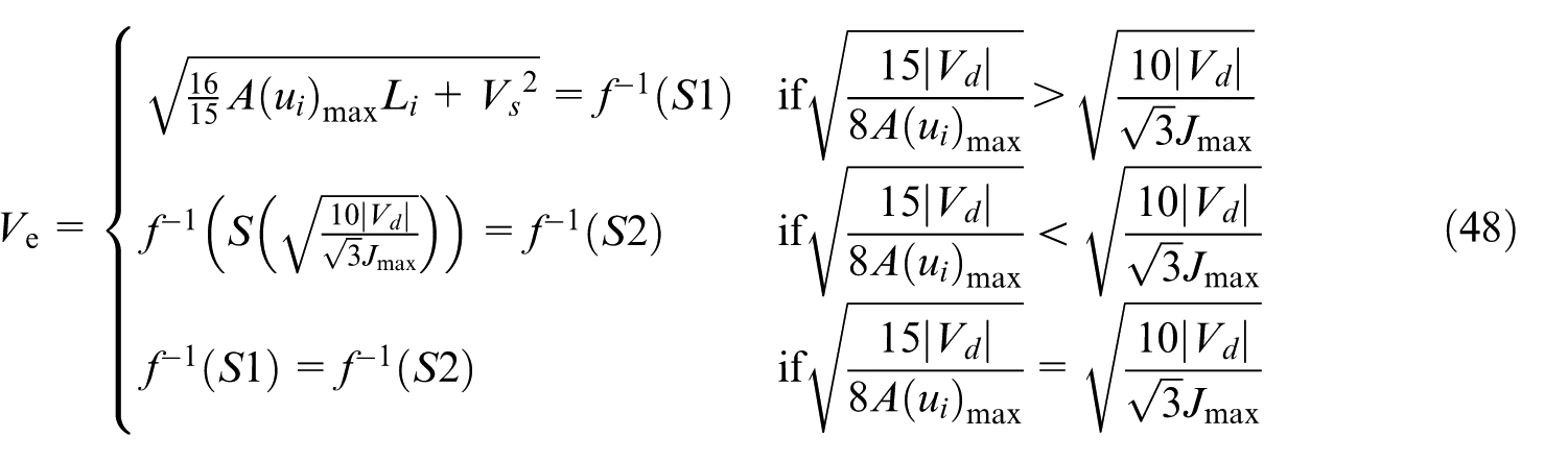
Furthermore, if the start feedrate Vs, the feedrate difference Vd, the length Li, and the maximum acceleration A(ui)max and Jmax on segment surface ui are known, then the allowable ending feedrate Ve is given as
Therefore, the ACC/DEC feedrate schedule based on the quintic feedrate is realized. It not only guarantees the feedrate, acceleration, and jerk continuity but also shortens the machining time by exerting the machining capability on any axis.
Minimum-time feedrate schedule algorithm
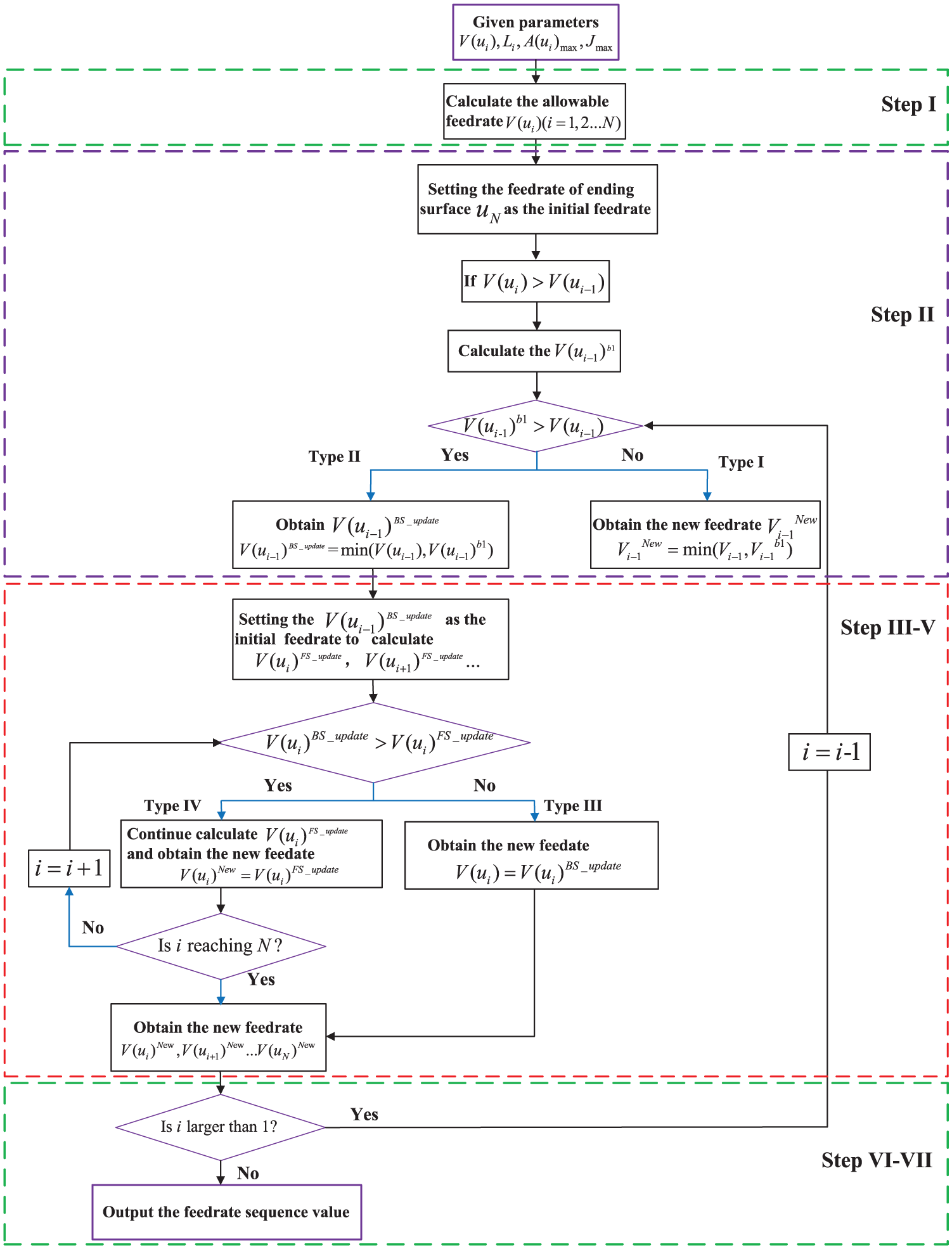
Although the new ACC/DEC schedule can achieve the minimum time, it may not meet the deceleration requirements or kinematic parameter continuity along the entire five-axis toolpath. To address these problems, the minimum-time feedrate schedule can be implemented by bidirectional feedrate schedule algorithm (BFSA). The objective of BFSA is to reduce the total time and obtain the optimal feedrate based on a quintic velocity profile while respecting various types of constraints. Its basic structure mainly involves forward schedule and backward schedule,29,30 and its details are summarized as follows.
Step I
Considering the mentioned constraints, the allowable feedrate
Step II
Once Step I is completed, the Backward schedule, which is based on minimum-time ACC/DEC feedrate schedule strategy, is implemented from the end (i = N) to the start (i = 1) of the toolpath. The velocity of the ending surface is set to be the initial velocity. According to equation (48), the value of V(ui−1)b1 can be obtained.
Taking V(ui) larger than V(ui−1) (DEC) as an example, there are two types shown in Figure 7 (the black curve shows the motion direction from ui to ui−1, and their corresponding times for ui and ui−1 are tstart and tend, respectively):
Type I: If V(ui−1)b1 is smaller than V(ui−1), as shown in Figure 7(a), then the machine tool has enough capability to reduce the feedrate from V(ui) to V(ui−1) with minimum time. Thus, the feedrate of segment surface ui−1 should be updated by the minimum between V(ui−1)b1 and V(ui−1), which is defined as V(ui−1)BS_update. At this point, the process goes to Step VI.
Type II: If V(ui−1)b1 is larger than V(ui−1), as shown in Figure 7(b), then the capability of machine tool is not sufficient to reduce the feedrate from V(ui) to V(ui−1) within the minimum-time period. Thus, the feedrate of segment surface ui−1 should be updated by the minimum between V(ui−1)b1 and V(ui−1), which is also defined as V(ui−1)BS_update. At this point, the process goes to Step III.
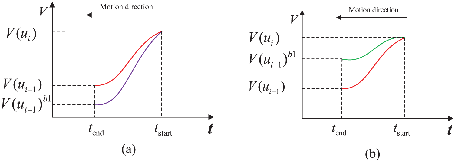
Types of Backward Scheduling in the DEC section: (a) Type I and (b) Type II.
Step III
After Backward Schedule, the new feedrate V(ui−1)BS_update could be derived from min(V(ui−1)b1, V(ui−1)).
Because of the limit of length and machining time, it is necessary to stop at segment surface ui−1, and its corresponding feedrate V(ui−1)BS_update is set to the starting one to recalculate V(ui)FS_update (obtained from equation (48)) in surface segment ui. The updated feedrate in surface segment ui is defined as V(ui)new, and its value is equal to the minimum between V(ui)FS_update and V(ui)BS_update.
Note that if V(ui)FS_update is larger than V(ui)BS_update, then the forward schedule should be stopped.
Taking the surface segments ui−1, ui, and ui+1 as an example, if V(ui+1)FS_update is larger than V(ui+1)BS_update, which is defined as Type III, as shown in Figure 8(a) (the arrow shows the movement direction), it signifies that the machine tool has enough capability to reach V(ui+1)BS_update. At this point, the forward scheduling can be stopped to reduce the amount of calculation. Otherwise, if V(ui+1)FS_update is smaller than V(ui+1)BS_update, which is defined as Type IV, the process goes to Step IV.
Step IV
If i < N, then set i = I+ 1, the forward schedule should be stopped when V(ui+k)FS_update is larger than V(ui+k)BS_update (1 < k < N – i), as shown in Figure 8(b) (the arrow shows the movement direction). Otherwise, continue.
Step V
If i = N, then the forward schedule is stopped, and the process goes to Step VI.
Step VI
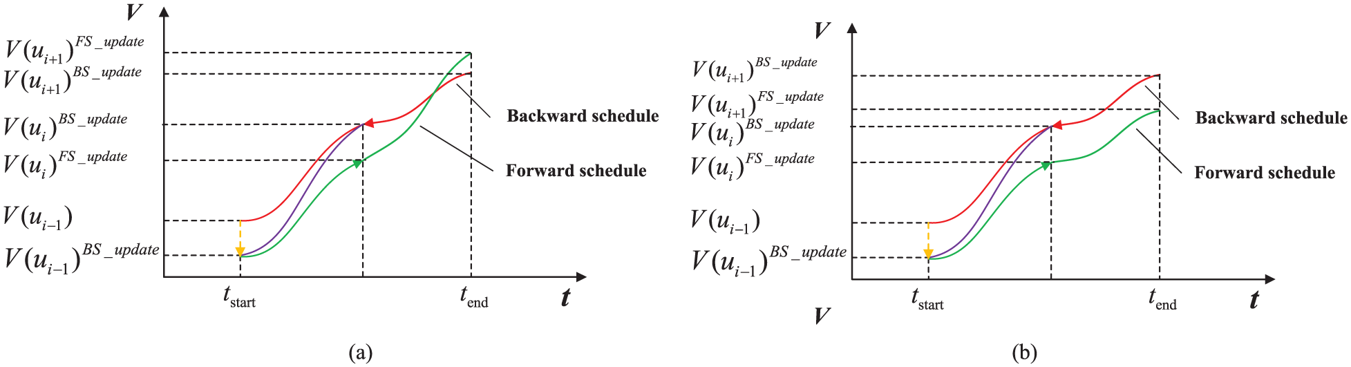
Types of Forward Scheduling: (a) Type III and (b) Type IV.
After the completion of forward schedule in surface ui, if 1 < i, then set i = i– 1, and the backward schedule should continue and go to Step II. Otherwise, continue.
The process of Step VI (suppose the feedrate of the last point is equal to zero) is shown in Figure 9.
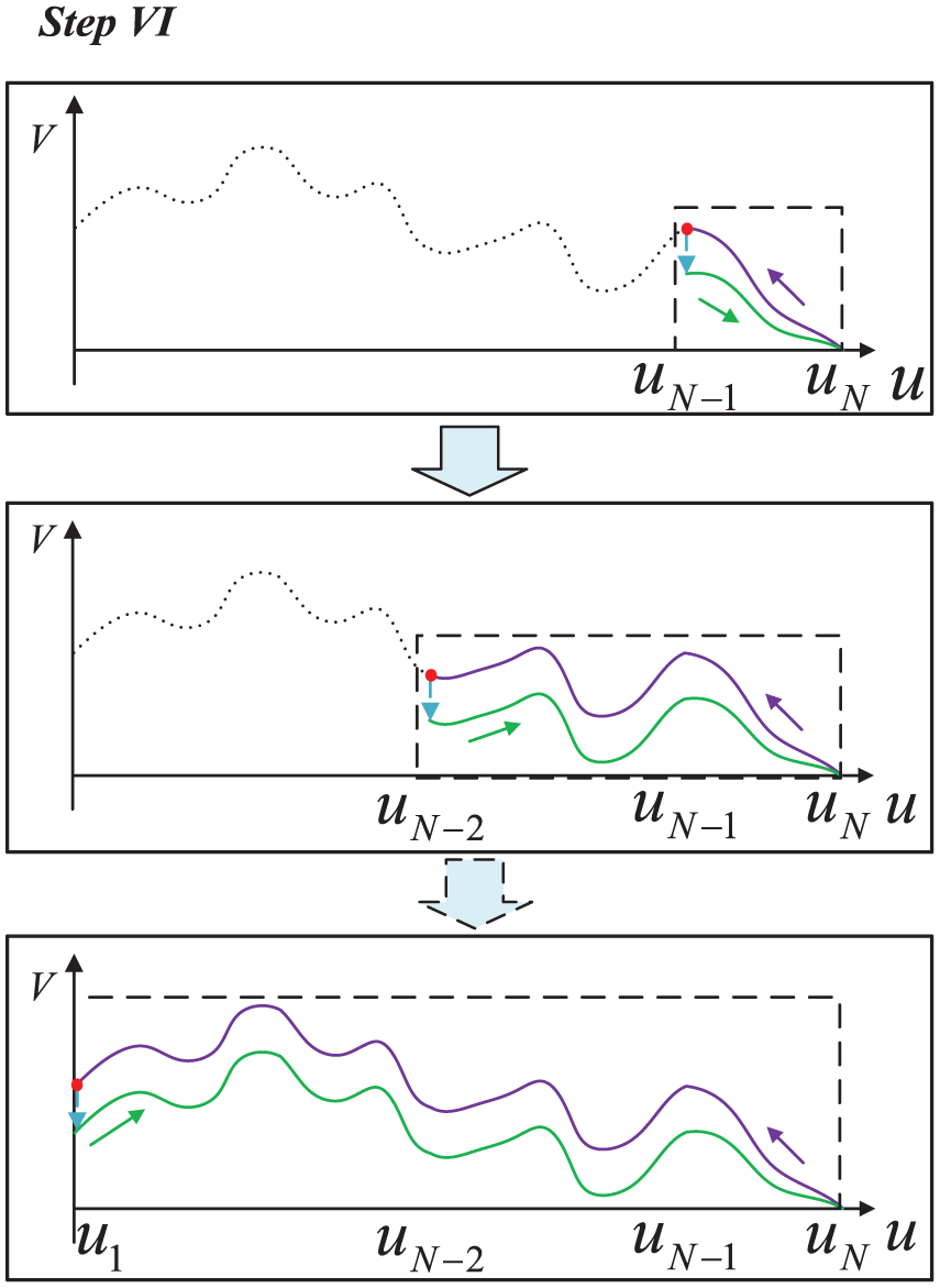
The process of Step VI.
Step VII
If i = 1, then exit the BFSA and output the new feedrate sequences
Taking the DEC as an example, the whole flowchart of BFSA is listed in Figure 10. After the BFSA, the new feedrate sequences of the whole surface can be updated with minimum time while respecting contour error, feedrate, centripetal acceleration, and jerk limits on any axis. This not only reduces the machining time but can also guarantee the continuity of the jerk profile, which is conducive to improve machining efficiency and machining quality.
BFSA flowchart of the DEC.
Simulation and experimental results
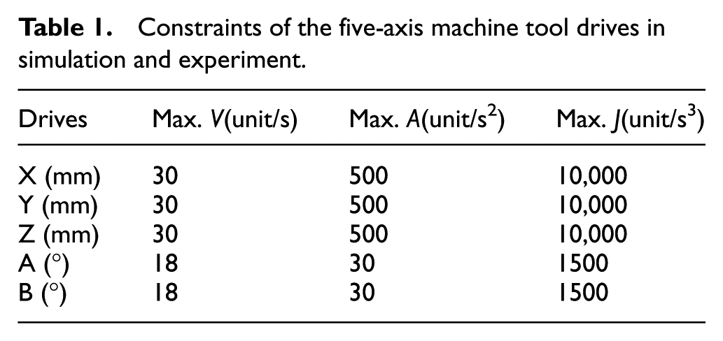
In this section, to verify the proposed feedrate schedule method, a desirable test specimen is adopted, and the S part is shown in Figure 11(a). It can be seen that the shape of the S part appears similar to the letter “S,” but it is totally different. It is composed of two B-spline curves that are developed into the surface. Furthermore, to date, the S part presents multiple features of the sculptured surface with variable curvature, 25 as shown in Figure 11(b). In simulations and experiments, the S part is implemented on the AB-type five-axis machine tool, and the constraints of the machine tool drives are arranged according to Table 1.
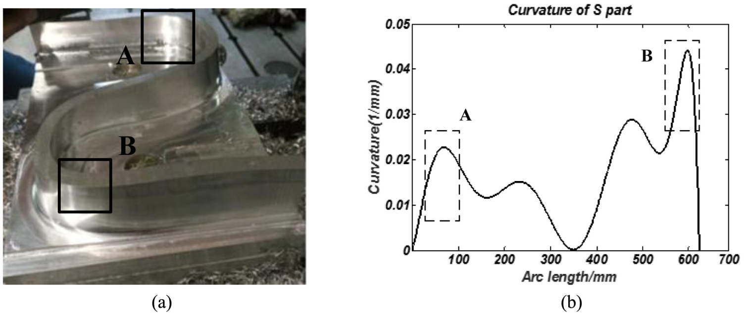
Specification of S part: (a) S part and (b) curvature profile.
Constraints of the five-axis machine tool drives in simulation and experiment.
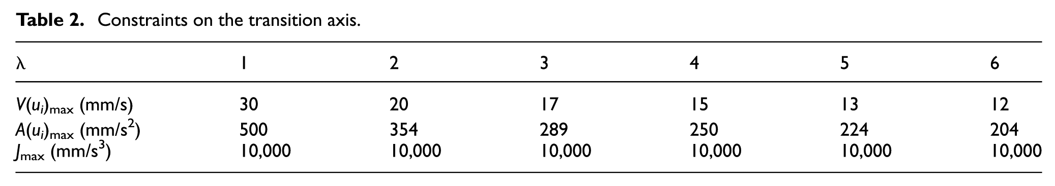
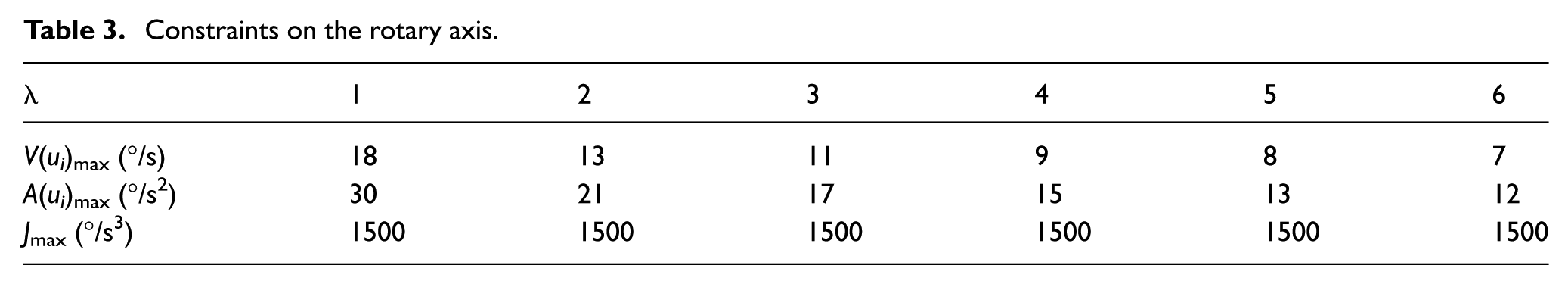
According to the “Maximum feedrate and acceleration constraint” section, as the curvature changes, the maximum speed is constantly changing. In this section, combined with the performance of machine tool, the line reference curvature k0 and the maximum chord error δmax are set to 0.008 and 0.5 µm, respectively. Moreover, the values of λ and m are also changing with the change of curvature. Therefore, the constraints on the transition axis and rotary axis in the sculptured surface are shown in Tables 2 and 3.
Constraints on the transition axis.
Constraints on the rotary axis.
To validate the effectiveness of the presented method, the traditional feedrate schedule algorithm, S-shaped acceleration and deceleration (S-shaped ACC/DEC), is adopted to machine S part. For machining the S part, the feedrate schedule results of the S-shaped ACC/DEC and BFSA are given in Figure 12. It can be seen that when the machine is given a command feedrate F = 1200 mm/min, the feedrate in the small curvature surface still remains lower, as apparent at the arc length 300–400 mm shown in Figure 12(a). Thus, although the feedrate does not violate the limits, the machine tool capability may not be fully exerted and it may lead to reduction of the machining efficiency.
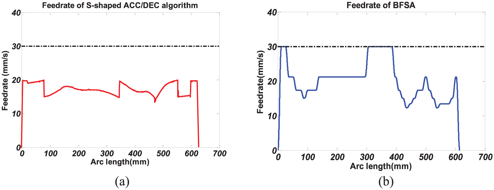
Feedrate profiles: (a) S-shaped ACC/DEC and (b) BFSA.
For BFSA, combined with the S part curvature distribution in Figure 11(b), the BFSA fully exerts the machine tool capability, as shown in Figure 12(b). When the curvature is relatively large, the feedrate is relatively small to guarantee machining quality. For the surface with small curvature, such as the arc length 300–400 mm, the feedrate reaches its limit as soon as possible to improve efficiency under the chord error constraint. In addition, for the surfaces with larger curvature, such as the arc lengths 50–100 and 500–600 mm, the feedrate of BFSA is lower than that of the S-shaped ACC/DEC, thereby improving machining accuracy.
In terms of processing efficiency, using the traditional feedrate schedule, the machining time is 36.28 s. Compared with the traditional feedrate schedule S-shaped ACC/DEC, the machining time of BFSA is shorter, that is, 24.63 s, corresponding to a 32.11% increase in productivity. Therefore, in the machining efficiency, the BFSA is also better than the traditional feedrate schedule algorithm, which can fully exert the five-axis machine tool capability.
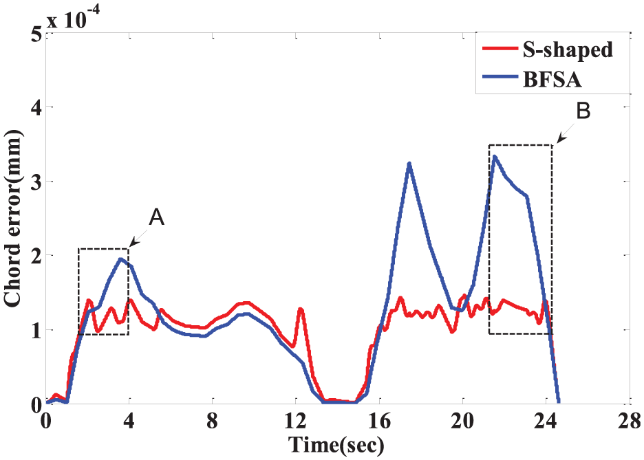
Figure 13 depicts the changes of chord error in the feedrate optimization process. The chord errors are lower than the allowable value. Especially in A- and B-sections, the chord error of BFSA is lower than that of S-shaped as the feedrate of BFSA is lower than that of S-shaped, as shown in Figure 12, which is conducive to improve machining quality. In contrast, the chord error of BFSA is higher than that of S-shaped between 6 and 16 s, because the feedrate of BFSA is higher than S-shaped, which can help to improve machining efficiency.
Chord error.
In addition to the kinematic parameter continuity, although the S-shaped ACC/DEC algorithm does not exceed the axis limits, it can be seen from Figure 14 that the feedrate drops dramatically in a surface of high curvature, such as the A-section (as shown in Figure 14(a)) and B-section (as shown in Figure 14(b)). In these sections, as the feedrate changes sharply, the acceleration and jerk may also change dramatically, thereby inducing impact and consequently reducing machining quality. For BFSA, Figure 15 shows that in the surface with high curvature, such as A-section (as shown in Figure 15(a)) and B-section (as shown in Figure 15(b)), the feedrate continuity can be ensured and the machine tool can process these surfaces with a small amount of chattering. Meanwhile, the feedrate continuity can be ensured and the machine tool can process these surfaces with a small amount of chattering. Therefore, in terms of feedrate continuity, the BFSA is also better than the traditional feedrate schedule method.
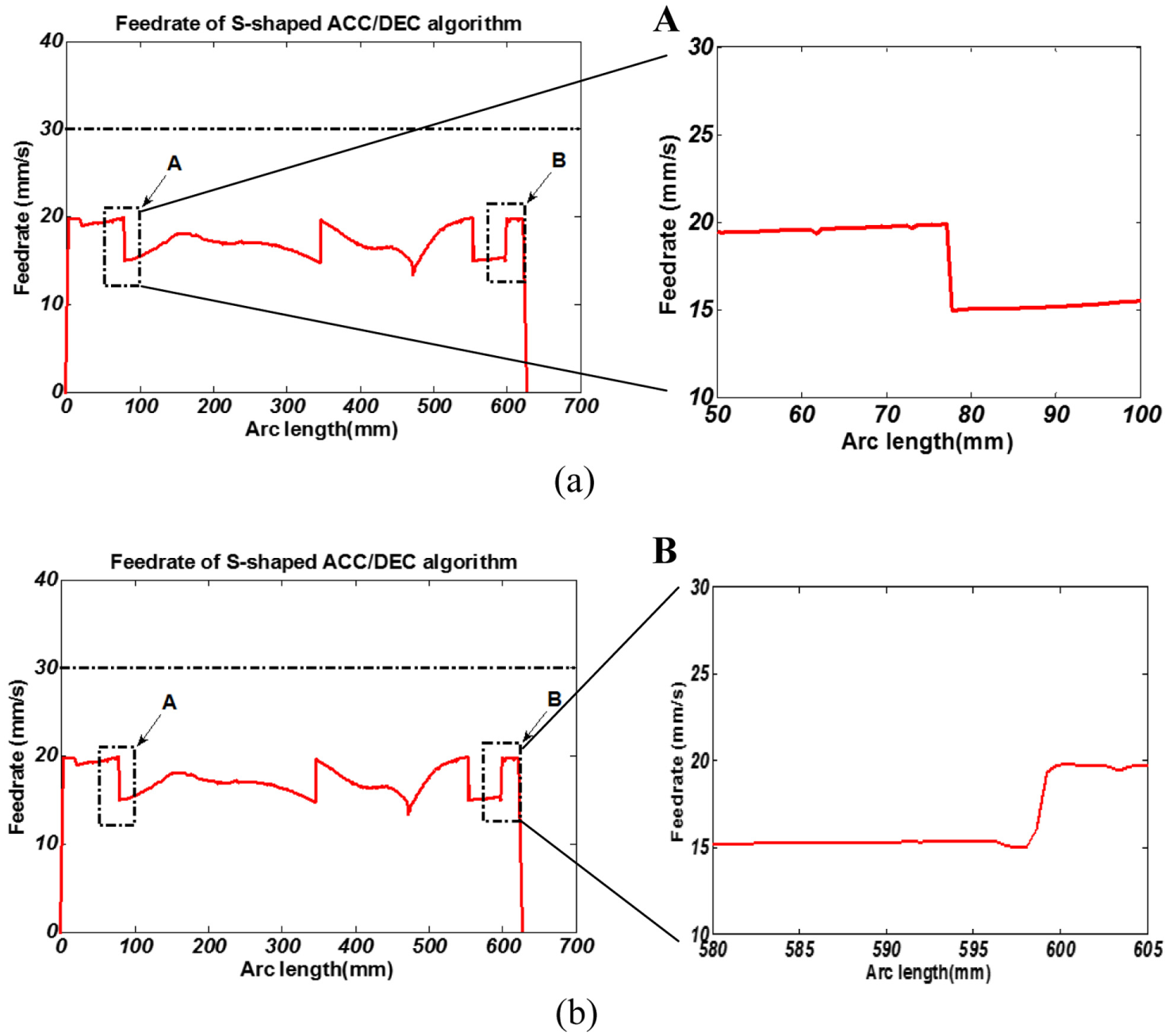
Traditional feedrate schedule method: (a) A-section and (b) B-section.
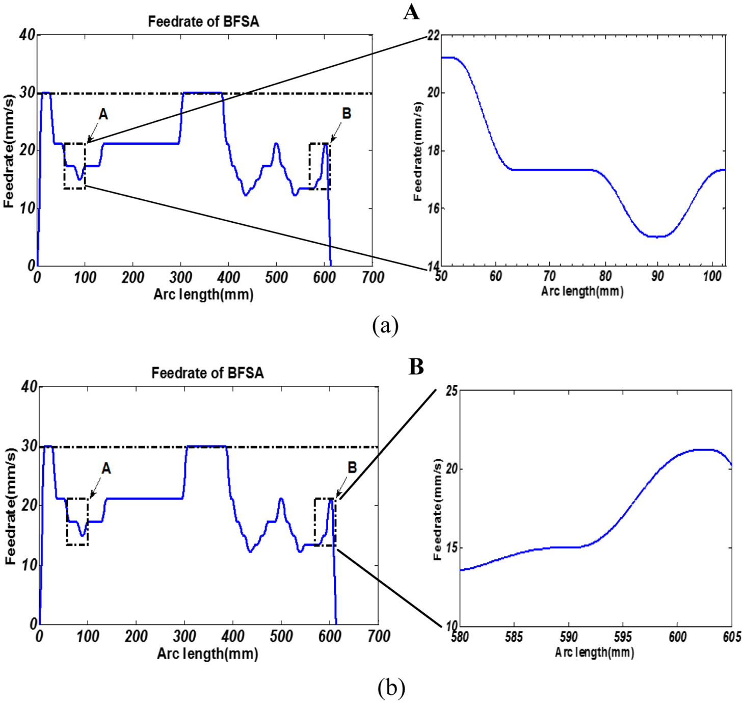
BFSA feedrate schedule method: (a) A-section and (b) B-section.
The surface quality of S part after machining in regions A and B is shown in Figures 16 and 17, respectively. It is obvious that the surface quality machined by the proposed method BFSA is better than the traditional S-shaped ACC/DEC method at A- and B-sections because BFSA can pass the large curvature surface with lower feedrate and guarantee the feedrate continuity. Furthermore, compared with S-shaped algorithm, the BFSA avoids the cutting mark, which also makes the machining quality better.
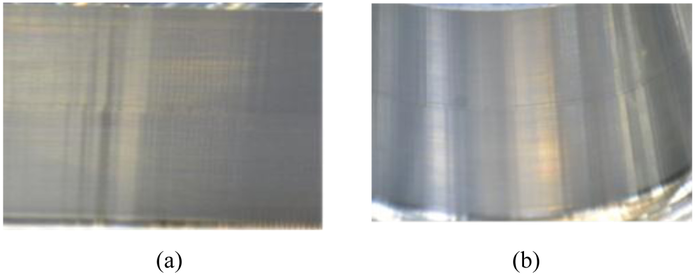
Comparison of surface quality of two methods at region B: (a) S-shaped algorithm and (b) BFSA.
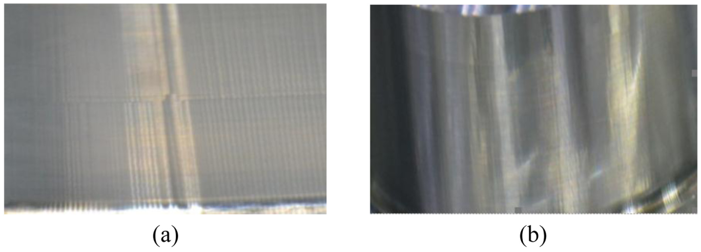
Comparison of surface quality of two methods at region A: (a) S-shaped algorithm and (b) BFSA.
In addition, the profile of velocity, acceleration, and jerk of transition axes and rotary axes is also obtained. As shown in Figure 18(a) and (b), they respectively show the velocity curves of transition axes and rotary axes, it can be seen that the velocities of two types of drive axes are all confined on the given limits in Tables 2 and 3 along the entire toolpath. All velocity curves are smooth and change gradually. Figure 19(a) and (b) demonstrates that the accelerations of transition axes and rotary axes are all confined within the allowable range in Tables 2 and 3, respectively. All the acceleration curves are smooth and change steadily. In addition, Figure 20(a) and (b) show that the jerk of two type axes are all limited on the given value [−10,000 mm/s3 10,000 mm/s3] and [–1500 mm/s3 1500 mm/s3], respectively. From the results, it indicates that the proposed method can guarantee the continuity and smoothness of jerk curves, which can greatly improve machining quality. The results on any axis illustrate the feasibility of the proposed feedrate schedule method and the ability to achieve the good feedrate, acceleration, and jerk profile with various constraints.
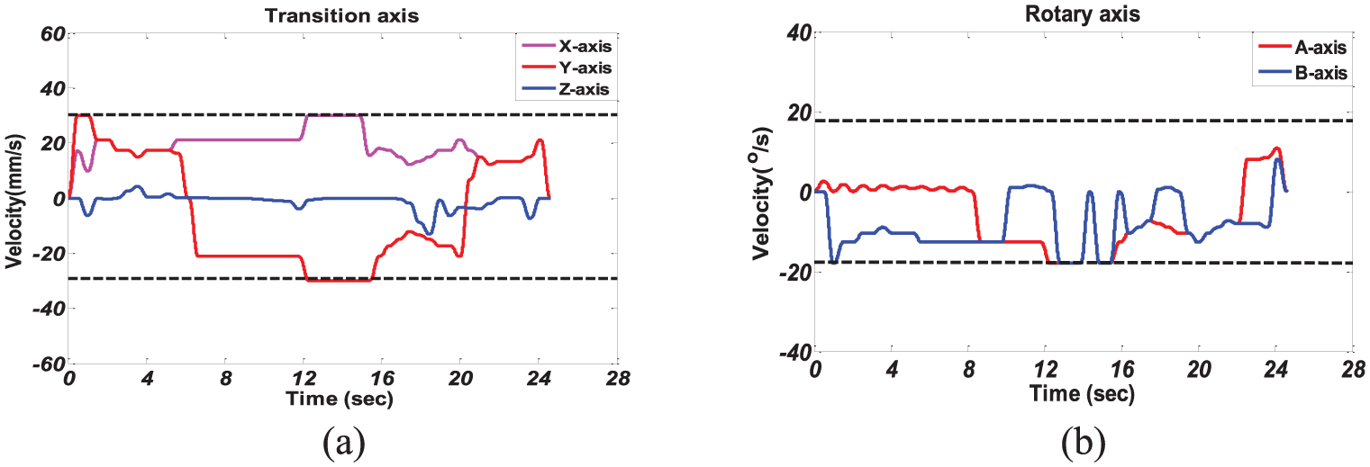
Feedrate profile of BFSA: (a) transition axis and (b) rotary axis.
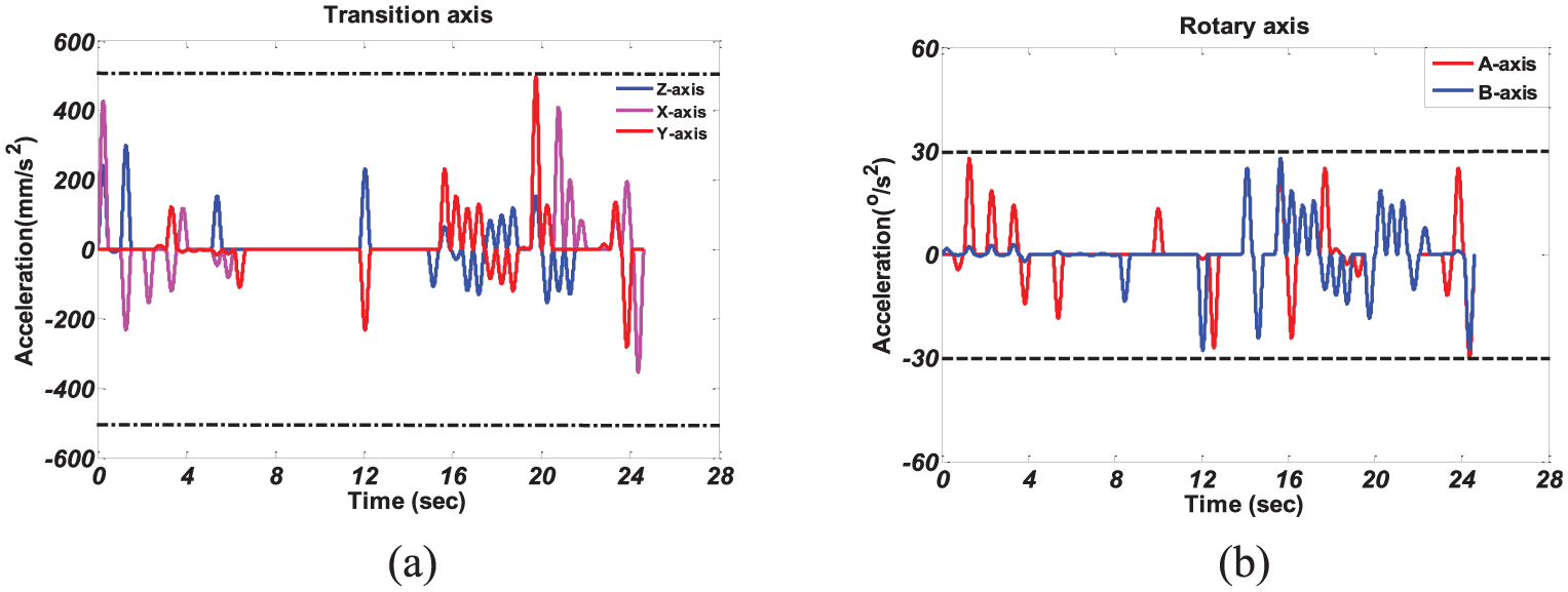
Acceleration profile of BFSA: (a) transition axis and (b) rotary axis.
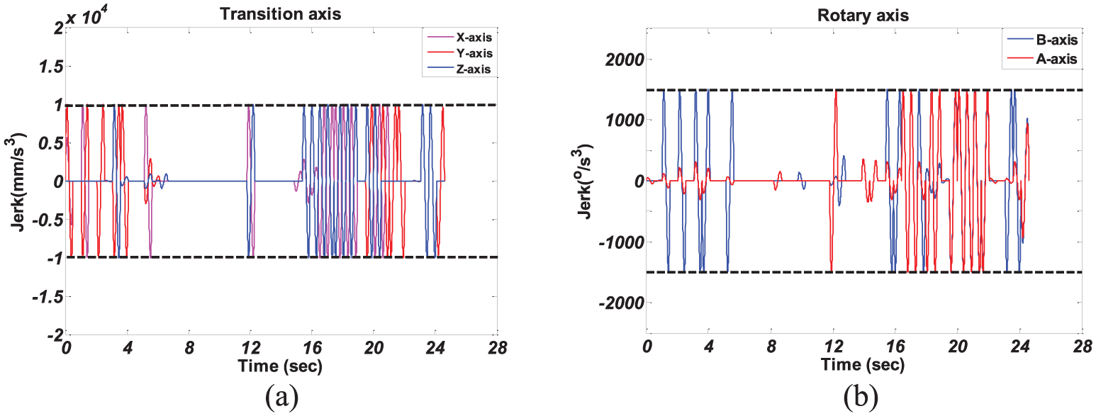
Jerk profile of BFSA: (a) transition axis and (b) rotary axis.
Conclusion
Sculpture surface, due to the complex geometry, can be seen as a challenge to demonstrate the machine tool capabilities. The traditional methods for sculptured surface machining usually set a constant and lower feedrate along the entire toolpath to avoid excessive requirements in large curvature surface. However, the influence of characteristics of the sculpture surface on kinematical planning and the cutting accuracy are still unknown. This article proposed a novel feedrate schedule method to improve the machining efficiency for the five-axis machine tool. Based on the results of tests using the proposed methods, the following conclusive remarks are given:
The new constraint conditions are derived based on the sculptured surface characteristic. The mechanism between the maximum value of kinematic parameters and surface characteristic is established by analyzing the following error on each axis, and the geometric error constraint and quintic feedrate continuity restrictions are included into the constraint conditions.
A novel minimum-time feedrate schedule is proposed. Based on mentioned constraints, a new ACC/DEC feedrate schedule method is developed to achieve the minimization of machining time in adjacent surface segments. On this basis, a novel minimum-time feedrate schedule method by BFSA is presented. Through the backward and forward schedules in iterative process, both the scheduled feedrate and minimum processing time are obtained simultaneously along the entire toolpath without exceeding the systematic constrains.
The proposed method is validated by simulation and experimental results. Compared with the existing S-acceleration/deceleration method, the proposed method realizes the smoothness of feedrate, acceleration, and jerk, especially in some surface with large curvature, which is conducive to improve machining quality. In addition, the processing efficiency of proposed method is also better than that of traditional method. The experimental results demonstrate that the total processing time of BFSA drops to 24.63 s, compared with 36.28 s of S-shaped algorithm, resulting in 32.11% increase in productivity.
Footnotes
Declaration of conflicting interests
The author(s) declared no potential conflicts of interest with respect to the research, authorship, and/or publication of this article.
Funding
The author(s) disclosed receipt of the following financial support for the research, authorship, and/or publication of this article: This work is supported by the National Natural Science Foundation of China (Grant No. 51205048) and the Fundamental Research Funds for the Central Universities (Grant No. ZYGX2016 J109).