
Abstract
Gap width is an important factor that affects material removal rate, surface finish, and machining stability in electrical discharge machining processes. This research is to develop a novel control method for a new hybrid positioning system which consists of a linear motor and a piezoelectric actuator for high-efficiency electrical discharge machining processes. In the new system, the linear motor provides the macro feeding while the piezoelectric actuator feeds the workpiece in micro scale at high frequency. To reduce the delay caused by separate movements of the linear motor and piezoelectric actuator, a new control algorithm was developed to synchronize the movements of the motor and piezoelectric actuator. A fuzzy control system was used to control the feeding process. Piezoelectric actuator position and its speed were selected as the fuzzy inputs, while the fuzzy output was the linear motor speed. Cutting experiments were conducted, and results show that the fuzzy system is more powerful than the conventional algorithm and the new algorithm with constant motor speed. An increase in material removal rate of 1.6 times was achieved using the proposed fuzzy control algorithm.
Introduction
Diamond is the hardest material in the world. Owing to the ultra-hardness and exceptional wear resistance of polycrystalline diamond (PCD), cutting tools made of PCD are extensively used in the aerospace, biomedical, and manufacturing industry to machine turbine blades, medical implants, and difficult-to-machine materials such as titanium alloys.1–3 However, the machining efficiency of conventional abrasive grinding is very low in fabricating PCD tools because of the hardness of diamond particles sintered inside the PCD. One of the most effective techniques to machine PCD materials in industry is electrical discharge grinding (EDG), which is a type of electrical discharge machining (EDM) method with a rotating wheel electrode. 4 EDG overcomes the most common problems in the traditional grinding process, such as tool wear, significant grinding force, and low material removal rate (MRR). However, maintaining a favorable spark gap is still an extremely difficult task because EDG is also a stochastic process which is affected by multiple interactive independent parameters.5,6 The stability of the machining process is negatively affected by the abnormal discharge pulses and the accumulation of debris in the gap which is a result of unstable gap distance. 7 Therefore, keeping a constant gap distance is critical in achieving a stable and efficient EDM process.
To feed the workpiece in the EDM process, although different actuators have been used, for example, linear servo motor, DC motor, and stepper motor,5,8 the need for more accurate and fast actuators is continuously increasing due to the very small spark gap which is in the range of 20–50 µm and the high frequency change in working conditions in the gap. The piezoelectric actuator (PZT) is one of the most suitable actuators because of its high precision and high response frequency. 9 However, a feeding system consisting only of a PZT is not able to meet practical requirements because the working range of PZT is usually very short. An EDG process should not only have high frequency response but also a long working range. A hybrid dual-stage feeding mechanism which consists of a servo motor to satisfy the long-range requirement and a PZT to realize high frequency response was recently developed by Hu et al., 10 and a PZT combined with a stepper motor was developed by Kumar et al. 11 in a parallel spark micro-electrical discharge machining (micro-EDM). Using a PZT in dual-stage feeding system could theoretically increase the EDM machining speed, but the control of the two components which are moving at the same time is a challenging problem in optimizing its performance. Different algorithms have been developed to control the simultaneous movements of the linear motor and the PZT. For example, Kunieda et al. 12 built a simulator in order to investigate the effects of using PZT on the machining speed and stability. The PZT was used to respond to the machining process, and the linear motor was to keep a dynamic range of the PZT to around 16 µm, but it was unclear how both actuators were controlled to perform the required tasks. Tong et al. 13 used a novel algorithm by stopping the PZT when the linear motor was moving. This method did increase the machining speed, however, because the PZT and the linear motor could not move simultaneously; the time was still wasted when the PZT actuator paused for the linear motor to move to compensate the distance after the PZT reached its full range. Zhu et al. 14 used the PZT as a capacitor to adjust the discharge gap based on inverse piezoelectric effect; the feeding process was dependent on the charging and discharging of PZT and the external adjustable capacitor. Once the discharge happened, the PZT would retract and it would move forward again after the capacitors charge. This process could increase the stability of the process by preventing the occurrence of arc and short circuit; however, it was unable to ensure that enough power was delivered to the gap to complete the machining process. In order to achieve both large stroke and high response frequency, Huang et al. 15 used a PZT as a micro-driven system which was mounted on a macro-driven table for macro steps. However, due to the short range of PZT, in case of arcing, the retract distance was not sufficient to eliminate the detrimental spark status.
In order to solve these problems, a new algorithm was developed in this article to drive the dual-stage mechanism which consists of a linear servo motor and a PZT. In this system, the linear motor was responsible for long travel distance, while the PZT was responsible for fast feeding. The new control strategy of macro–micro feeding was to obtain the highest machining efficiency. Experiments were conducted to validate the effectiveness of the new system by measuring the machining speed. The new algorithm resulted in an increase of 150% in machining speed in comparison with the conventional one, and the fuzzy control system was proved to be a more powerful dual-stage feeding mechanism, which was 160% faster than the traditional control methods with the conventional algorithm.
Fuzzy systems in EDM
Fuzzy logic was invented by Lotfi Zadeh in the 1960s. It combines the concepts of crisp logic and the Lukasiewicz sets by defining graded membership. One of the advantages of fuzzy logic is using mathematics to link language and human intelligence. Many concepts are better defined by words than by mathematics; fuzzy logic and its expression in fuzzy sets provide a discipline that can construct better models of reality.16,17 Fuzzy logic theory can easily capture the approximate and qualitative aspects of human knowledge and perform reasoning and has been proved to be a reliable method which has been successfully applied to the control of adaptive and nonlinear systems.5,18–20
The EDM process can be controlled through different parameters including gap voltage,21,22 gap current, short-circuit ratio, and open-circuit ratio. In addition, pulse discrimination, delay time, and on and off time are critical variables that affect the performance of EDM processes.23,24 EDM process is a complicated, stochastic, nonlinear, and time-variant process that makes the traditional control methods inefficient, and the need for new and intelligent methods is a growing challenge. In order to control the EDM process, various new control methods have been proposed using fuzzy logic for gap monitoring and pulse classification.25,26 Gap current and voltage were converted into fuzzy sets, then fuzzy rule-base was built based on the human knowledge. 27 Using time series of gap status like ignition delay time, new methods for pulse discrimination have also been proposed.6,28,29
The commonly used gap controllers are built based on the average gap voltage. The gap voltage is measured over a short period, and the average value is calculated and compared to a reference value to compute the error signal that feeds back to the controller. Based on the error signal, the controller calculates the required axial feedrate to maintain the optimum gap distance. 28 A tunable fuzzy logic–based servo controller for monitoring and control of the micro-EDM was developed by Byiringiro et al. 30 using gap voltage and gap current of the discharge pulses as the control components; the simulated results showed that fuzzy control did improve the performance of the micro-EDM.
A high-speed EDM monitoring system was implemented to measure the gap voltage, current, and ignition delay time by Kao et al. 28 to derive three input parameters—the average gap voltage, deviation in spark ratio, and change in the deviation in spark ratio. The adaptive fuzzy logic control was integrated with piezoelectric fast-tool servo for a more robust and efficient micro-hole EDM process, which can greatly reduce the cycle time and cost. Using a PZT to feed the workpiece table in a micro-hole EDM and a DC servo motor for the tool feeding, they used an adaptive fuzzy logic controller and found that the system was more stable and efficient. However, due to the synthesis capability of the controller, displacement less than 5 µm became unreachable, and the system cannot respond to such small displacement; therefore, it reduced the system capability.
Using short-circuit ratio (the proportion of short circuits in the total sparks), an adaptive fuzzy control system was proposed for servo feed control by Yan. 31 The short-circuit ratio was controlled at pre-determined level by another fuzzy logic controller using servo voltage for adaptive process control; the experimental results showed that the adaptive fuzzy control improved the stability and machining speed. Servo DC motors, stepper motors, and electromechanical piezo drives have also been applied in recent micro-EDM machines. However, the stable control of the discharge process is difficult to maintain; the development of an effective servo feed control method has become an important and urgent issue in EDM.
New dual-stage control algorithm
The proposed dual-stage feeding mechanism consists of a linear motor as the macro drive and a PZT as the micro drive. The workpiece was held by the PZT. The PZT was mounted on the top of the linear motor which moved in the same direction as shown in Figure 1.
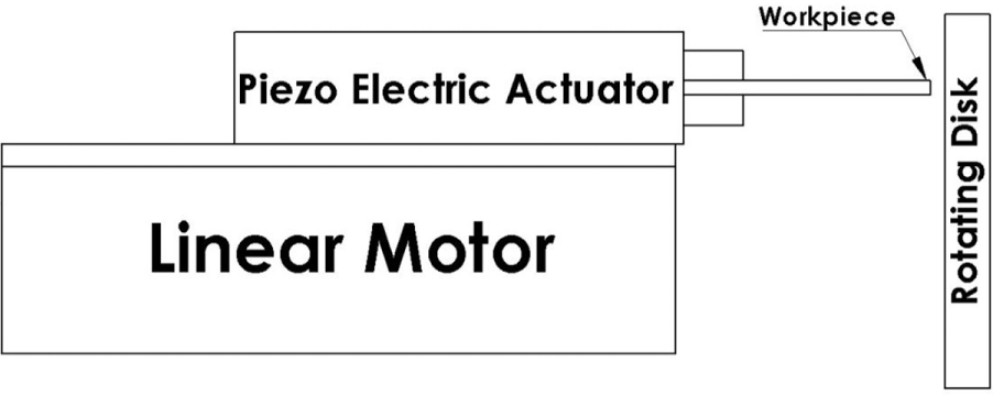
Dual-stage feeding mechanism.
The main goal of this structure was to maintain a stable machining process by controlling the gap width at desired level. The linear motor fed the piezo actuator to guarantee the PZT has a buffer distance from the electrode which was in the range from 25 to 100 µm. The buffer range ensured that at any machining status, the piezo actuator has a minimum distance of 25 µm to respond to any short-circuit spark, and the PZT has enough backward and forward range to move the workpiece and respond to the changes in the spark gap. Once the PZT reached its forward limit (100 µm), it was required to return to the minimum limit (25 µm) and start another cycle. At the same time, when the PZT was returning to the “25 µm” position, the linear motor would compensate the difference in workpiece position by 75 µm to ensure that the workpiece is always at a distance 20 µm away from the tool, as shown in Figure 2.
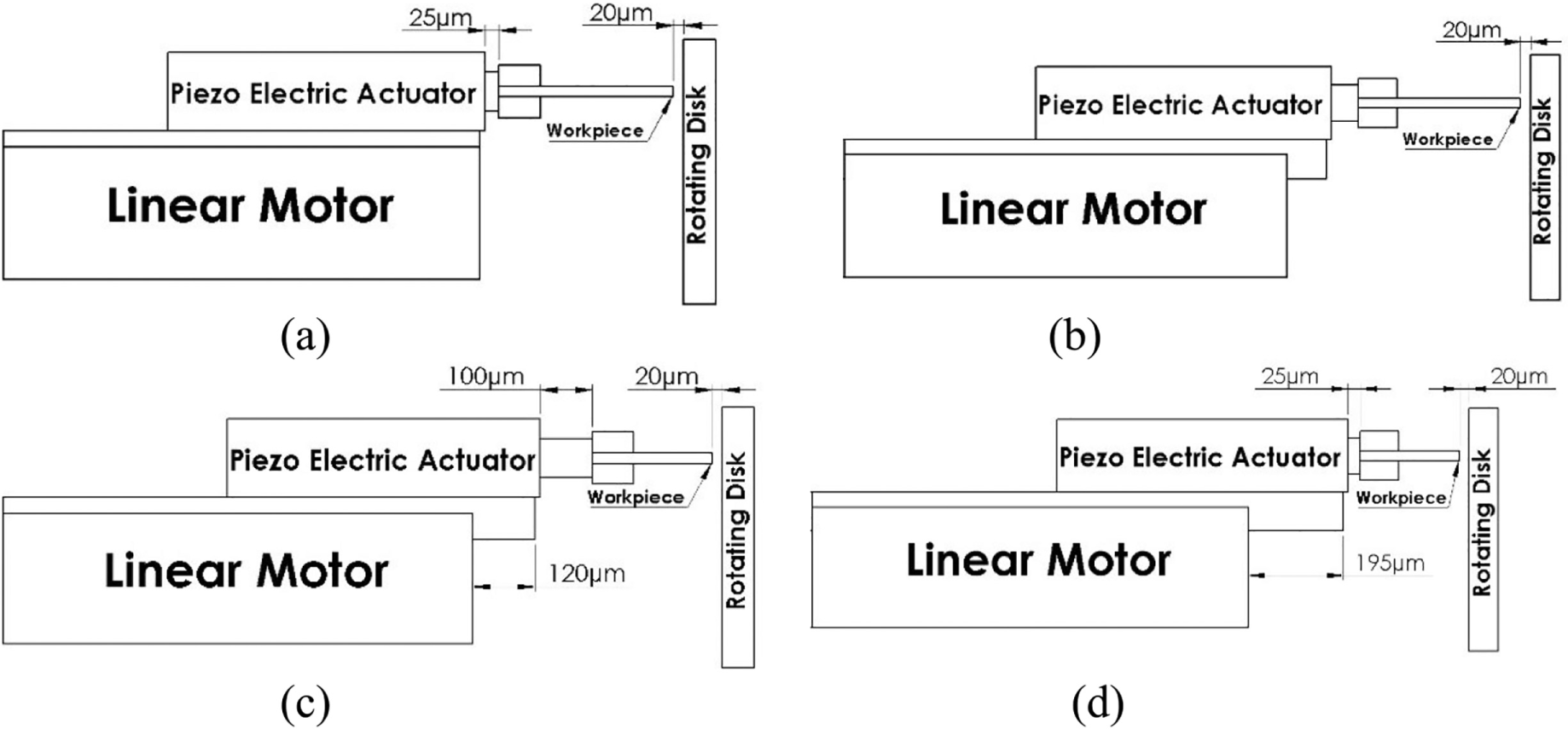
Schematic drawing for the feeding process of the dual-stage feeding mechanism: (a) initial position where the PZT is at 25-µm position and the gap is 20 µm from the rotating disk, (b) the machining started by moving both actuators PZT and linear motor maintaining a gap of 20 µm, (c) the PZT reached the full-range position, (d) the PZT moved backward to the 25-µm position, and the linear motor moved forward to compensate the 75 µm and the machining started again.
To reduce the delay time caused by the separate movements of the linear motor which compensates the difference in workpiece position (75 mm) which is caused by the volume of workpiece materials being removed and the distance the PZT traveled when it moved back to the 20-μm position, the speed of the linear motor should be changed based on the speed of the PZT. While the speed of linear motor depends on the PZT speed and its position, the classical control theories cannot control the feeding process, which requires an intelligent control system to perform this task.
Design of the fuzzy controller
Since EDM is a complicated, stochastic, nonlinear, and time-variant process, it is very difficult to obtain a mathematical model of the process. Therefore, a fuzzy control system will be used to control the linear motor speed. The fuzzy system is composed of three parts: fuzzification, inference mechanism, and defuzzification, as shown in Figure 3. The fuzzification converts the input values to linguistic variables which become the input for the inference system, while the defuzzification converts back the output of the inference system (linguistic output) to crisp values. The inference system is the brain of the fuzzy system. It uses linguistic if-condition (rule-base) statement to calculate the output values based on the input values. Using LabVIEW software, the fuzzy system was built with two inputs and one output. The following section shows the inputs, output, and rule-base for the fuzzy system.
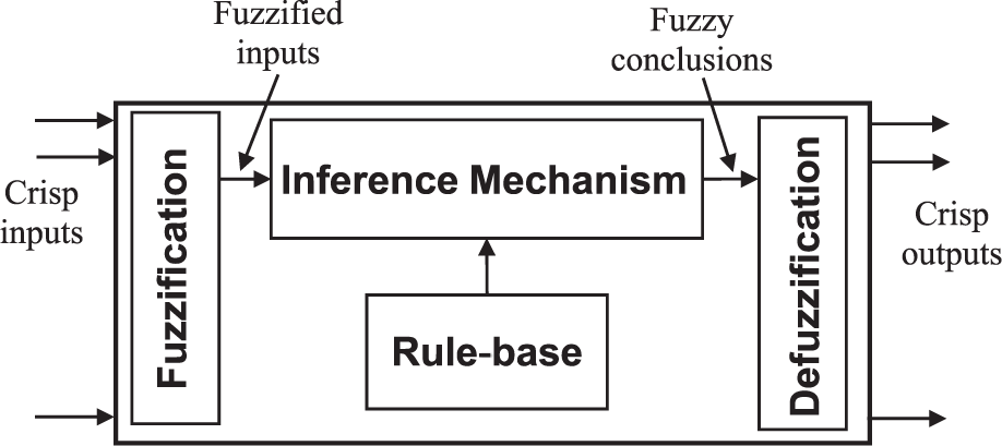
Fuzzy system components.
Fuzzy control input and output variables
This intelligent system (fuzzy) will be used to control the speed of the linear motor using two inputs, PZT position and the change of the PZT position, and one output, the linear motor speed.
Current position of the PZT
PZT changes its position with high frequency rate; the current PZT position is an important input to the fuzzy control to keep an acceptable buffer range for the feeding mechanism. The maximum range of the PZT is 100 µm, so the range of the first fuzzy input PZT position is (0, 100), and it is divided into five fuzzy subsets: very low, low, medium, high, and very high. These subsets are membership functions; as shown in Figure 4, Gaussian shape was chosen for the membership functions.
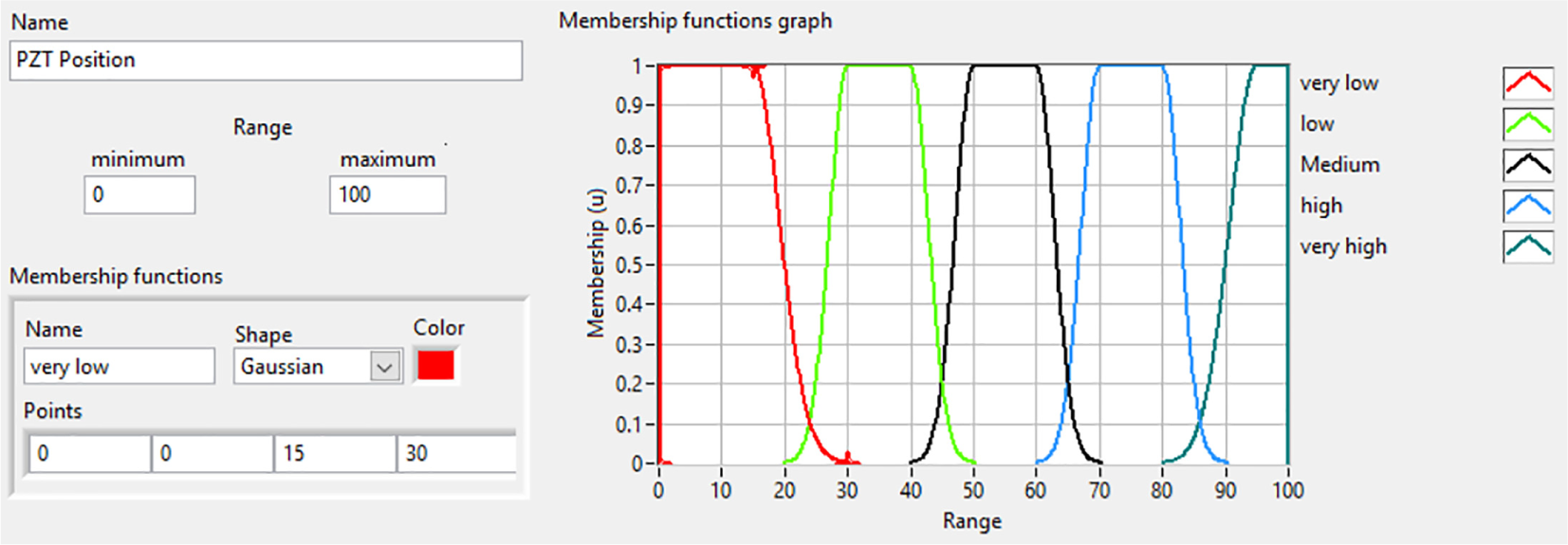
Fuzzy input (PZT position) membership functions.
Change in the average position of the PZT
While the running time of every control cycle is approximately equal, the change in the average PZT position will be used instead of the change rate of the average PZT position. Based on the PZT position range (0–100) and the human experience, the maximum change of the PZT average will be chosen as 50 µm; as the PZT moves backward and forward, the range of the average PZT position is (–50, 50). In addition, this input is divided into five subsets as well: negative large (NegLrg), negative small (NegSml), zero, positive small (PosSml), and positive large (PosLrg). The membership functions for this input is shown in Figure 5, which illustrates the distribution of the membership functions over the range.
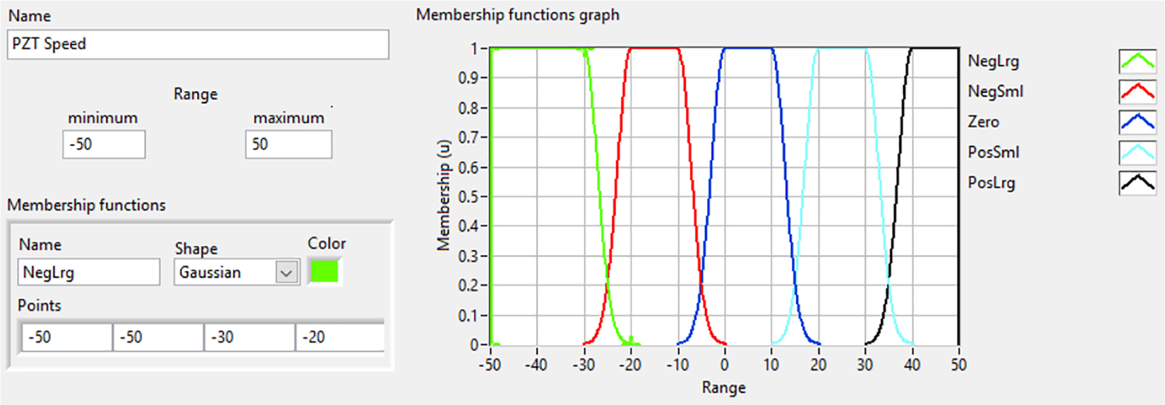
Fuzzy input (change in average PZT position) membership functions.
Speed of the linear motor
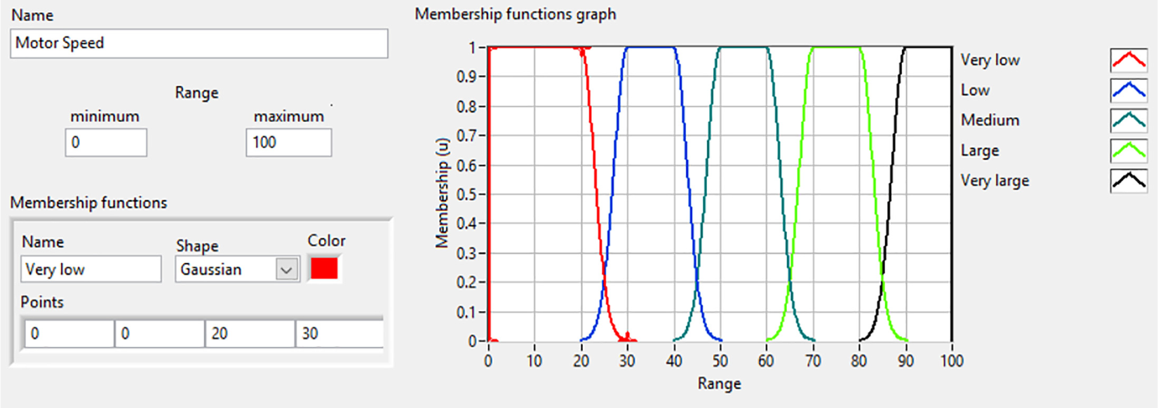
Since the main aim of using the linear motor is to feed the PZT and compensate the distance caused by the removed material during the machining process, the speed of the linear motor should relate to the MRR, which in turn is dependent on the change rate of the PZT position. The range of the linear motor speed is chosen to be from 0 (stationary motor) to 100 (maximum speed). This range is divided into five fuzzy subsets: very low, low, medium, large, and very large. Figure 6 shows the membership functions for the speed of linear motor.
Fuzzy output (motor speed) membership functions.
The rule-base
The inference system is the part that is responsible for decision-making in the fuzzy system. This part requires some if-then conditions to be used in taking that decision. The if-then conditions are built using the linguistic input and output variables. The human experience will be the logic to build this rule-base. In our controller system, the speed of the linear motor will be calculated based on the PZT position and its speed. If the PZT position is very low in the range of 20 µm and the PZT speed is low, it indicates that the linear motor speed is enough to feed PZT and compensate the removed material. Therefore, it is not needed to change the linear motor speed, and the fuzzy output should be low. This can be written in if-then statement as, IF “PZT position” is “Low” and “PZT speed” is “Low,” then “Motor speed” is “Low.”
Whereas, when PZT position is in the range of 50–60 µm (medium) and the PZT speed is in the range of 40–50 (positive large), the MRR will be higher than the linear speed, and if the linear speed is not increased, the forward PZT buffer will be decreased, and the PZT will reach its full working range and start a new cycle. Therefore, the linear motor speed needs to be increased in higher level, this can be written in if-then statement as, IF “PZT position” is “Medium” and “PZT speed” is “PosLrg,” then “Motor speed” is “Very large.”
The following Table 1 contains the rule-base of our fuzzy controller.
Rule-base of the fuzzy controller.
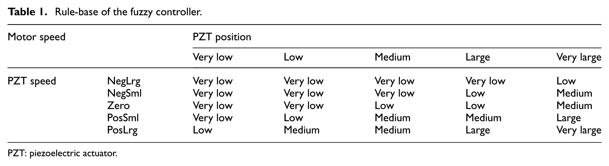
PZT: piezoelectric actuator.
Experimental setup
The EDG experiment system consists of five sub-systems: a power source system, a rotating wheel electrode, the fluid system, the dual-stage feeding mechanism, and control system, as shown in Figure 7. The main power supply is a transistor-type power supply with Voc of 90 V and the maximum current of 10 A. The fluid system contains a dielectric tank which would be filled up with the dielectric before the machining starts; this fluid is flushed from a storage space to the tank by a pump. The rotating wheel electrode disk is mounted on a hydraulic motor.
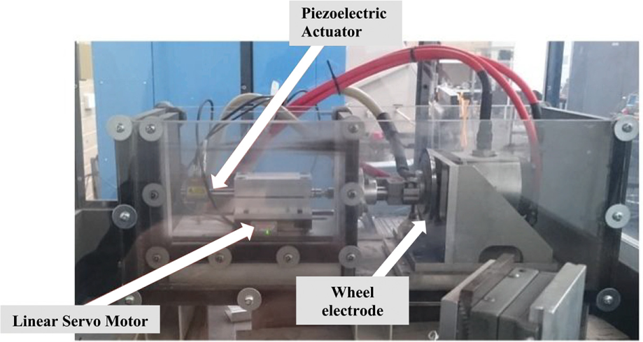
Photos of specially built EDG machine.
The dual-stage feeding mechanism consists of a linear motor and a PZT on the top of the linear motor; the workpiece is mounted on the tip of the feeding mechanism. The main controller was built using LabVIEW software. The linear motor was controlled through AKD factory-built power controller; the position feedback signal was read by a linear encoder through an analog circuit. In addition, the PZT was controlled through THORLAB controller which provided the actuator with the required power and read the position using strain gauges; this controller was connected to the main controller device using an USB port.
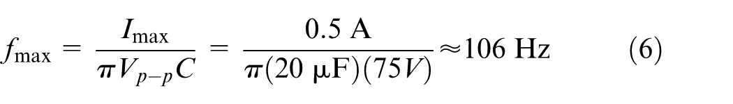
Frequency is an essential parameter to determine the effectiveness of using the PZT in high-speed applications. The bandwidth of a piezo controller can be estimated based on the following parameters:
The maximum current
The load capacitance
The desired signal amplitude
The absolute maximum bandwidth of the driver, which is independent of the load being driven.
The band width of the PZT is calculated as follows:
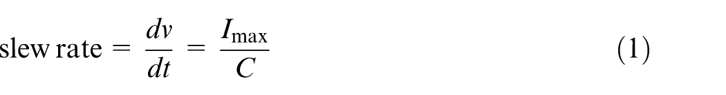
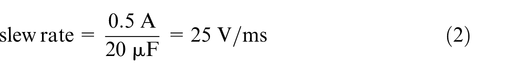
Slew rate, the change in charge with respect to time
The bandwidth of the system usually refers to the system’s response to a sinusoidal signal

where
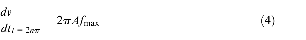
Using equation (1), the maximum frequency
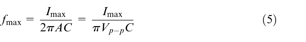
where the peak-to-peak voltage
Substituting the values of
Control and performance test of EDG
The spark gap is critical in controlling the EDM process; therefore, it is important to control the feeding mechanism to keep the gap at the desired value. The proposed control algorithm was based on the simultaneous movement of the linear motor and the PZT to respond to the changes in spark status. As shown in Figure 8, the control process started by putting both actuators (PZT and linear motor) at the zero position, then the linear motor moved to the position of 45 µm from the workpiece, while the PZT moved to the position of 25 µm (this gave the PZT a backward buffer of 25 µm to use if short-circuit or aching status occurs). This makes a gap between the workpiece and the tool of about 20 µm. During the machining process, the PZT responded to the changes in gap distance which was caused by the volume of removed material from the workpiece and the changes in debris concentration in the gap. Since PZT moved forward and backward, the position of PZT increased from 25 to 100 µm eventually. While in the machining process, the PZT moved backward and forward based on the spark status, so the average PZT position was calculated and used as an effect factor to change the linear motor speed. During this movement, the linear motor moved slowly to compensate the enlarged distance caused by removed material. The speed of the linear motor was changed based on the change in average position of the PZT. The average position of the PZT was calculated for each selected range and entered to the controller; the controller output was added to the speed of the linear motor. The speed of the linear motor reflected the machining speed (which was related to the rate of the PZT position changes) and kept the PZT buffer of 25 µm and more. The position of PZT was always more than 25 µm and less than 100 µm, which gave the PZT enough range to move backward with high speed in responding to the short-circuit status. In the case of arc spark, the PZT moved backward by about 10 µm to increase the spark gap allowing the current to decrease and the discharge back to normal status.
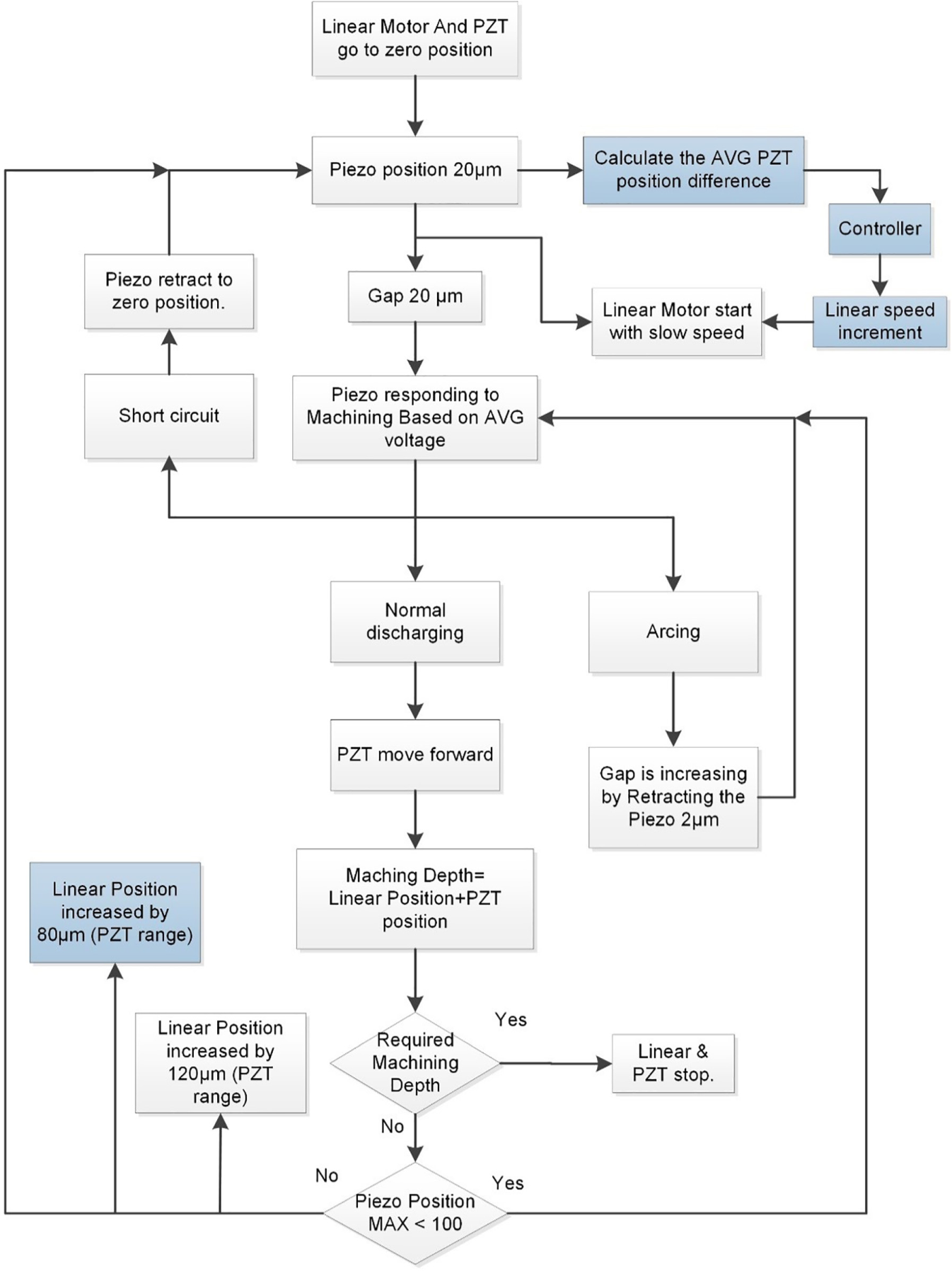
Block diagram of the proposed control of dual-stage feeding mechanism (included the blue blocks) and the conventional method.
In order to test the performance of the new algorithm, experiments were conducted, and machining results achieved using the current algorithms 13 were compared with the results of our algorithm with the same machining parameters. The current control algorithm is based on moving each actuator individually. The PZT responded to the changes in the spark status; once the PZT reached its limit, it stopped and returned to its zero-position waiting for the other actuator, linear motor, to move and compensate the distance of materials removed by the PZT (Figure 8).
In the new algorithm, two control systems were used to control the speed of the linear motor: constant speed of linear motor and fuzzy-controlled speed. Since the optimal speed of the linear motor is not known, experiments were performed to determine the maximum speed of the linear motor which can still maintain stable machining. While the fuzzy controller has two input, PZT position and PZT speed, the fuzzy output was changed based on these inputs, as shown in Figure 9.
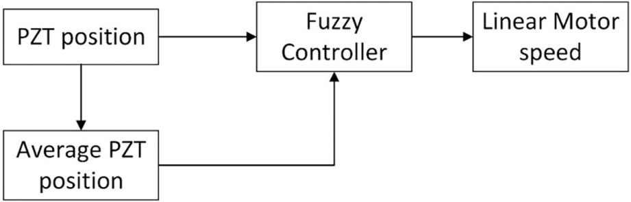
Fuzzy controller diagram.
Results and discussions
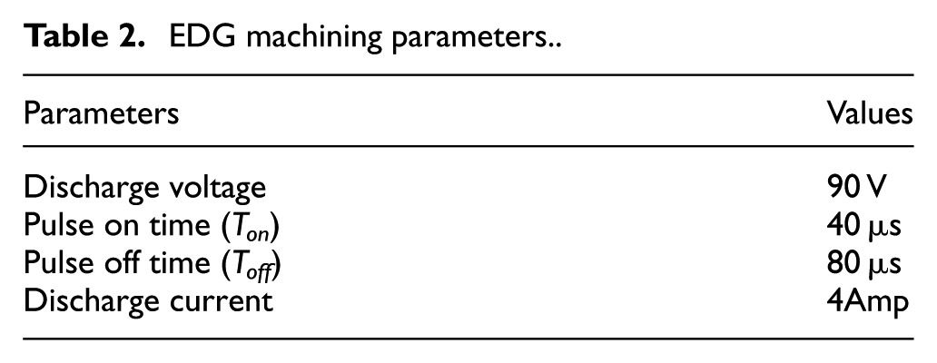
The workpiece used in the experiments are strips made of brass copper. The cross-section of the workpiece is 3 mm × 1 mm and the length is 50 mm (Figure 10). The tool electrode is a copper tungsten wheel which was driven by a hydraulic motor rotating at a fixed rotating speed of 250 r/min (Figure 11). The diameter of the wheel electrode is 110 mm, and the thickness of the wheel is 7 mm. The machining parameters used in the experiment are shown in Table 2.
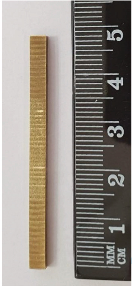
Machined copper strip used in the experiment.
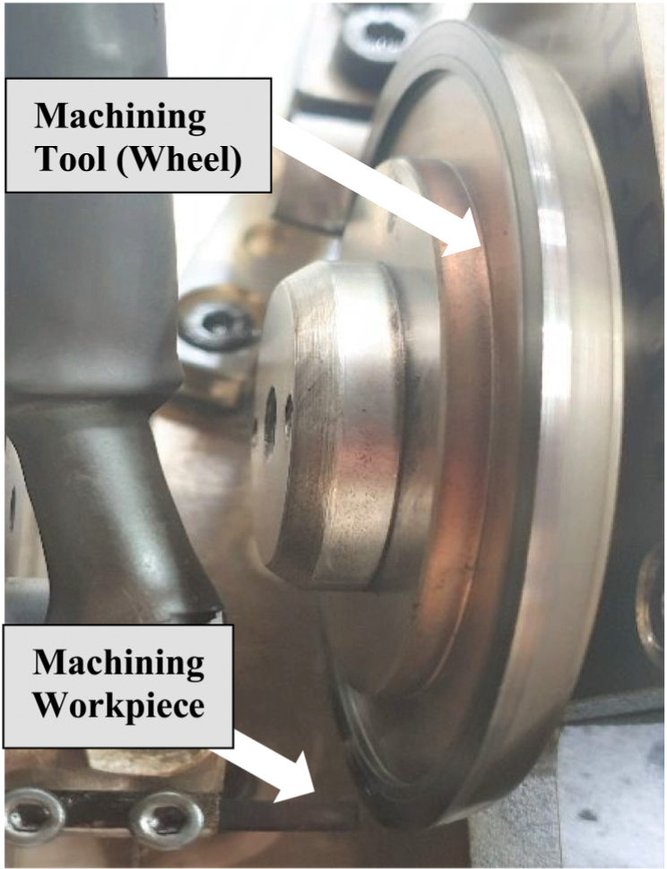
Copper tungsten wheel electrode.
EDG machining parameters.
Both algorithms were built using LabVIEW software with the average gap voltage being the feedback variable for the machining process. The position of both actuators was measured during the discharging process, and the machining time was recorded as well to investigate the performance of both algorithms which were characterized by MRR. The MRR was calculated by dividing the machined length by the time required to machine that length. The machining time and actuators position were recorded and measured from when the first spark occurred while the machined length was calculated by adding the difference between the initial and the final positions of both actuators.
Figure 12 shows the position of the actuators based on the conventional algorithm. The solid horizontal line segments in black color represent the position of the linear motor during the machining process, whereas the blue curves represent the PZT position. The linear motor was waiting for the PZT to reach the maximum limit in order to move forward. This process required the PZT to stop while the linear motor is moving, which was repeated 10 times while the removed length of workpiece was 1300 µm and it consumed 660 s.
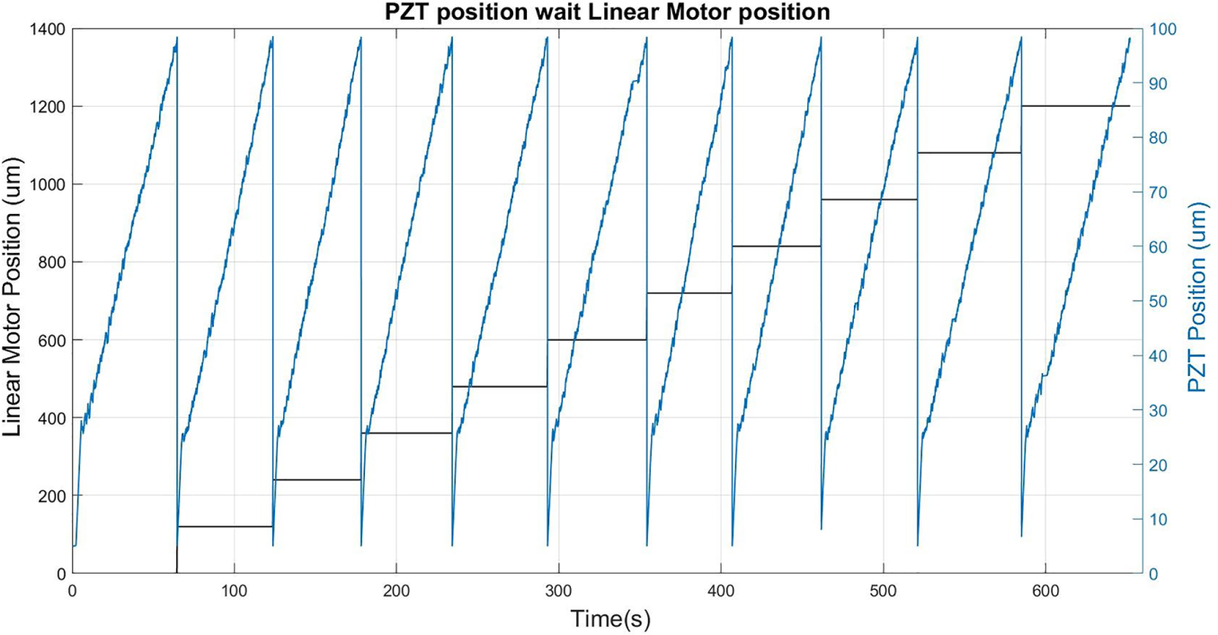
PZT and linear motor position while feeding 1300 µm (existing algorithm).
The results of the proposed new algorithm are shown in Figure 13. According to the new algorithm, the linear motor was moving forward with a constant speed, while the PZT was responding to spark status. When the PZT reached its maximum range, the PZT would move backward to zero and the linear position increased by a distance equal to the PZT range (100 µm). In the entire machining distance of 1300 µm, the PZT reached its maximum range four times, and the overall machining time was 440 s.
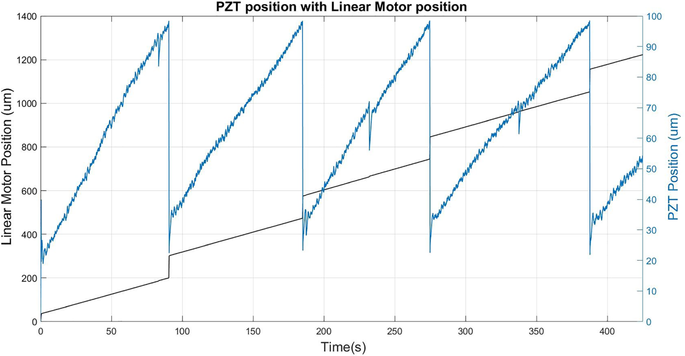
PZT and linear motor position while feeding 1300 µm (the proposed algorithm with constant linear speed).
Fuzzy control was used in the third experiment to control the speed of the linear motor. Using our proposed algorithm by moving both actuators together, it required 410 s to machine the same specimen length (1300 µm). As shown in Figure 14, the fuzzy controller was changing the linear motor speed continuously based on the PZT position and PZT speed, which kept the PZT in working range of 40–60 µm and prevented the PZT from reaching its maximum range.
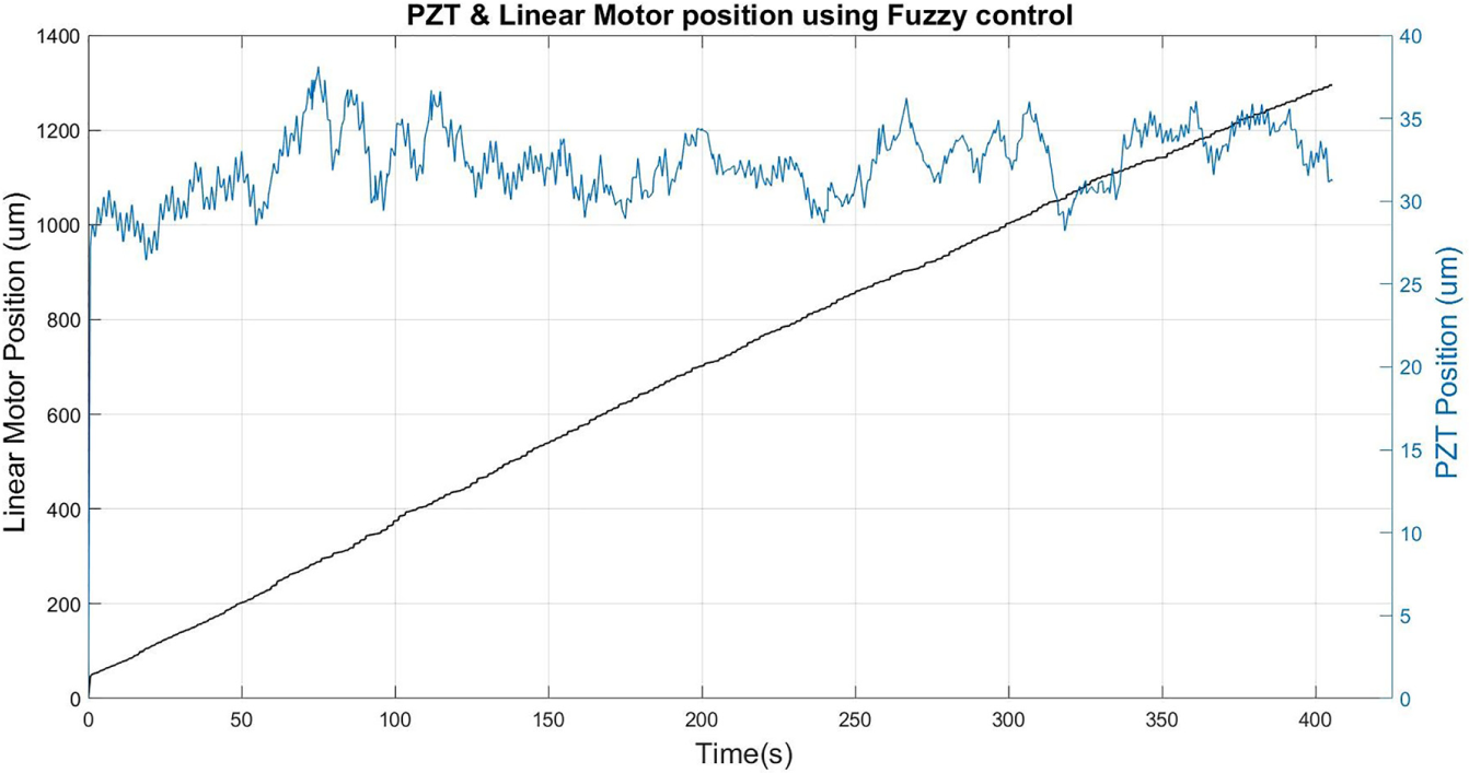
PZT and linear motor position while feeding 1300 µm (proposed algorithm with fuzzy control).
The MRR achieved using the fuzzy controlled new algorithm was 3.17 µm/s and was 2.95 µm/s when using the new algorithm, but the speed of the linear motor was kept constant; however, the MRR achieved using the conventional algorithm was 1.96 µm/s, as shown in Figure 15. This difference in MRR was due to the excess time caused by the stop of the PZT waiting for the linear to move. There was no discharging during this waiting period. Therefore, the more times the PZT stopped, the more efficient the new algorithm would be, which was achieved by the fuzzy controller with continuous machining without any stop of the PZT.
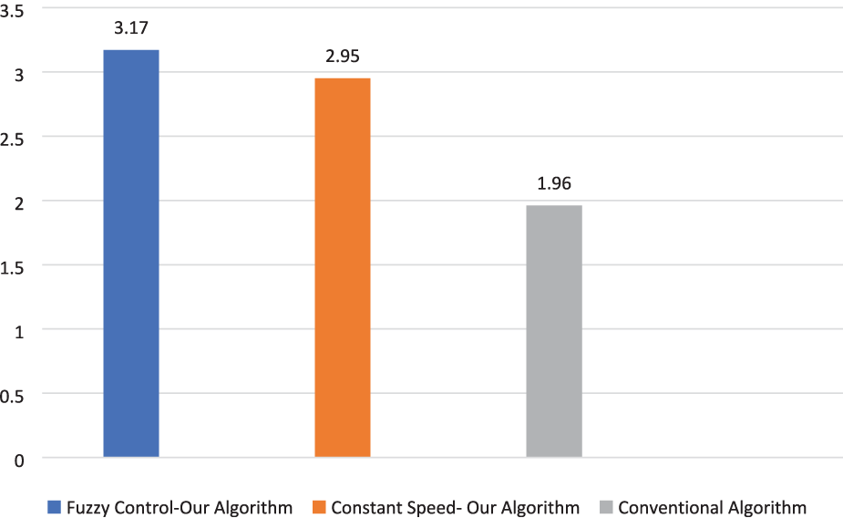
Material removal rate for the three control systems.
Conclusion
A new control algorithm was developed in this article to drive the linear motor and PZT in a dual-stage feeding mechanism for achieving high machining efficiency in EDM processes. Two control strategies were used to control the speed of the linear motor in the new algorithm: constant speed and fuzzy-controlled speed. Three machining processes were conducted (1300 µm each) using the conventional algorithm, the new algorithm with constant linear speed, and the new algorithm with fuzzy control linear speed. The MRRs of the three methods were found to be 1.96, 2.95 and 3.17 µm/s, respectively. The new algorithm with the fuzzy control was found 1.6 times faster than the conventional algorithm, and the MRR was more than 1.5 times bigger when compared with the conventional algorithm for machining the same copper strip under the same machining conditions. These outcomes were achieved through eliminating the waiting time of the PZT and ensure the continuity of the machining to obtain the highest efficiency.
According to the experimental results, the speed of the linear motor was found to be a key factor to maintain the stability and speed of the EDM process in using the dual-stage feeding mechanism. Since the feeding speed of the linear motor have to be changed according to the discharging conditions in the machining process, the fuzzy controller was found to be a powerful tool to control the speed of the linear motor performing the fastest stable machining.
Footnotes
Declaration of conflicting interests
The author(s) declared no potential conflicts of interest with respect to the research, authorship, and/or publication of this article.
Funding
The author(s) disclosed receipt of the following financial support for the research, authorship, and/or publication of this article: The research is supported by the Australian Research Council (Discovery Project DP180100762).