
Abstract
In this article, the authors have attempted to use altogether a new hybrid machining process for making the holes in nickel-based superalloy (nimonic alloy) aerospace material and termed it as electro-discharge diamond drilling process. To perform this experimental study, they self-designed and developed a setup which is capable to hold as well as rotate the metal-bonded diamond abrasive tool electrode. They installed this setup on a ZNC 320 sinking electrical discharge machining machine and conducted the experimental study. The effects of input parameters such as gap current, pulse-on time, duty factor and tool rotation on the response parameters such as average surface roughness (Ra ) and average circularity (Ca ) of the drilled hole have been studied. It is observed that electro-discharge diamond drilling process has substantive effects on the improvement of Ra as well as on Ca in comparison to the hole made by stationary electrode electrical discharge machining (die-sinking electrical discharge machining) process. The photographs and micrographs of few selected workpieces were taken by metallurgical microscope and scanning electron microscope, respectively, which commensurate with the findings of the research study.
Introduction
The growth in aerospace technology has resulted in the emergence of the advanced engineering materials such as heat-treated steels, titanium alloys, metal matrix composites, sialon and superalloys. These materials are tailored to possess peculiar characteristics such as high value of hot hardness, fatigue strength, toughness, corrosion resistance, creep and poor thermal diffusivity and so on. However, these induced characteristics in advanced engineering materials do pose challenges to the conventional machining processes in the form of frequent cutting tool failure, production of poor surface quality and inaccuracy in geometrical dimension. The components such as compressor disk and turbine blades of aeroengines are exclusively made of nickel-based superalloy and Ti-alloys, because they are able to retain and maintain their strength and dimensional profile at higher operating temperature for prolong duration of operation even in harsh operating conditions,1,2 and shaping of such components is beyond the usual capabilities of conventional machining. To overcome the above difficulties, the authors have developed and used large number of added techniques in conventional machining too, such as cryogenic machining, laser beam–assisted and plasma heating of workpieces and so on, but found limited success.3,4
To off-set the conventional machining difficulties of these advanced materials, researchers have developed new techniques known as advanced machining processes (AMPs). These AMPs are beam machining processes (BMPs), electrical discharge machining (EDM), electrochemical machining (ECM), jet machining processes (JMPs), ultrasonic machining (USM) and so on. At present, these AMPs have gained considerable acceptance in industries. 5 An EDM is one such AMP, which is being used for making of holes, connecting passages and grooves with intricate shapes/profiles in the components of engines (aeroengines), hydraulics and pneumatics of aircraft, whose designs are very complex and critical. However, due to its lower machining efficiency, EDM is not preferred for general commercial applications.
In EDM, the series of high-frequency discrete electrical sparks produces heat energy between the two opposite polarity electrodes (one is the workpiece and another being the tool) which are duly submerged in dielectric fluid. The produced heat energy of sparks is very high which melts and vaporizes the materials of the workpiece and establishes the plasma channel between the workpiece and tool electrode. During off time of the pulse, the plasma channel and the formed vapor bubbles collapse suddenly which ensure that the molten materials explode into the gap between both electrodes known as inter electrode gap (IEG) and transformed into debris form in dielectric fluid as a result of the effect of sudden cooling. However, due to surface tension and bonding strength between molten material (liquid) and solid section of the workpiece, only partial molten materials explode into IEG. The leftover materials are re-solidified/re-casted on the machined surface of work specimen in the form of overlapped layers resulting in the formations of ridges, protrusions, craters and so on.
To further improve the machining efficiency of the existing EDM, the authors have tried different options such as introducing the rotation in tool electrode and terming it as electrical discharge drilling (EDD) process, use of additives as well as water in dielectric fluid and using the tool electrode made of powder metallurgy and so on. They were successful to some extent, but still the prevalence of lower machining efficiency exists.6–10 At present, the use of hybrid machining processes (HMPs) is being explored to enhance the machining efficiency of conventional as well as nonconventional machining processes. In HMP, two or more than two machining processes are combined to exploit the potential advantage of the constituent processes along with impairing its inherent disadvantages. As per the available literatures, in most of the cases for machining of advanced materials, HMPs are used by either combining metal-bonded abrasive grinding wheel with ECM or EDM. These processes are termed as electrochemical abrasive grinding (ECAG) and electro-discharge abrasive grinding (EDAG), respectively.
The use of metal-bonded diamond abrasive grinding wheels similar to EDAG, known as electro-discharge diamond grinding (EDDG), was first time experimented in erstwhile Union of Soviet Socialist Republics (USSR) for machining of hard conductive materials.11,12 The EDDG has been used in different modes of operation such as surface grinding and cut-off grinding for machining of hard conductive materials and found improved response of material removal rate (MRR) and Ra .13,14 By making use of similar concept, Shu et al. 15 drilled holes in mold steel HPM50 and tungsten carbide P20 materials and found improved value of Ra . They used rotating tool electrode made of fine copper-bonded SiC abrasive in EDM and termed it as electrical discharge abrasive drilling (EDAD).
The holes made by EDM machining in advanced material are inherited with poor surface finish and inaccurate geometry due to the formation of overlapped layers and craters as a result of re-casting of leftover materials on the machined surface. The authors also observed that most of the research articles speak about the improvement of MRR and Ra and very few articles highlight the issues related to Ca of hole made by EDM or EDD process, which are very important parameters. These Ra and Ca are the essential parameters in the cases of specially matched dynamic components such as piston and sleeve/cylinder designed to operate within 2–5 µm clearances. Such components along with rotary as well as axial movement are used for controlling of high-pressure flowing fluid in the various systems of aircraft and aeroengine.
In this study, the authors have attempted to drill the hole in nimonic alloy with the newly conceived and developed concept of electro-discharge diamond drilling (EDDD) process as shown in Figure 1 in which metal-bonded diamond abrasive tool electrode is used. In this process, the rotating metal-bonded diamond abrasive tool electrode removes the materials from work surface by simultaneous influence of diamond grains and continuous discrete electrical sparks, thereby causing the abrasion (micro-cutting) and electro-erosion, respectively. They conducted the experimental study on one parameter at a time (OPAT) approach considering the input parameters such as gap current, tool rpm and duty factor and analyzed its performances for response parameters such as Ra and Ca of the drilled hole with EDDD as well as stationary electrode (die-sinking EDM) process. It is observed that there are substantial and interrelated improvements in the output parameters such as Ra and Ca including the thickness of the formed (thermal infested) layers with EDDD process than stationary electrode EDM process.
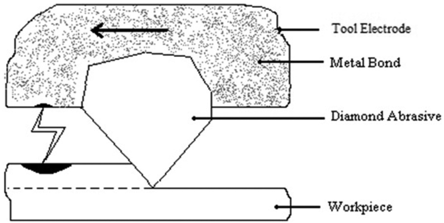
Schematic representation of use of diamond abrasives in rotating tool electrode EDM (EDDD).
EDDD setup and experimentation
EDDD setup
To conduct the experimental study, the authors self-designed and developed a setup, which was capable to hold as well as rotate the tool electrode. The developed setup was assembled on a ZNC 320 EDM machine by replacing its original tool holder as shown in Figure 2. The tool electrode was mounted at the lower side of the rotating spindle assembly which is supported on 04 in number high-speed angular contact bearing of the housing assembly. The spindle is rotated through driven pulley mounted at the upper side of rotating spindle and “V” belt by permanent magnet direct current motor (PMDC) motor (0.187 kW, 1500 r/min). A linear-variable speed controller connected in-line to PMDC motor has been used for controlling the tool rpm. A portable digital tachometer (model: DT 200 1B) supplied by an Electronic Automation Private Ltd (EAPL), India, has been used to measure and calibrate the tool rpm and linear-variable speed controller, respectively.
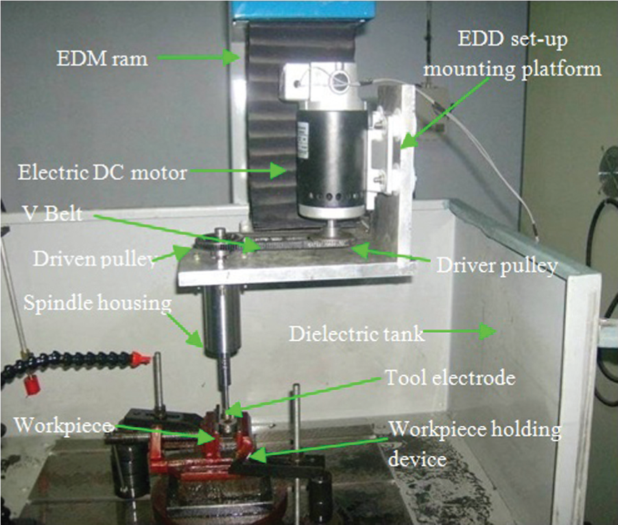
EDDD setup assembled on ZNC EDM machine.
Tool electrode and workpiece materials
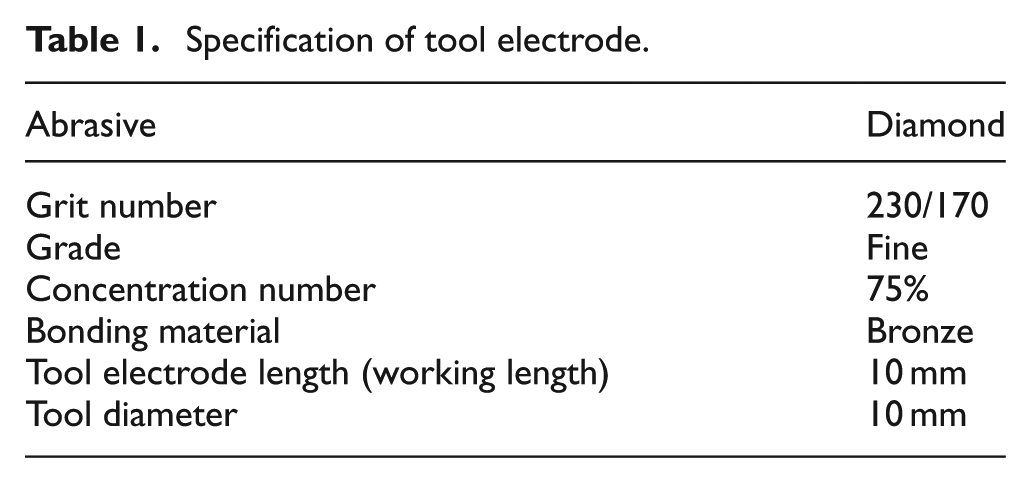
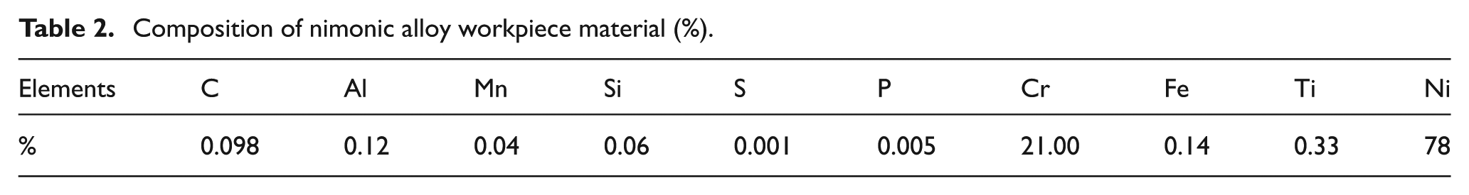
The metal (bronze)-bonded diamond abrasive tool electrode was manufactured with hot iso-statically pressed (HIP) process as per drawing shown in Figure 3. It consists of steel shank at one end and metal-bonded diamond abrasive on the another end as per specification given in Table 1. The total indicating run out (TIR) of the tool electrode was maintained up to10 µm on the EDM machine. The work specimen of 05 mm thickness from 22-mm hot-rolled annealed ground bar of nimonic alloy (Grade AE 435; MIDHANI, India) was prepared (sliced) by wire-cut EDM machine. The chemical composition of the work specimen is shown in Table 2. After measurement of Ca , the entire work specimens were partitioned into two half for facilitating the accurate and precise measurement of Ra .
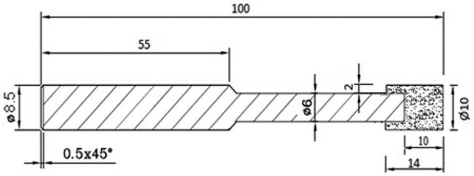
Diagram of metal-bonded EDDD tool (all given dimensions are in millimeter).
Specification of tool electrode.
Composition of nimonic alloy workpiece material (%).
Experimental conditions
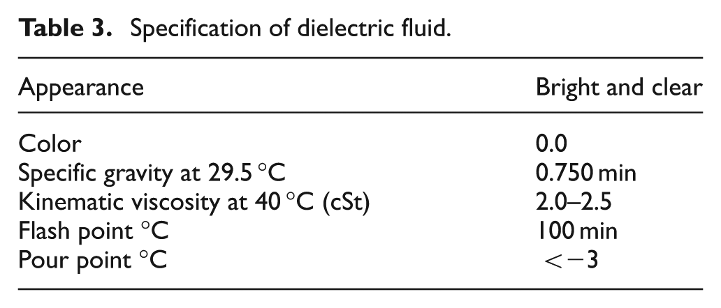
All the experiments were successfully completed with the developed tool electrode in reverse polarity (work connected to negative and tool electrode to positive) of the machine. During EDDD process, a minimum gap is maintained between tool electrode and surface of work specimen, which depends on the local breakdown strength of the dielectric fluid for automatic setting of a particular gap voltage. The original equipment manufacturer (OEM)–supplied dielectric fluid was used during this study, whose specification is shown in Table 3. Work specimen was placed horizontally beneath the tool electrode with the help of spirit level and was clamped tightly on workpiece holding device. For better flushing of eroded debris, an additional supply of dielectric fluid at pressure 0.049 N/m2 and flow rate of 44 cm3/s was made through two pressure hoses in machining zone of the workpieces for better flushing of eroded debris.
Specification of dielectric fluid.
Selection of range of parameters and observations
During pilot experimentation, initially the authors considered all the possible controllable input parameters, but later on decided to use only four main input parameters, that is, tool rpm, gap current, pulse-on time and duty factor and leftover the other parameters such as servo setting, gap voltage and IEG. Because these parameters are automatically controlled by EDM machine (in-built feature of the machine) depending on the type of used dielectric fluid. Also, since there were no much significant effects of change in dielectric pressure and its flow rate on Ra and Ca , these parameters were not taken into consideration too.
During pilot experiments, it was observed that at 175 r/min, the value of Ra was found to be as close to the value obtained at 250 r/min (around 2.0 µm), whereas Ca was found to be around 28–30 µm. However, at increased tool rpm of 800 and with all possible combinations of input parameters, the values of Ra and Ca were both found to be closer to the obtained value at 700 r/min. Based on these observations, the range of input parameters was decided as follows: gap current between 3 and 7 A, duty factor 40%−52% and tool rotation 250–700 r/min along with varying pulse-on time from 20 to 32 µs at fixed pulse-off time of 30 µs.
Measurement of Ra and Ca
A MATRIS model co-ordinate measuring machine (3CMM) with Renishaw (CSP25M) probe having accuracy of 0.0025 mm (2.5 µm) was used to measure the value of Ca by setting the cut-off value at 22.5° with 16 steps on the circumference at a depth of 2.5 mm from the top surface of the hole diameter of work specimen. A Perthometer Type M2 (Mahr) having accuracy of 0.001 µm was used to measure Ra by setting its cut-off value at 0.8 mm with five steps.
Results and discussion
The effects of input process parameters such as gap current, duty factor and tool rotation on Ra and Ca of the hole made by EDDD as well as stationary electrode EDM were studied and analyzed, which are discussed below in brief.
Average surface roughness (Ra)
The desired quality of surface finish is the prime requirement in machining operation, such as holes and connecting channels, in the components of pneumatic, hydraulic and fuel system of aircraft, because pressurized flowing fluid may generate debris from the poorly machined surface which may block the path of flowing fluid/in-line filters as well as introduce inconsistent motion of moving piston in sleeve (cylinder) which are having closer clearances such as 2–7 µm and lead to failure of the system.
Effects of gap current
Figure 4 shows the variation in Ra with gap current for all the considered duty factors and at 250 r/min of tool rotation. At duty factor of 40%, as the gap current increases from 3 to 5 A, Ra increases by 23.42% (from 1.802 to 2.224 µm) and with further increase in gap current to 7 A, Ra increases by 16.95% (from 2.224 to 2.678 µm).This is because with an increase in gap current, the intensity of spark energy increases which subsequently increases the heat energy and discharge power. As a result, large size craters are formed on the machined surface, which is responsible for poor surface finish. Also, similar trend of increasing the surface roughness with increasing gap current is observed at 46% and 52% duty factor; however, the values obtained on these two duty factors are found to be well above the value of 40% duty factor. This is because increase in duty factor with fixed pulse-off time (30 µs) gives sufficient time, so that heat energy could penetrate deeper into work specimen which resulted in the formation of large craters.
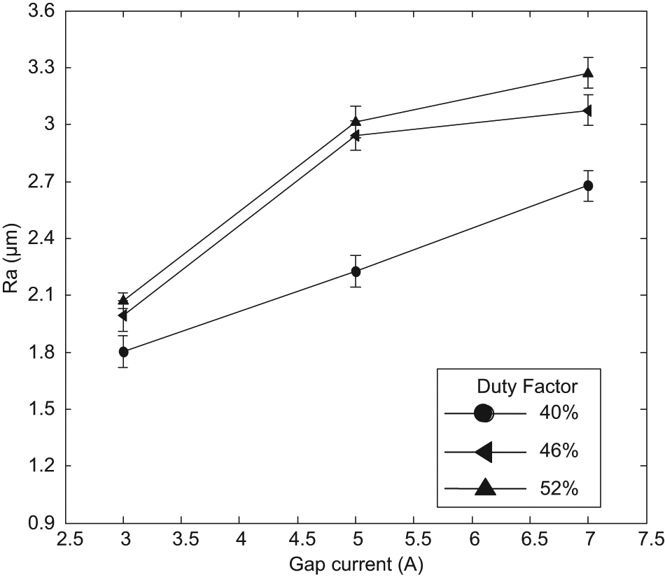
Effect of gap current on Ra for different duty factors.
Effects of duty factor
Figure 5 shows the relationship between the variation in Ra with an increase in duty factor at all the considered tool rpm and at 3 A of gap current. At tool rotation of 250 r/min, Ra increases by 10.54% (from 1.802 to 1.992 µm) with an increase in duty factor from 40% to 52%. This is because increase in duty factor gives sufficient time for heat energy to convect to the work specimen which melts the materials in sufficient quantity but could not be flushed out effectively at low tool rpm from IEG and resulted in an increase in surface roughness. At 400 r/min, with an increase in duty factor from 40% to 46%, Ra increases from 2.351 to 2.389 µm and subsequently improves to 2.253 µm with an increase in duty factor to 52%. This is because of effective melting and removal of eroded debris at increased duty factor and tool rpm, respectively. However, with further increase in tool rpm along with increasing duty factor, improvement in Ra is found to be tremendous. To mention, at 550 r/min Ra improved by 22.34% (from 2.184 to 1.696 µm) and at 700 r/min surface roughness improved by 33.51% (from 2.050 to 1.363 µm). This improvement in Ra is credited to effective removal of re-casted thermal infested layers by the metal-bonded diamond grains (abrasives) of tool electrode coupled with enhanced effective flushing with an increase in tool rpm.
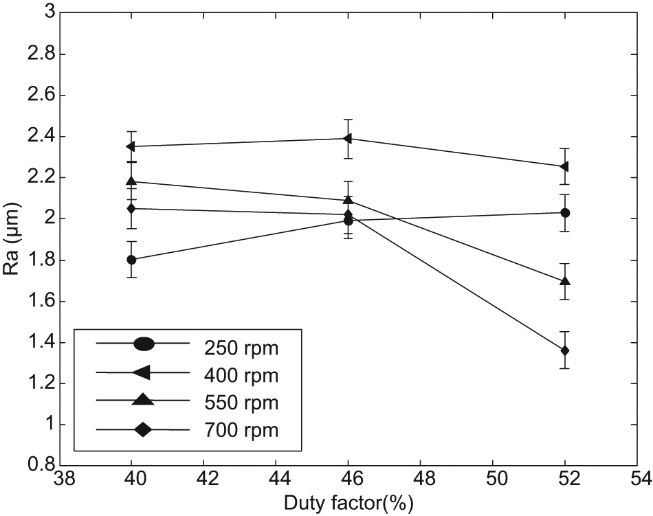
Effect of duty factor on Ra for different tool rpm.
Effects of tool rpm
Figure 6 shows the effect of tool electrode rpm on surface roughness for different gap currents and at 40% duty factor. It is observed that as the tool rpm increases from 250 to 400 r/min, Ra increases initially in increasing order with an increase in gap current. This is because of ineffective flushing of the eroded debris, which results in the formation of re-casted layers in uneven form. However, Ra improves subsequently with an increase in tool rotation to 550 and 700 r/min for all the values of gap current and this is due to the enhancement in effective flushing of eroded debris at increasing tool rpm coupled with effective removal of re-casted (semi-solid) layers by diamond abrasive of tool electrode. Also, it is noted that the values of surface roughness are higher for higher gap current. This is due to the reason that increase in gap current increases the intensity of sparks which produces high heat energy and discharge power. This produces the craters of deeper and larger size as per the increasing order of gap current and subsequently increasing the value of surface roughness.
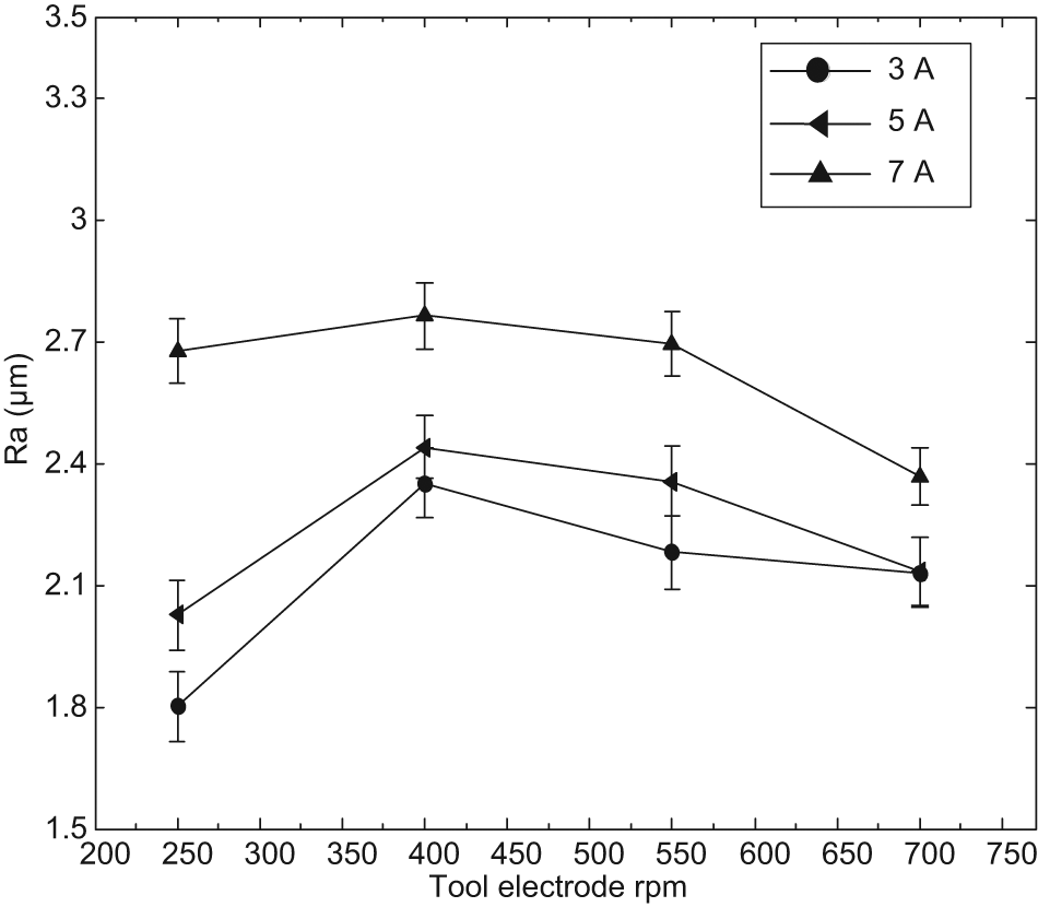
Effect of tool rpm on Ra for different gap currents.
Effects of stationary tool electrode
Figure 7 shows the variation in Ra with gap current for different duty factors and at zero tool rpm. It is observed that Ra increases with an increase in gap current for all duty factors. Ra increases by 14.60% (from 3.15 to 3.61 µm) with an increase in gap current from 3 to 7 A at 40% duty factor and it increases by 8.21% (from 3.41 to 3.69 µm) at 46% duty factor. The increase in gap current along with duty factor is responsible for efficient melting of the materials due to the generation of intensive spark energy and discharge power. But the generated heat energy is not able to dissipate uniformly to workpiece due to poor thermal diffusive characteristics which result in uneven melting of the materials and formation of deep craters on the machined surface. This is clearly observed at 52% duty factor where the value of Ra has been increased between 3.80 and 4.38 µm with the same value of increasing gap current. Tool electrode being stationary has also lead to an increase in Ra value and that is because of ineffective flushing of eroded debris at high value of gap current as well as duty factor.
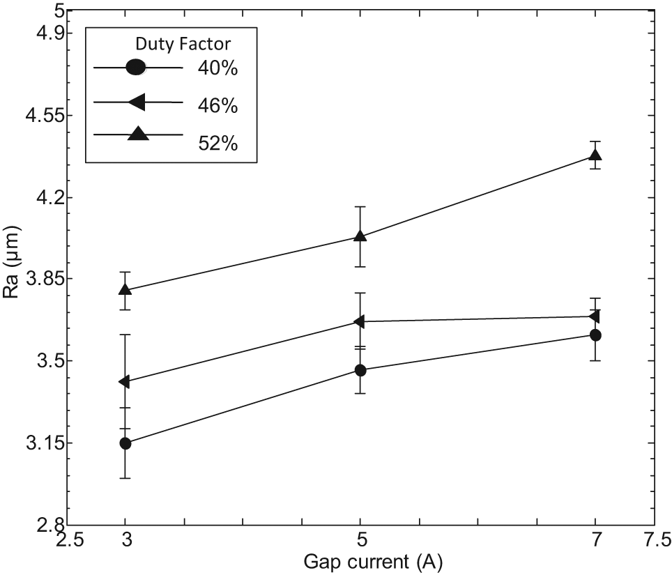
Effect of gap current on Ra for stationary electrode EDM.
Average hole circularity (Ca)
The effects of varying input parameters of EDDD as well as stationary electrode EDM on average circularity are analyzed and explained in brief as given below.
Effects of gap current
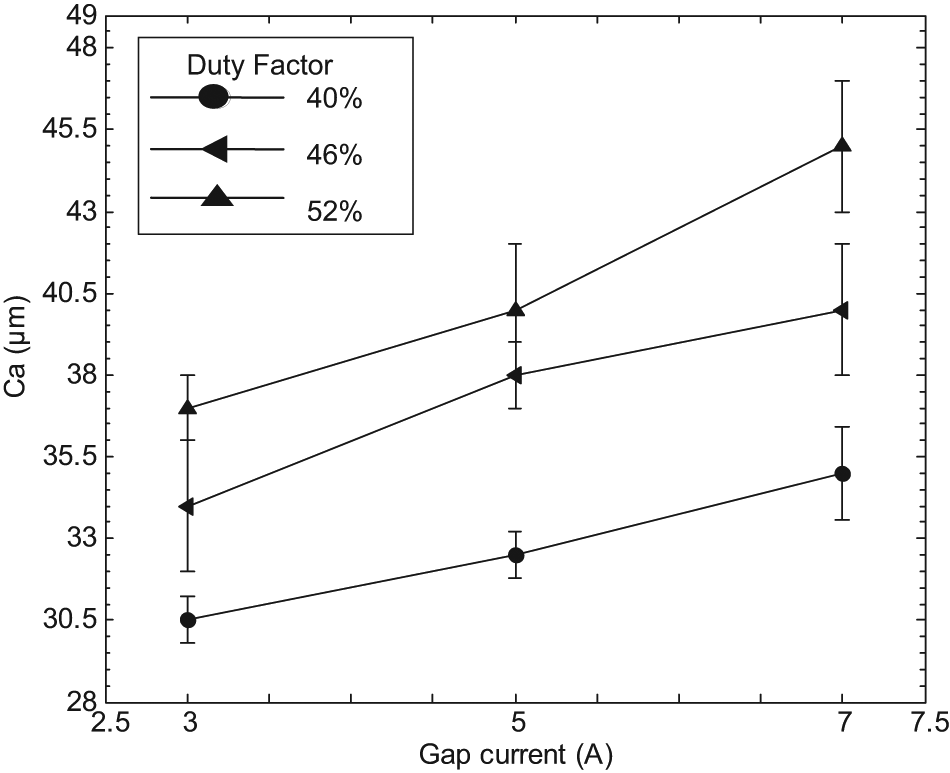
Figure 8 shows that Ca increases with an increase in gap current on all duty factors and at 700 r/min of the tool rotation. It is observed that at 40% of duty factor, Ca increases by 17.39% (from 23 to 27 µm) with an increase in gap current from 3 to 7 A. This is because of the formation of deep and enlarged craters on the machined surface as a result of increased gap current. At 46% duty factor, it initially increases from 28 to 29 µm with an increase in gap current from 3 to 5 A, and with further increase in gap current to 7 A, Ca improves by 1 µm (from 29 to 28 µm). Also, the Ca values at 46% duty factor are found to be much above than that of 40%. The increase in gap current at 46% duty factor ensures that the moderate heat energy with discharge power is available for longer duration which should have melted and vaporized the materials effectively. But due to poor thermal conductivity and higher precipitation temperature characteristics of work specimen, melting of the materials was partial. This resulted in re-solidification of partial molten materials in uneven form which increased the value of Ca . However, with a further increase in duty factor to 52% along with an increase in gap current, the Ca improves and reached to almost close value of 40% duty factor. This is because of effective melting due to higher pulse-on time, which resulted in conduction of generated heat energy effectively to work specimen and effective removal of re-casted layers by diamond abrasive.

Effect of gap current on Ca for different duty factors.
Effects of duty factor
Figure 9 shows the effect of increase in duty factor on Ca for all tool rpm and at 3 A gap current. It is observed that at 40% of duty factor, with an increase in tool rotation from 250 to 400 r/min, Ca increases by 7.41% (from 27 to 29 µm). This is because low-duty factor gives less time to conduct the heat energy to work specimen which results in poor melting, and ineffective removal of eroded debris coupled at low rpm increases the value of Ca . However, Ca improves to 26 and 23 µm with an increase in tool rotation to 550 and 700 r/min, respectively, and this is due to enhanced flushing of eroded debris of molten materials accompanied with high fluid (dielectric) flowing energy. As the duty factor increases to 46%, moderate melting of materials occurs due to moderate time available for heat energy to convect to work specimen, and effective removal of eroded materials with increasing tool rotation from 250 to 400 r/min improves the Ca accordingly. However, with a further increase in tool rotation to 550 and 700 r/min, the formed heat energy globules of spark energy get spattered which result in poor and nonuniform convection of heat energy to work specimen. This results into nonuniform melting of materials of the work specimen and duly coupled with effective flushing of eroded debris at increasing rpm has increased the unevenness of the machined surface, in turn increases the value of Ca . However, on further increase in duty factor to 52%, Ca improves very drastically at increasing tool rpm. This is because of enhanced melting of materials due to sufficiently increased pulse-on time and removal thereafter due to enhanced effective flushing of eroded debris duly accompanied with removal of re-casted thermally infested layers by diamond abrasive of tool electrode. To mention, Ca improves by 14.29% with an increase in duty factor from 46% to 52% at 700 r/min.
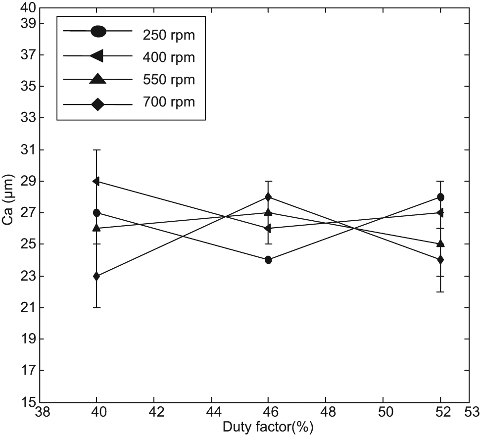
Effect of duty factor on Ca for different tool electrode rpm.
Effects of tool rpm
Figure 10 shows that there is a quite appreciable improvement in Ca with an increase in tool rpm for all gap currents and at 40% duty factor. It is observed that at 3 A of gap current, Ca improves by 18.52% (from 27 to 22 µm) with an increase in tool rotation from 250 to 700 r/min. At 5 A of gap current, Ca improves by 27.27% (from 33 to 24 µm) with an increase in tool rotation from 250 to 700 r/min. Similarly, improvement in Ca is observed by 15.63% (from 32 to 27 µm) with an increase in tool rotation at 7 A gap current. The improvement in Ca is credited to the combined effect of effective flushing as well as removal of re-casted thermal infested layers by bonded diamond grains of tool electrode. Also, the obtained values of Ca at 7 A are found below the values obtained at 5 A. This is because at 7 A of gap current, the produced spark has high heat energy with discharge power which uniformly and effectively melted the materials in spite of low thermal conductivity of work specimen and ensured the uniform removal of the materials of the machined surfaces which in turn improved the value of Ca .
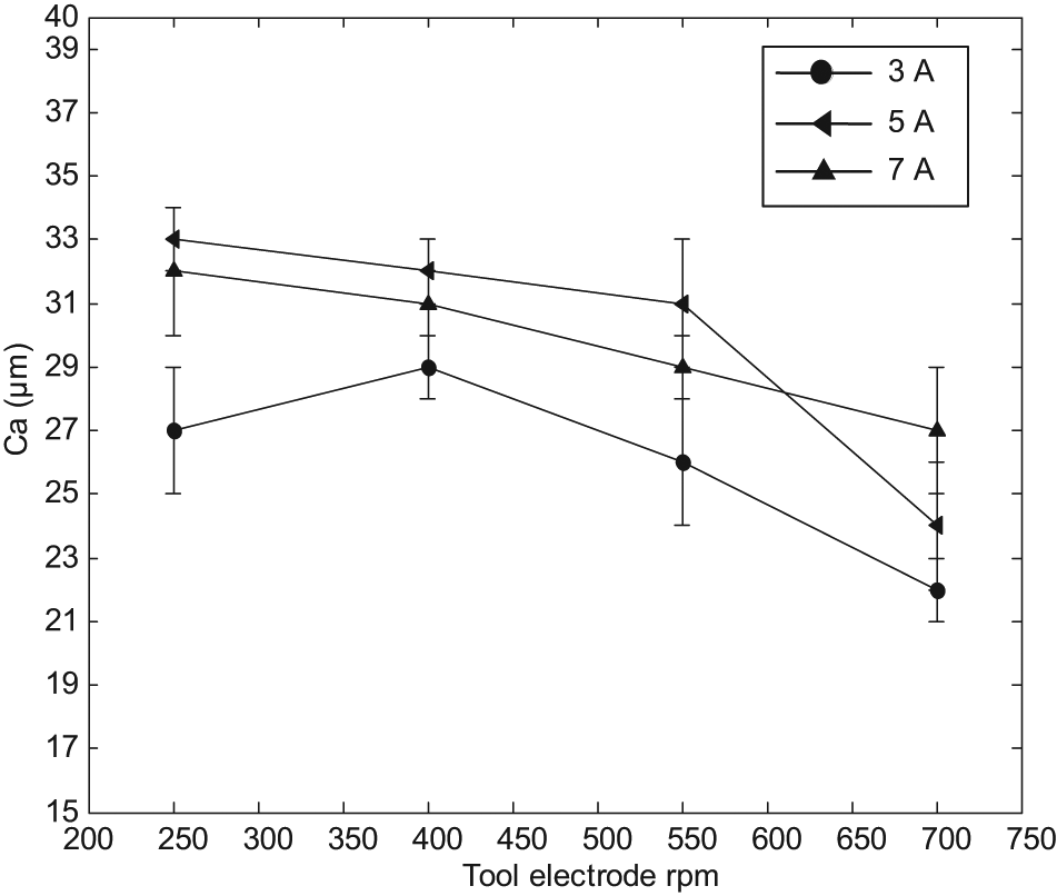
Effect of tool electrode rpm on Ca for different gap currents.
Effects of stationary tool electrode
Figure 11 shows the relation between Ca and gap current for different duty factors at zero tool rpm. It is observed that the Ca increases with an increase in gap current on all the considered duty factors. At 40% duty factors, Ca increases by 16.13% (from 31 to 36 µm) and at 46% duty factors, it increases by 17.67% (from 34 to 40 µm). This is due to the formation of craters at increased gap current and re-solidification of leftover materials due to ineffective flushing of dielectric due to stationary electrode. The effect of ineffective flushing due to stationary electrode is clearly observed at 52% duty factor where the Ra has increased by 21.62% (from 37 to 45 µm) and that too very sharply between 5 and 7 A of gap current.
Effect of gap current on Ca for stationary electrode EDM.
Scanning electron microscope observation of machined surface
Micrographs and photographs of the three selected machined workpieces have been taken using scanning electron microscope (SEM) and metallurgical microscope which are shown in Figures 12 and 13, respectively. This has been done especially to appreciate and differentiate the effect of rotation of the tool electrode against the stationary electrode of EDDD process. It is observed that at lower value of input parameters especially with zero tool rpm, the irregular bubble-like structure is seemed to be formed as shown in Figure 12(a), whereas with same input parameter and at 250 rpm, the formed bubbles seem to be collapsing leaving behind the linear shadows of deep black color (hairline), as shown in Figure 12(b). This is because of increased flushing of eroded debris from IEG. As the tool rotation increased to 700 rpm along with gap current and pulse-on time (duty factor), the formed bubbles collapsed as shown in Figure 12(c). This is because of the impact of the rotation of diamond abrasives of tool electrode coupled with enhanced melting as well as effective flushing of eroded debris from IEG. The deposition of re-casted (thermal infested) layer is very clear as shown in Figure 13(a), whereas it has been progressively decreasing as shown in Figure 13(b) and (c), respectively (clearly observed by enlarging the images), with increase in tool rpm due to the effect of spattering of the formed bubbles and credited to the improved flushing at increased tool rpm.
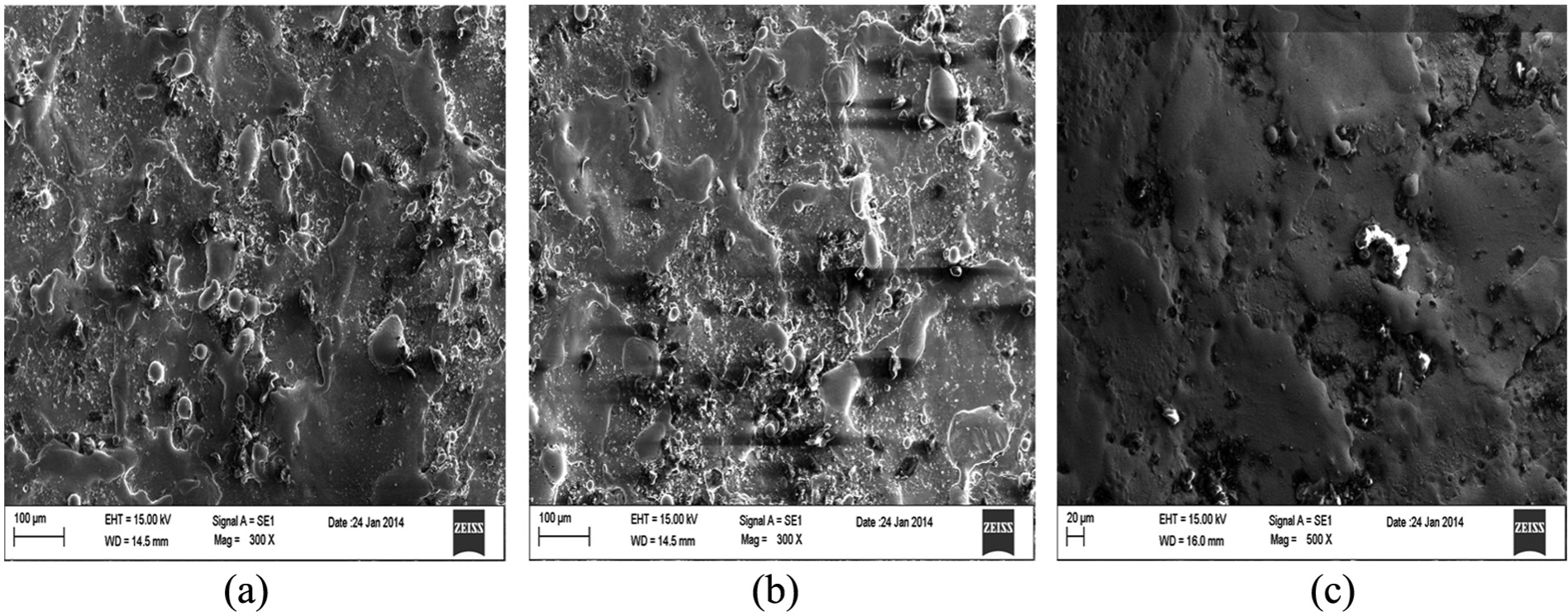
Micrographs of machined surface using SEM: (a) I = 3 A, duty factor = 40% and tool rpm = 0.00; (b) I = 3 A, duty factor = 40% and tool rpm = 250 and (c) I = 7 A, duty factor = 52% and tool rpm = 700.
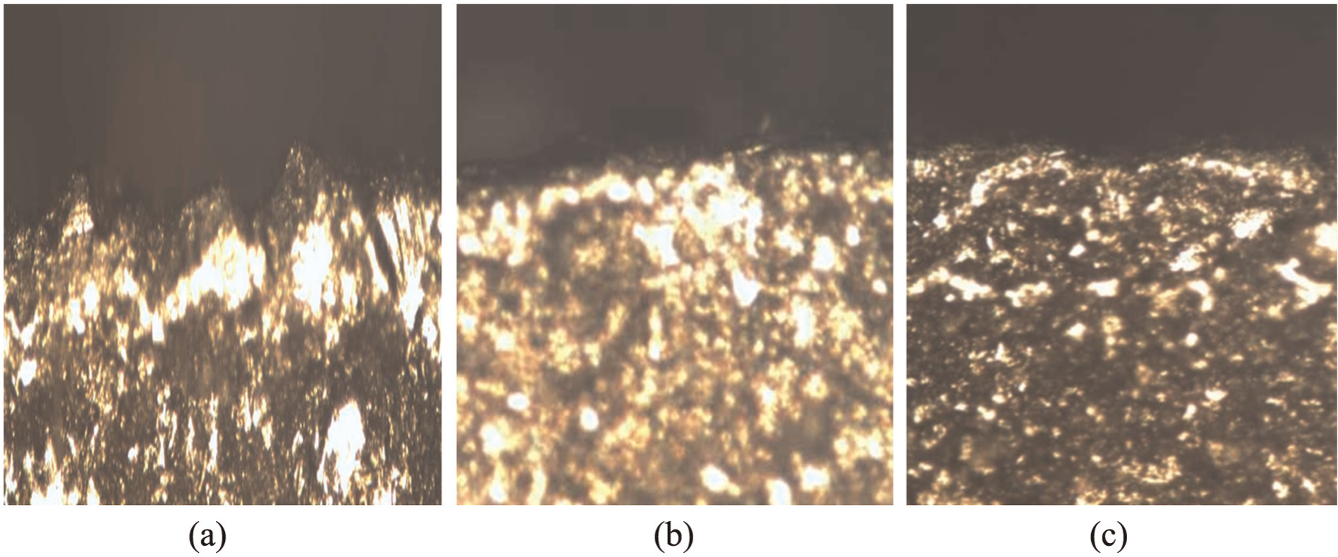
Photographs showing the thickness of deposited layers of machined surface using metallurgical microscope: (a) I = 3 A, duty factor = 40% and tool rpm = 0.00; (b) I = 3 A, duty factor = 40% and tool rpm = 250 and (c) I = 7 A, duty factor = 52% and tool rpm = 700.
Comparison of parameters
A comparison is made between stationary electrode EDM and EDDD for the obtained output parameters of Ra and Ca , which is shown in Table 4 for the at-a-glance appreciation of EDDD over stationary electrode EDM.
Comparison between obtained parameters’ stationary tool electrode EDM and EDDD.
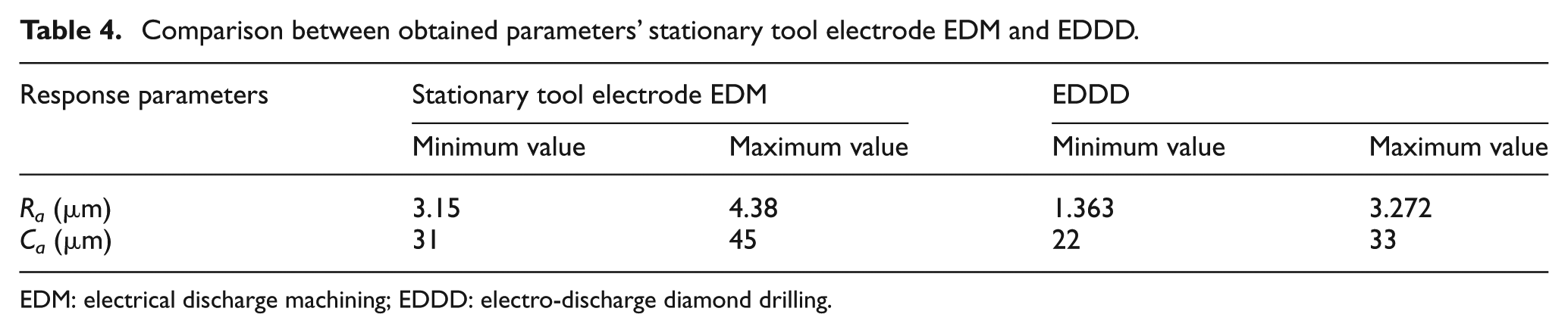
EDM: electrical discharge machining; EDDD: electro-discharge diamond drilling.
Conclusion
Based on the above conducted experimental study, the following conclusions are derived:
Although there has been a substantive improvement in conventional as well as nonconventional machining techniques, still the challenges for efficient, cheaper and reliable process for machining of tailor-made materials (advanced materials) do exist, which hampers the growth of aerospace industry.
HMPs such as ECAG, EDDG and EDAD have been used for machining of difficult-to-cut materials and reported for improved MRR and Ra . However, the use of metal-bonded diamond abrasive with EDM (EDDD) has not been traced for making of holes in the available literatures and that too for the analysis of Ra and Ca together.
In this study of EDDD, it is observed that Ra increases with an increase in gap current; however, it improves with an increase in duty factor and tool rpm. This is due to enhanced effective flushing at increased tool rpm as well as with the removal of re-casted thermal infested layers by diamond abrasive (bonded) of tool electrode.
It is observed that with EDDD, Ra varied from 1.363 to 3.272 µm against the stationary tool electrode EDM value of 3.15–4.38 µm which is very nominal and can be easily removed by fine polishing operation such as lapping.
The average circularity has increased very significantly with an increase in gap current at 40% duty factor, but improves with further increase in duty factor and tool rpm. The obtained values of Ca are found to be between 22 and 33 µm with EDDD process against the value of stationary electrode EDM of 31–45 µm, which is also very nominal. This is also credited to effective flushing of eroded materials with increasing tool rpm and abrasion action of bonded diamond grains of rotating tool electrode.
The improvement in the performance parameters of Ra and Ca using HMP of EDDD in nickel-based superalloy aerospace material has certainly given an edge for future researchers and industries so as to harness its potentiality for further research and for the use in industrial application.
Footnotes
Declaration of conflicting interests
The author(s) declared no potential conflicts of interest with respect to the research, authorship, and/or publication of this article.
Funding
The author(s) received no financial support for the research, authorship, and/or publication of this article.