
Abstract
As a new polishing method, bonnet polishing is suitable for polishing the curved surface due to its advantages in flexibility and adaptability of the polishing tool. In the polishing process, the contact state between the bonnet and the curved surface always changes. The traditional polishing tool path with equal interval will inevitably lead to over-polished areas and unpolished areas. In this article, a new tool path for bonnet polishing, which is called the revised Archimedes spiral polishing path, is proposed to ensure the physical uniform coverage of the curved surface in bonnet polishing. The path generation method is based on the modified tool–workpiece contact model and the pointwise searching algorithm. To prove the effectiveness of the revised path, two aspheric workpieces were polished along the traditional Archimedes spiral polishing path and the revised path, respectively. The roughnesses of the two workpieces are 10.94 and 10 nm, and the profile tolerances are 0.4097 and 0.2037 μm, respectively. The experimental results show that the revised path achieves lower roughness and surface tolerance than the traditional Archimedes path, which indicates that the revised path can achieve uniform physical coverage on the surface.
Keywords
Introduction
As the final procedure of the part surface fabrication, polishing plays an important role in surface processing. The surface quality is highly dependent on the polishing process. In the past, part surfaces were usually polished manually. With the development of the computer numerical control (CNC) system, the automation of the polishing process becomes possible.1,2 In recent years, some new polishing methods have been proposed, such as chemical mechanical polishing (CMP),3–5 magnetorheological polishing,6–8 electrorheological polishing,9–11 electrochemical mechanical polishing (ECMP),12–14 fluid jet polishing15–17 and plasma-assisted polishing.18,19 Bonnet polishing, which was first presented by King et al., 20 is also a new polishing method. Compared with the traditional rigid polishing tool, the bonnet polishing tool is flexible and soft; thus, it leaves few scratches on the surface and reduces subsurface damage. 21 Due to the flexibility of the polishing tool, bonnet polishing has the superiority in adapting to different kinds of surfaces. During the bonnet polishing process, the polishing tool contacts the surface and deforms. A contact area of a certain size is formed, where the material removal in polishing occurs. Since the contact area between the polishing tool and the surface can be controlled, deterministic material removal can be achieved.
In the previous studies on bonnet polishing, the main focus was on the tool influence function (TIF), the influence and optimization of process parameters, and the realization of deterministic polishing. Wang et al.22,23 studied the TIF and the contact area to achieve the deterministic material removal. They proposed three kinds of TIFs (sTIFt, sTIFd, and sTIFc). Wang et al. 24 also studied the influence of the process parameters on the residual error after polishing. Raster distance, Z-axis offset, inner pressure, H-axis speed, and precession angle were considered in their study. Feng et al. 25 simulated the removal function based on the velocity and pressure distributions. Compared with the study of Wang et al., Feng et al. took into account the concentration of the polishing slurry; thus, the accuracy of the obtained model was improved. However, in these studies, they chose to use simple geometric lines to verify the theories. Therefore, the planning of polishing path deserves further study.
In the existing studies on the planning of polishing path, although researchers have developed some planning methods for polishing process, these methods are not suitable to be applied to the curved surface in bonnet polishing. In Guo’s 26 study, the surfaces were polished by a rigid sub-aperture polishing tool following a traditional Archimedes spiral polishing path. Due to the rigidity of the polishing tool, the contact area between the polishing tool and the workpiece is almost constant. Thus, the physical uniform coverage of the polishing path can be easily achieved by the traditional Archimedes spiral with the same interval. Feng et al. 27 proposed a three-dimensional spiral path generation method that uses an iterative method to ensure uniformity in the space length of the adjacent circle of the spiral path. However, when a flexible bonnet polishing tool is used, the contact state varies along the tool path due to the curvature variation of the curved surface, thus the polishing paths proposed by Guo and Cheng et al. are not suitable for bonnet polishing. Takizawa and Beaucamp 28 proposed a new category of circular pseudo-random path. Although the experiments were carried out on the bonnet polishing platform, their research was applied only on a flat surface, and the contact area between the polishing tool and the workpiece was not taken into account. If this path generation method is performed on the curved surface and the changes of the contact area in polishing are considered, the difficulty and complexity of the path generation are greatly improved.
In this article, a new polishing path, which can achieve physical uniform coverage on the aspheric surface, is proposed. The path is based on the Archimedes spiral and called the revised Archimedes spiral polishing path. Generally, the path generation method takes into account the changes of the tool–workpiece contact area due to the curvature variation of the part surface.
The article is structured as follows. In section “Introduction,” the research background is introduced. In section “Contact model in bonnet polishing,” a modified tool–workpiece contact model is built. The generation method of the polishing path is proposed in section “Polishing path generation method.” A group of contrastive experiments and discussions are carried out in section “Experiments and discussions.” The conclusions are summarized in section “Conclusion.”
Contact model in bonnet polishing
Aspheric surface, which is a typical curved surface, is widely used in the optical industry and the medical industry. The polishing of aspheric surfaces has high application value. Therefore, the aspherical surface is selected as the workpiece.
Traditionally, the Archimedes spiral is considered to be one of the suitable polishing paths for a flat surface. Due to the characteristic of Archimedes spiral, the interval between adjacent polishing paths in the radial direction is same. Therefore, physical uniform coverage can be easily achieved on the flat surface. However, for the curved surface, especially aspheric surface, the contact area between the bonnet polishing tool and the surface varies along the radial direction. Therefore, the Archimedes spiral is not a suitable polishing path for bonnet polishing. In order to realize the physical uniform coverage on the workpiece surface, the radial interval of the polishing path should be adjusted according to the contact model.
Thus, the contact model of the bonnet polishing tool and the workpiece surface should be established first. In a previous study, the Hertz contact theory was used to analyze the contact area and the pressure distribution. 25 In bonnet polishing, the polishing tool is made of hyper-elastic material that can produce large deformation. Therefore, it is inaccurate to establish the contact model in bonnet polishing by the Hertz contact theory. Thus, a tool–workpiece contact model is established and modified by a mathematical modeling method.
Mathematical model
In the polishing process, when the polishing tool is set to an offset (δ), the tool and the workpiece surface form a contact area. When the polishing tool moves along the polishing path, a polishing area with a certain width is formed. Since the polishing path is generated based on the Archimedes spiral, the width direction of the polishing area, which influences the workpiece surface coverage, is consistent with the radial direction of the workpiece surface. Therefore, the tool–workpiece contact model can be expressed by the plane coordinate system composed of the radial direction (X-axis) and the workpiece symmetry axis (Z-axis). The tool–workpiece contact model can be simplified as the contact length model. The illustration of the contact length model is shown in Figure 1.
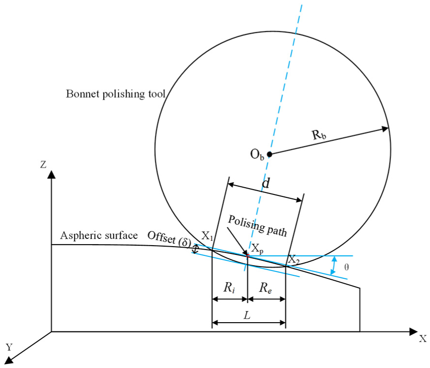
Contact length model.
The expression for the aspheric equation is
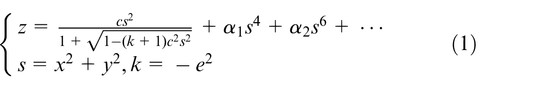
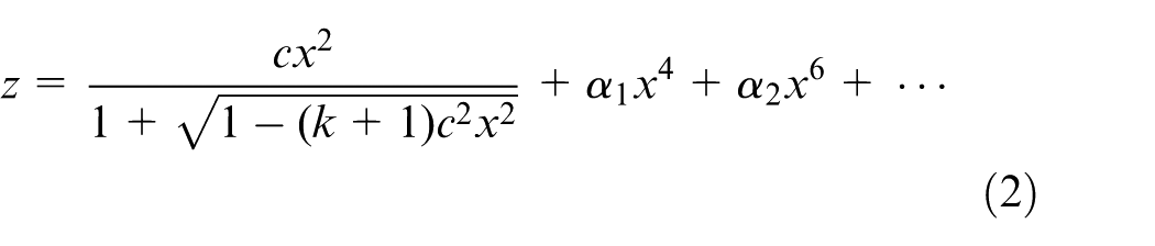
where c is the vertex curvature and e is the eccentricity. In this article, since the tool–workpiece contact model is simplified as the contact length model in the two-dimensional coordinate system, the aspheric equation can also be simplified into the two-dimensional form. Thus, equation (1) changes to
When the polishing tool passes through a certain point xp on the polishing path (as shown in Figure 1), the center of the polishing tool Ob is on the normal line passing through the point xp. The normal line at point xp can be expressed as
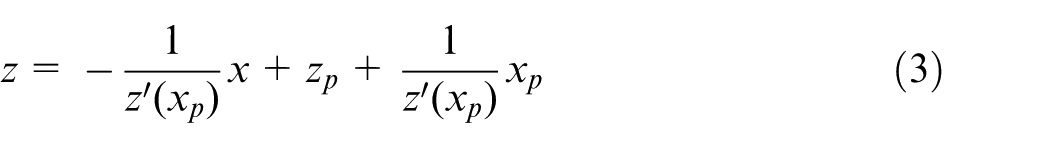
The distance from the polishing tool center Ob to the point xp on the polishing path is

where Rb is the radius of the bonnet polishing tool. The Cartesian coordinates of the center point Ob of the polishing tool is given by
The contour of the polishing tool can be expressed as
To solve the intersections of the polishing tool contour and the workpiece surface in the contact length model, a simultaneous equation of equations (2) and (6) is established as follows
Equation (7) can be solved by MATLAB, and the X-axis coordinate values of the intersections are x1 and x2, respectively. Here, we introduce the concept of the internal radius, the external radius, and the contact length, which is given by
where Ri is the internal radius, Re is the external radius, and L is the contact length. For the points on the polishing path, the values of Ri, Re, and L are different depending on the position.
Modified model
In fact, Ri, Re, and L in equation (8) are only the mathematical results, and its accuracy needs further verification. Therefore, the finite element analysis (FEA) method is used to analyze the tool–workpiece contact model (as shown in Figure 2). In FEA method, to reduce the analysis time and facilitate the acquisition of the contact area data, a flat surface is chosen as the workpiece.
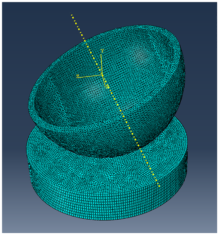
The FEA model.
The simulation conditions are shown in Table 1.
The simulation conditions.
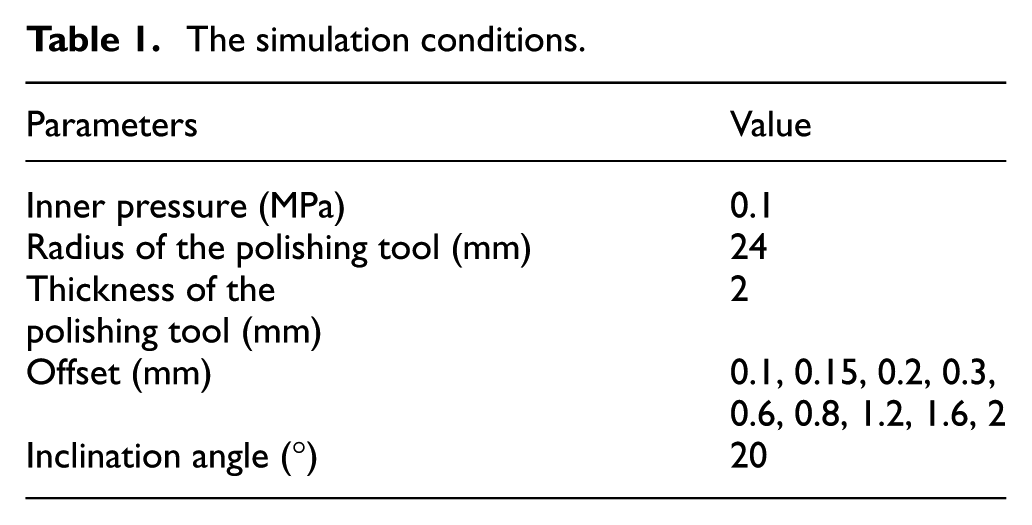
Since the value of the offset (δ) is not large during the actual polishing process, 0.1, 0.15, 0.2, and 0.3 mm are set as the offset. In addition, in order to ensure that the model obtained by the FEA method can also have higher accuracy when the offset is large, some large offset (0.6, 0.8, 1.2, 1.6, and 2 mm) are chosen. The simulation results of the FEA method are shown in Figure 3. Table 2 shows the comparison between the results of the FEA and the mathematical model calculation.
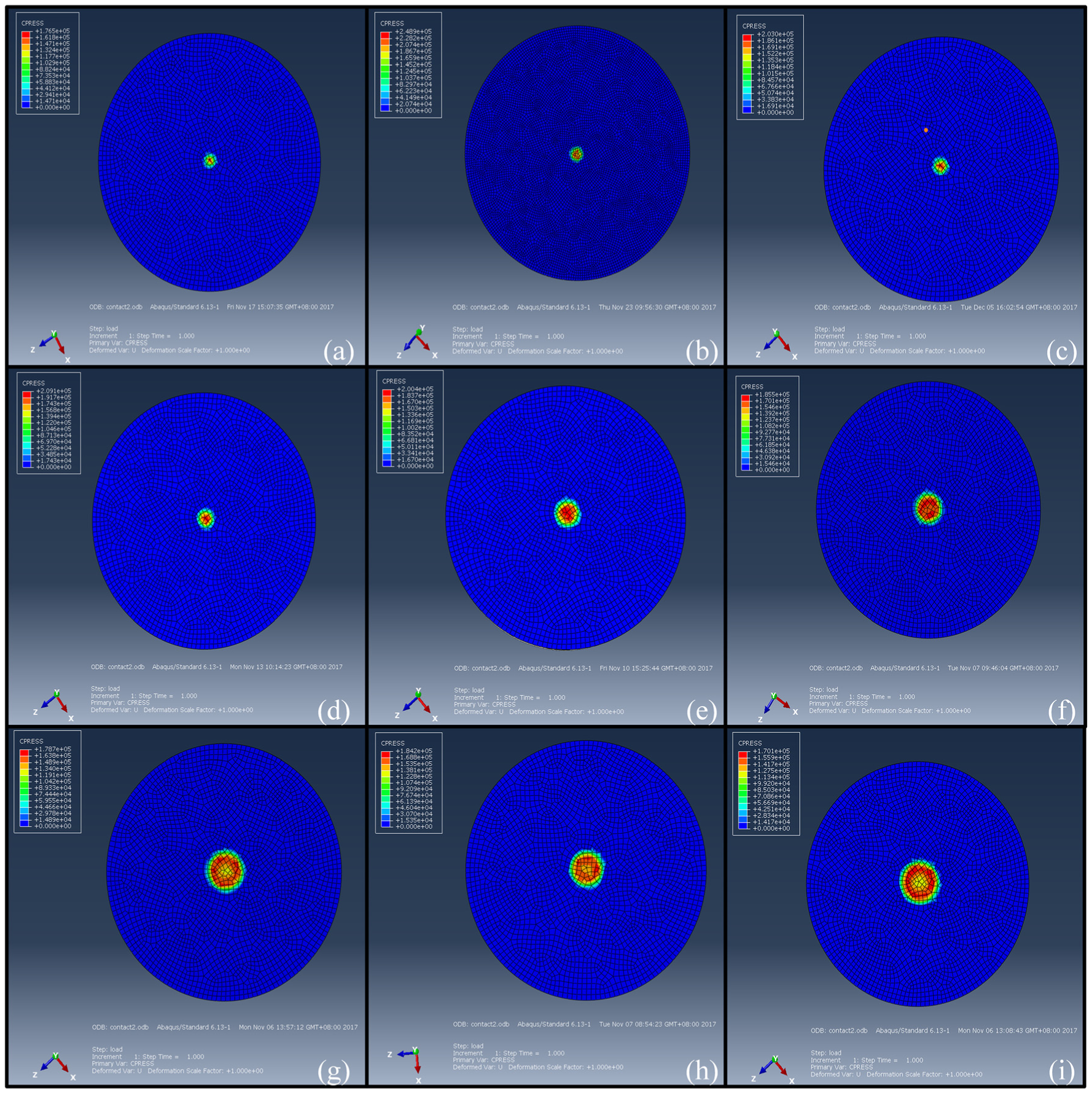
The FEA simulation results: (a) 0.1 mm, (b) 0.15 mm, (c) 0.2 mm, (d) 0.3 mm, (e) 0.6 mm, (f) 0.8 mm, (g) 1.2 mm, (h) 1.6 mm, and (i) 2.0 mm.
The contact length of the FEA and mathematical calculation results.
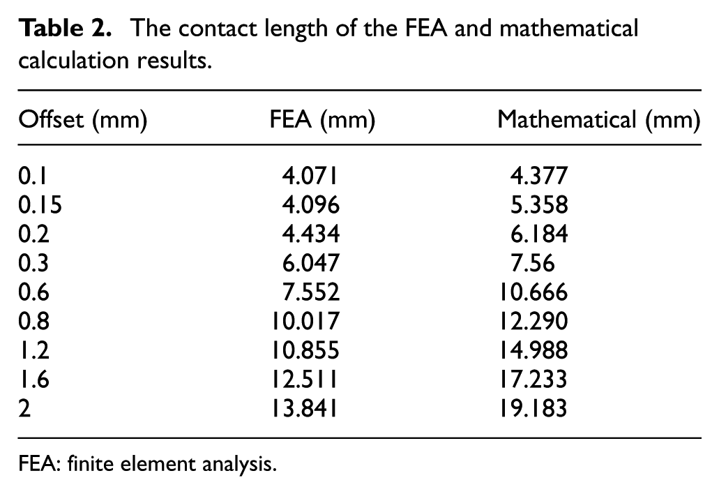
FEA: finite element analysis.
As shown in Table 2, the contact lengths obtained by the FEA method are smaller than the mathematical calculation results. As the offset increases, the deviation value becomes larger. The reason for this phenomenon is that the bonnet polishing tool has certain rigidity due to the inner pressured air when the offset is small. Therefore, the expected deformation at the edge of the contact area does not occur, which results in no contact or low contact pressure at the edge of the contact area. When the offset is small, this effect is not very obvious. When the offset is large, due to the hyper-elasticity of the rubber, the material in the contact area is squeezed and further shrinkage of the material occurs, which cause the higher pressure contact area moving outward from the contact center gradually (as shown in Figure 3(e)) and the further reduction in the contact area. The above two phenomena occur simultaneously during the contact of the polishing tool with the workpiece surface. When the offset is small, the former has greater influence, and the latter has greater influence when the offset is large.
The FEA results are processed by the curve fitting toolbox in MATLAB® and fitted in the
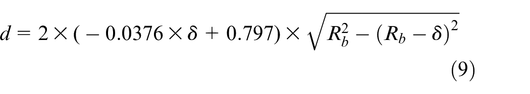
As shown in equation (9), the correction factor is
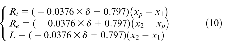
where Ri, Re, and L are the internal radius, external radius, and contact length obtained by the modified tool–workpiece contact model.
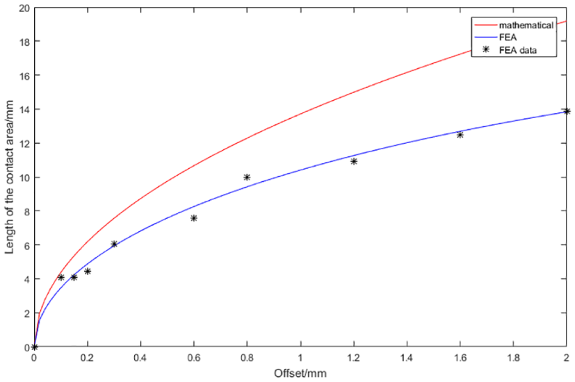
The fitting result of the contact length.
Polishing path generation method
Characteristics of the ideal polishing path
Taking the aspheric surface mentioned in section “Contact model in bonnet polishing” as an example, the curvature radius of the aspheric surface can be expressed as
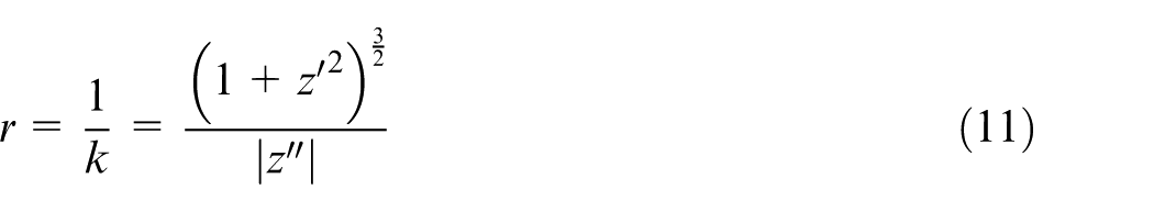
In the coordinate system shown in Figure 1, as the distance of the point on the aspheric surface from the workpiece symmetry axis (Z-axis) increases, the curvature radius of the point also becomes larger. When the offset is constant, a large curvature radius corresponds to a large length of d (as shown in Figure 1). At the same time, the variation of the tangent angle θ can also influence the contact length L. In order to confirm the variation trend of L, aspheric parameters and offset are given for quantitative analysis, where δ = 0.2, c = 1/300, k = −e2 = −3.3, α1 = α2 = 0, and the diameter of the aspheric surface is 100 mm. According to the calculation results of equations (7) and (8), as the distance from the Z-axis increases, the value of L becomes smaller.
If the Archimedes spiral is selected as the polishing path, as the contact length decreases, three polishing states occur (as shown in Figure 5(a)). These three states are defined as “overlapping,”“tangent,” and “interval.” The nearest distance between the edges of two radially adjacent polished areas is defined as the overlapping length (as shown in Figure 5(a)). When the overlapping length is zero, “overlapping,”“tangent,” and “interval” mean that the surface is over-polished, ideally polished, and some areas are unpolished. This is not an ideal polishing state. The ideal polishing state should be that the overlapping length of the two adjacent polishing area edges remains the same; in that case, the physical uniform coverage of the workpiece surface can be achieved (as shown in Figure 5(b)).
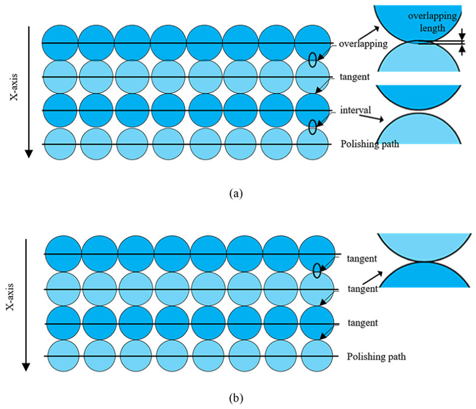
Polishing states: (a) three states of polishing and (b) ideal polishing states.
It should be noted that although the offset and aspheric parameters are given, it does not affect the universality of the path generation algorithm proposed in section “Polishing path generation method.” Thus, the description of the algorithm in section “Polishing path generation method” is also performed under this given set of offset and aspheric parameters.
Polishing path generation method
According to the above analysis, in order to achieve physical uniform coverage, the Archimedes spiral-based polishing path requires adjustment of the radial interval according to the calculated results of the modified tool–workpiece contact model. Due to the variation of the interval, the polishing path cannot be generated at once. It needs to be generated in an extension way by a searching algorithm. This searching algorithm is defined as the pointwise searching algorithm.
In the pointwise searching algorithm, the polishing path seed is first set before the generation of the polishing path. The polishing path seed is a series of points first set manually as the starting points of the path. As shown in Figure 6(a), the starting points have continuous radii and radians. The number of polishing path points is n (e.g. n is set as 50 in this article). As shown in Figure 6(b) and (c), the Cartesian coordinates are fitted and converted to polar form and the polar coordinates of these points are expressed in a new Cartesian coordinate system (the symmetry center point of the workpiece is the origin point). The curve in Figure 6(c) is defined as the first polishing path (PP1).
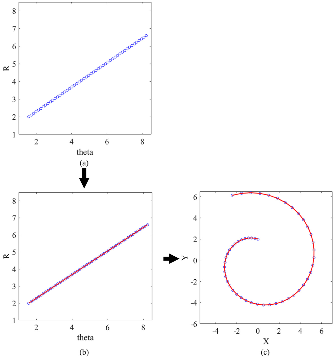
(a) Generation of the polishing path seed, (b) fitting of the polishing path seed, and (c) PP1.
After generating the first polishing path (PP1), the next step is to find the contact edge of the first polishing path. It should be noted that the contact edge represents the edge of the polished area formed by the polishing path. The contact edge includes the internal contact edge and the external contact edge. The internal edge refers to the edge that is close to the center of the workpiece, while the external edge refers to the edge that is far from the center of the workpiece. The external contact edge (PE1) of the first polishing path can be derived from equation (12)
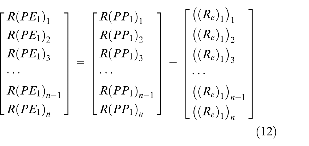
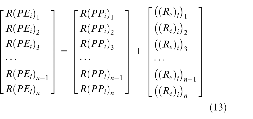
where R(PE1) n is the radius of the point on the external contact edge of PP1, R(PP1) n is the radius of the point on PP1, and ((Re)1) n is the external radius on PP1, which is calculated by the modified tool–workpiece contact model. Similarity, ((Re) i ) n can be derived as
After the PE1 is found, the next step is to find the points on PP2 based on the PE1. However, they cannot be solved directly by mathematical relations; thus, a pointwise searching algorithm is proposed to find the points on the next polishing path.
According to PEi, the internal contact edge (PIi+1) of the PPi+1 should have the required overlapping length (OL) with PEi. This relationship can be expressed as

In this algorithm, a tolerance (tol) is set to ensure that equation (14) has a solution. The tolerance is set to 0.002, and equation (14) changes to

Since the aspheric parameters are known in the actual polishing process (take the parameters in section “Contact model in bonnet polishing” as an example.), the contact length range can be estimated by equations (9) and (10). Therefore, the searching region (RCLmin, RCLmax) can be given to improve the efficiency of the searching algorithm. The increment of the searching process is ε, and the number of points in the next path is N. The flow chart of the pointwise searching algorithm is shown in Figure 7.
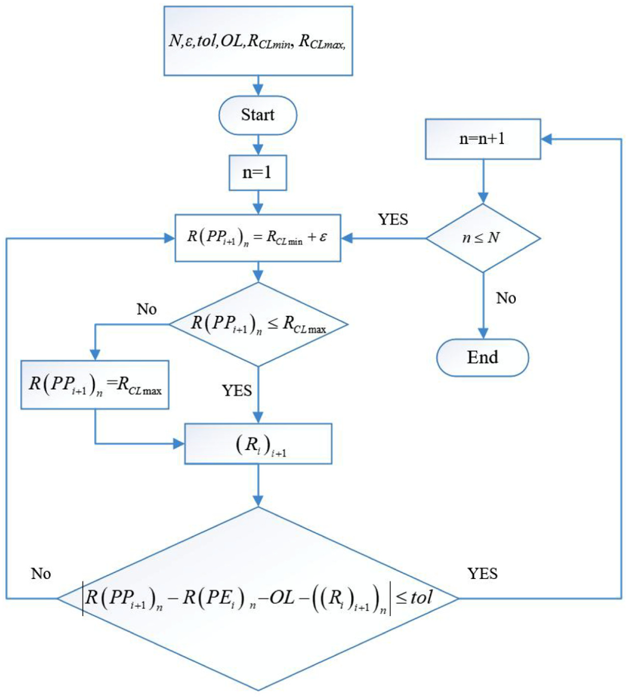
Flow chart of the pointwise searching algorithm.
In this article, N = 50, ε = 0.001, tol = 0.002, OL = 0, RCLmin = 4, and RCLmax = 4.5. After running the algorithm once and fitting the polishing path points, the PP2 can be obtained (as shown in Figure 8(c) and (d)).
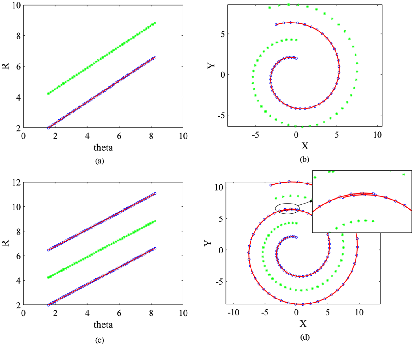
(a, b) Finding the PE1; (c, d) finding the PP2.
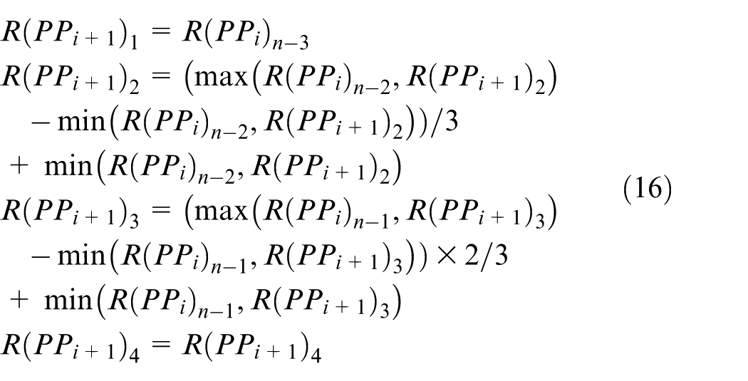
Since the selection of the polishing path seed is a manual choice, PP1 and PP2 cannot guarantee to be perfectly joined. Figure 8(d) shows that there is a gap between the two paths. Therefore, corrections must be made between two adjacent paths to ensure fluent connection. Thus, we choose the last four points of PPi and the first four points of PPi+1 for the correction process. The correction equation is as follows
A continuous fluent polishing path can be obtained by looping the pointwise searching algorithm and the correction process. The process terminates when the external contact edge of the polishing path exceeds the edge of the workpiece surface. After PPi is obtained, R(PEi) n can be obtained by equation (13). The maximum value (RPEmax) of R(PEi) n is compared with the radius of the workpiece surface boundary Rsurface. If RPEmax is less than Rsurface, the program continues to produce the next polishing path. Otherwise, it is concluded that the external contact edge of the polishing path has reached the boundary of the workpiece surface, and the generation process of the polishing path is completed. The polishing path on the X–Y plane is shown in Figure 9. Since the chosen aspherical parameters make the curvature change of the workpiece surface not obvious, it is difficult to observe the difference between the generated polishing path and Archimedes polishing path directly. Thus, a map of the polishing path and the contact area is given in Figure 10.
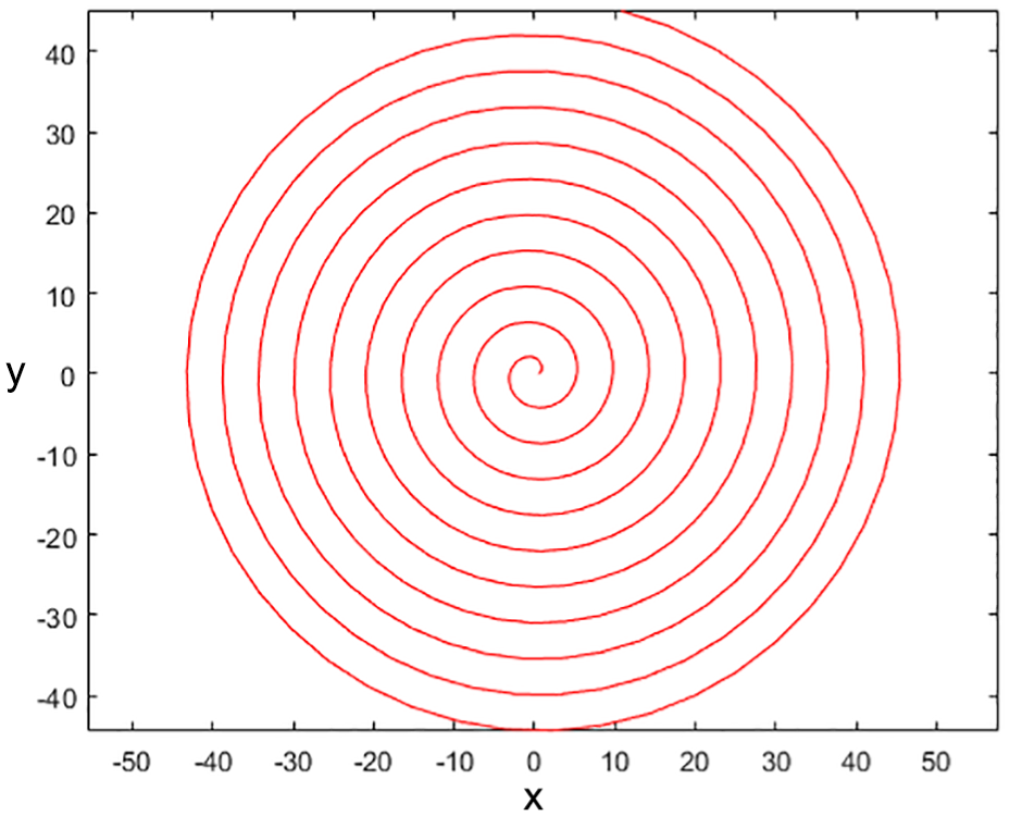
The revised Archimedes spiral polishing path.
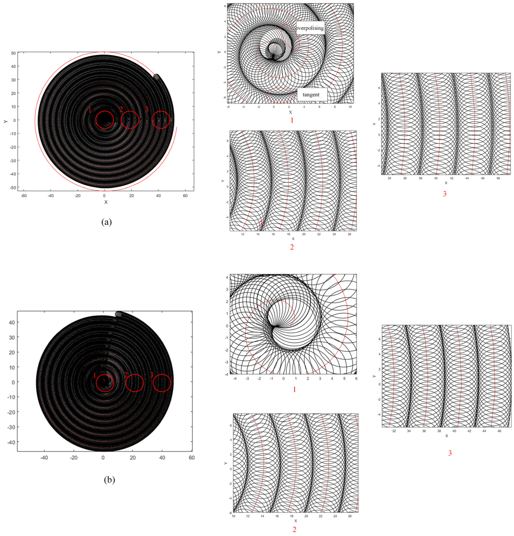
Maps of the polishing path and the contact area: (a) Archimedes path and (b) revised path.
Since the density of the contact area is high, Figure 10 can be clearly seen in the partial enlargement figures (right side of Figure 10(a) and (b)).
As shown in Figure 10(a), during the first few laps of the Archimedes polishing path, the over-polishing occurs. With the extension of the polishing path, the radial adjacent contact edges are tangent to each other. After a few laps, the interval arises between the contact edges. With the extension of the polishing path, the interval becomes larger. This result is consistent with the analysis in Figure 3.
Compared with Figure 10(a), the over-polishing and the interval are greatly improved in Figure 10(b). The contact areas remain almost tangent from beginning to end. This proves the effectiveness of the pointwise searching algorithm.
After generating the polishing path on the X–Y plane, the polishing path projects to the aspheric surface.
Experiments and discussions
Experimental setup
In order to verify the effectiveness of the revised path, a group of comparative experiments were carried out. Figure 11(a) shows the five-axis machine tool used in the experiment. Figure 11(b) shows the pre-polished aspheric workpiece used in the experiment. The aspheric parameters are the same as mentioned in section “Contact model in bonnet polishing.”
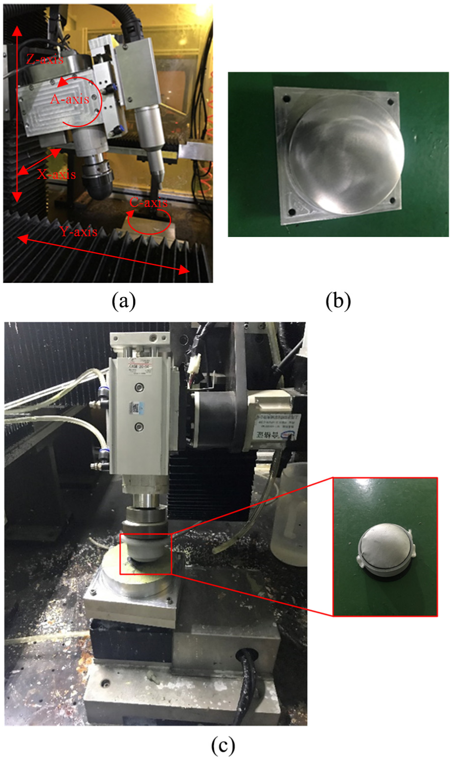
(a) Polishing machine, (b) pre-polished aspheric workpiece, and (c) polishing process.
The other main experimental parameters are shown in Table 3.
Experimental parameters.
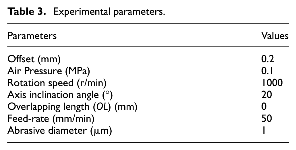
As shown in Table 3, the offset of the bonnet polishing tool is 0.2 mm. The pressure inside the bonnet polishing tool is 0.1 MPa. The rotation speed of the polishing spindle is 1000 r/min. The inclination angle of the polishing spindle relative to Z-axis is 20°. In order to compare the two polishing paths, the overlapping length is set to zero. The feed-rate of the bonnet polishing tool is 50 mm/min. The average particle size of diamond grinding paste used in the experiment is 1 μm. The polishing tool is covered with polished cloth during the process (as shown in Figure 10(c)).
The machine tool motion parameters can be calculated by the inverse kinematics. 29 The bonnet polishing tool can realize movement along the polishing path through the five-axis linkage of the machine. The polishing process is shown in Figure 10(c). During the polishing process, the X-, Y-, and Z-axis can realize translational motion. The A-axis controls the inclination angle of the polishing tool, and the C-axis controls the rotation of the workpiece. Movement during machining is achieved by the combination of the translational motion and the rotational motion.
Results and discussions
The workpieces polished along two paths are shown in Figure 12(a) and (b), respectively.
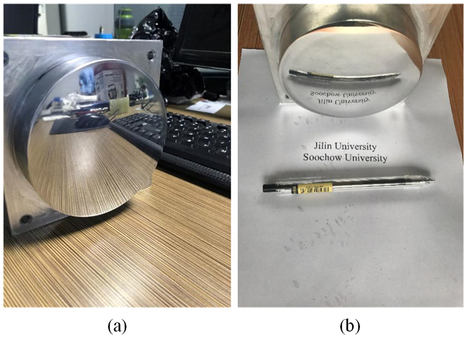
Workpieces after polishing: (a) Archimedes path and (b) revised path.
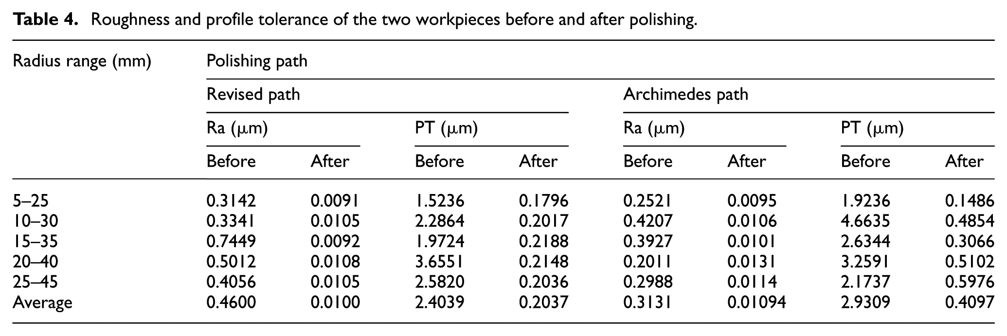
After polishing, the workpiece surfaces were measured by a Taylor Hobson profiler. Five paths with the same radial length were selected as the measuring paths. Each path has a length of 20 mm, and the measuring paths are distributed in different radius ranges (5–25 mm, 10–30 mm, 15–35 mm, 20–40 mm, and 25–45 mm). The measuring results are shown in Table 4 and Figure 13.
Roughness and profile tolerance of the two workpieces before and after polishing.
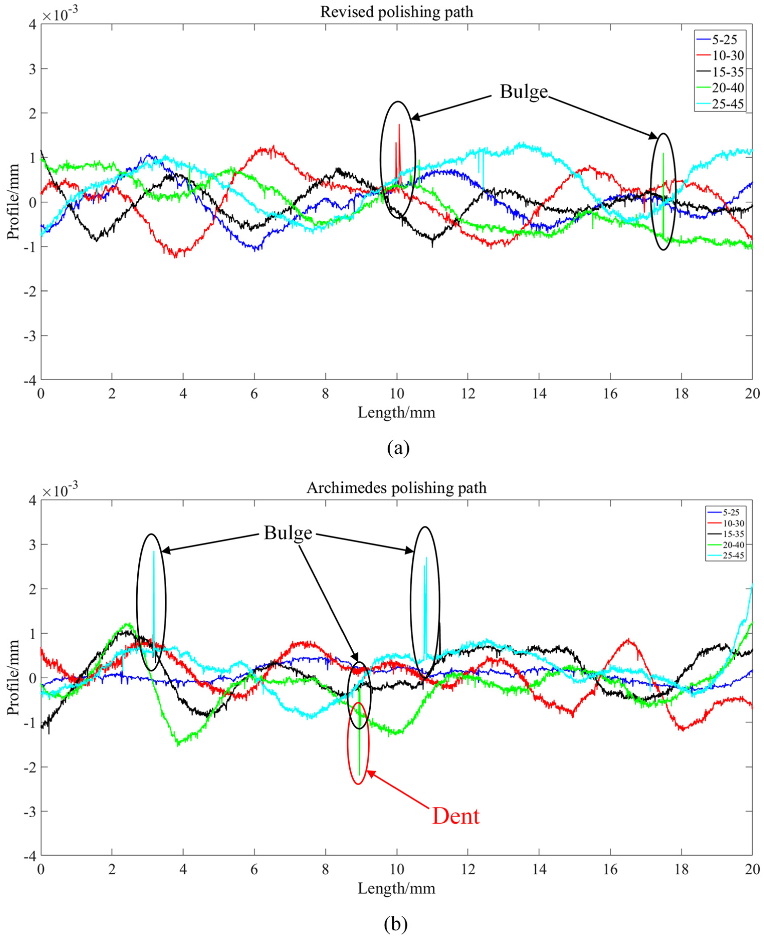
Profiles of the two workpieces: (a) revised path and (b) Archimedes path.
As shown in Table 4, the average roughnesses of the workpieces processed by the revised path and the Archimedes path are 10 and 10.94 nm, respectively. The average roughnesses of the two workpieces are similar. However, the roughnesses of the revised path at different measurement regions are closer and more stable than those of the Archimedes spiral polishing path. The roughnesses of the Archimedes spiral polishing path are lower in the first few measurement regions, and the roughnesses are higher in the last two measurement regions. It is probably because of the inhomogeneous material removal and the unpolished area. To verify the conjecture, the profile tolerances of the two sample pieces were measured.
The profile tolerances and the profiles of the two workpieces are shown in Table 4 and Figure 13, respectively. The average profile tolerance of the revised and traditional Archimedes spiral polishing path is 0.2037 and 0.4097 μm, respectively. It indicates that the material removal of the revised path is more homogeneous than the traditional Archimedes spiral polishing path. The profiles of the two workpieces at different measurement regions in Figure 13 also show that the profiles of the workpiece processed by the revised Archimedes spiral polishing path are more consistent.
According to Figure 13(b), when the measurement region approaches the workpiece surface boundary, the fluctuation of the profiles increases. In the first measurement region, the material removal on the adjacent two paths caused by the rotation of the polishing tool is superimposed. According to the removal profile of a rotating polishing tool, 30 after the superposition of two profiles, the difference between the maximum removal rate and the minimum removal rate becomes smaller. Therefore, the PT value of this part is smaller and the fluctuation of the profile is small. In the second and third measurement regions, the interval between the contact edges appears. The surface quality is worse than the first region. In the last two measurement regions, bulges and dents arise. This is because the interval becomes larger and more obvious than the beginning. The surface is not completely polished in these areas. Thus, the unpolished areas obviously reduce the surface quality. The bulges correspond to the unpolished areas, and the dents are caused by scratches on the surface.
Conclusion
To realize the physical uniform coverage of the aspheric surface in bonnet polishing, a new polishing path and its generation method are proposed in this article. The generation method is based on the modified tool–workpiece contact model and the pointwise searching algorithm. The following conclusions are achieved.
First, the modified tool–workpiece contact model is derived and developed from the FEA method. According to the FEA results, a correction factor is added to the mathematical contact model for the quantitative analysis of the contact length. The contact model contributes to the generation of the polishing path.
Second, the polishing path generation algorithm, which is called the pointwise searching algorithm, is developed for the revised Archimedes spiral polishing path. The pointwise searching algorithm can adjust the radial interval of the polishing path according to the surface curvature. The revised path can realize homogeneous material removal and physical uniform coverage on the surface.
In order to verify the effectiveness of the revised path, a group of comparative experiments were carried out. Compared with the Archimedes spiral polishing path, the workpiece processed by the revised Archimedes spiral polishing path has a relatively lower roughness and lower profile tolerance. In addition, the surface profile has fewer bulges and dents caused by unpolished areas and scratches. Therefore, the revised path is effective in improving the homogeneity of material removal in polishing, which helps to reduce the roughness and profile tolerance of the polished surface.
According to the results, the roughness of the surface can be further improved using proper polishing liquid. The TIF can be further studied to realize lower profile tolerance.
Footnotes
Declaration of conflicting interests
The author(s) declared no potential conflicts of interest with respect to the research, authorship, and/or publication of this article.
Funding
The author(s) disclosed receipt of the following financial support for the research, authorship, and/or publication of this article: This study was supported by the Basic Research Program of Jiangsu Province (BK20150330), the Chinese National Natural Science Foundation (51505312), and the Chinese Postdoctoral Science Foundation (2015M571800).