
Abstract
In order to achieve good functional performance on surface texture with high processing efficiency, this article proposes a vertical continuous precession polishing method for aspheric lenses based on the analysis of abrasive trajectories on contact region. First of all, by analyzing the relative motion between bonnet tool and workpiece, the motion model of particle trajectories on contact region was established. Then, comparison and analysis of abrasive trajectories with various polishing methods were carried out. Moreover, a vertical continuous precession polishing method for aspheric lenses and related experiments were presented. The results revealed that the texture on contact zone of aspheric lens polished by vertical continuous precession was approximately random and uniform, which is appropriate for polishing curved surfaces continuously. In addition, the contact zone on different polishing spots with various curvatures can be controlled by adaptive algorithm, and the simulated results validated the feasibility of the proposed polishing method for aspheric lenses.
Introduction
Bonnet polishing technology is widely used in aspheric lens polishing recently, owing to the controllability of inner pressure of bonnet and good agreement between the flexible bonnet and workpiece. The most crucial feature of this technology is the application of classic continuous precession motion, which would lead to random and uniform particle trajectories in flat polishing. 1 However, classic continuous precession is not available in aspheric polishing due to the change of direction of local normal of various polishing spots on the workpiece surface. Therefore, sub-step precession method was presented by Walker et al. 2 to address this problem, but new questions came up that the polishing efficiency and control accuracy of the polishing process would both be affected by this method. For abovementioned reasons, it is essential to find a novel method which would polish aspheric lenses efficiently and has good functional performance on surface texture as well.
As a commonly used evaluation index for machining control method, particle trajectories on the surface (i.e. texture) are generated by the motion of abrasives, which is closely related to the quality of workpiece. In optics, in particular, it has been reported that periodic and regular trace on the surface of workpiece is an important reason for introducing the mid-spatial frequency errors, 3 which can degrade optical performance.4–11 Therefore, the distribution of the particle trajectories in polishing process is estimated to be random and uniform. For this reason, research on abrasive trajectories in polishing process is necessary. Wu et al. 12 analyzed the relative motion between polishing tool and workpiece in Computer Controlled Optical Surfacing to get the abrasive traces on the surface of workpiece. Moreover, they associated the quality of polished surface with the particle trajectories and ultimately found that the particle trajectories and polishing quality can be optimized by adjusting the relative cutting speed v, rotation angle of common tangent of particle trajectories β, the changing rate Ω β of β in relation to the polishing time t, the speed ratio I and radius of pitch circles R. Zhao et al. 13 introduced the researching methodology of uniformity of abrasive traces, showed detailed derivation of motion model of abrasives for each common polishing method, and pointed out that most of the existing research reports on the calculation of particle trajectories are based on the assumption that the abrasives are fixing firmly on the polishing tool and the workpiece surfaces have an ideal plane shape. Su et al. 14 studied the formation mechanism of within-wafer non-uniformity (WIWNU) of material removal in Chemical Mechanical Polishing and found that the WIWNU of material removal is caused by the non-uniformity of motion of abrasives on wafer surface, which explained that the mechanical action of material removal is mainly the mechanical action of abrasives. Pan et al. 15 built the kinematic model of abrasive trajectories in plane polishing based on cluster magnetorheological (MR) effect. Finally, polishing experiments with optimized parameters was carried out, which verified the simulation results. Sousa et al. 16 focused on optimizing the polishing process of porcelain stoneware tiles by analyzing kinematics of a single abrasive and highlighted the importance of kinematic parameters. However, little attention has been paid on abrasive trajectories on contact region in bonnet polishing.
This article proposes a novel polishing method for aspheric lenses based on analysis of abrasive trajectories on polishing spot. Section “Motion modeling of abrasive trajectories on contact zone” of this article describes the motion model of particle trajectories on contact zone. Section “Comparison of abrasive trajectories with various polishing methods” analyzes the abrasive trajectories on contact zone with various polishing methods. On the basis of the results of comparison and the processing property of aspheric lenses, section “Vertical continuous precession for aspheric polishing” proposes a vertical continuous precession, and makes related simulations to validate the availability of this novel method for aspheric polishing.
Motion modeling of abrasive trajectories on contact zone
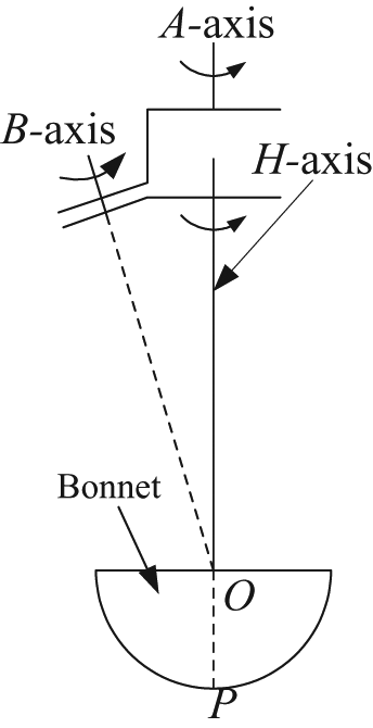
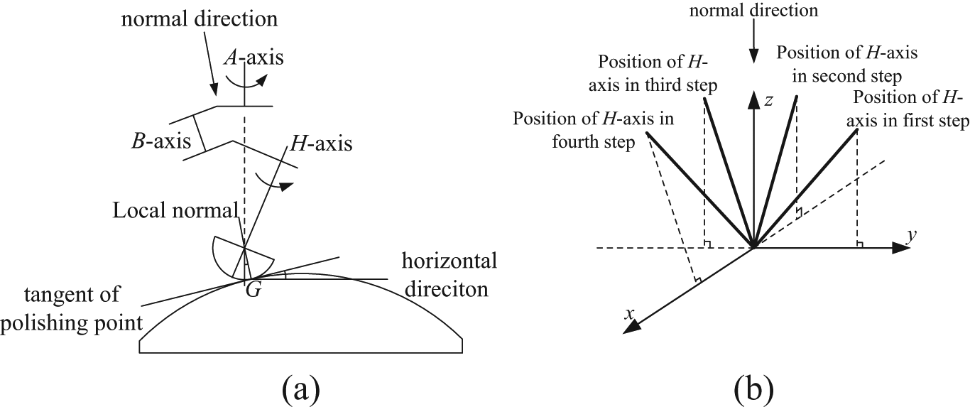
In bonnet polishing process, workpieces are usually polished with continuous precession, which is schematically shown in Figure 1. 17 For example, the bonnet tool revolves around its own axis (H-axis) with an angular velocity ωH and simultaneously rotates with an angular velocity ωA around the normal of polishing spot (same direction to A-axis when polishing flat optics). The definitions of other symbols in the figure are listed as follows: R is the radius of bonnet, α is the included angle between A- and H-axis, O is the bonnet centre, Oz is the centre of contact zone, M is a random point on bonnet, and D is the length of OOz, which is the difference between radius of bonnet R and compression of bonnet h. It has been reported that 1 the texture of workpiece polished with this method was random and uniform, which is appropriate in polishing stage. Figure 2 shows the kinematical diagram of Figure 1. O-xyz is a basic coordinate system, of which the original point is the bonnet centre O. k is the position vector of H-axis of bonnet tool. β is the positional angle of H-axis, which is the included angle between projection of H-axis on plane Oxy and x-direction.
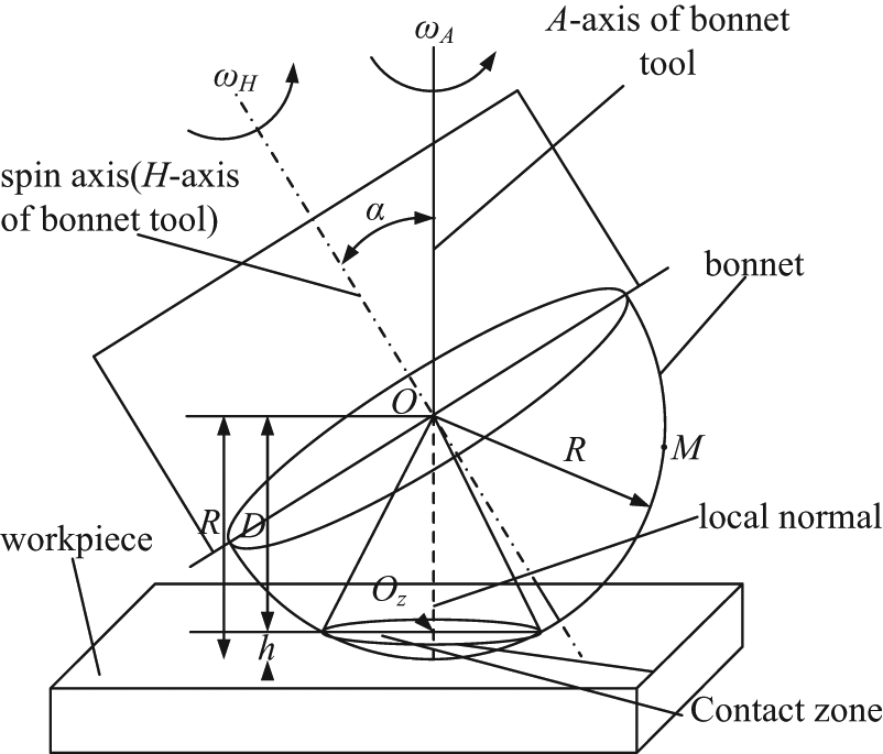
Principle of bonnet polishing with precession.
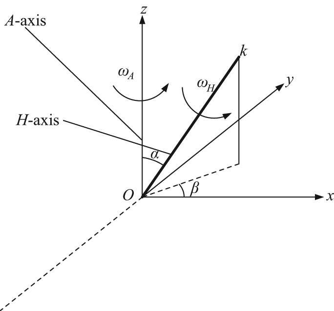
Kinematical diagram of bonnet polishing with precession.
It is assumed that the particles are embedded uniformly on the polishing pad, which adheres to the surface of bonnet and moves along with the bonnet tool. Thus, the abrasive trajectories on contact zone are generated by the motions of particles on the bonnet. M (x, y, z) (see Figure 1) is supposed to be a random point on the bonnet. When the bonnet tool polishes the workpiece with precession, the motion of point M can be resolved into two parts, that is, rotating around A-axis and H-axis of bonnet tool, respectively. Consequently, the path of M can be calculated by two steps:
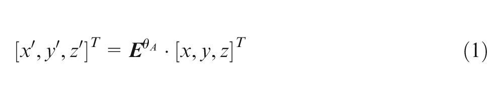
When rotating around A-axis, the position of M can be obtained by using rotational transfer matrix 18
where (x, y, z) are the original coordinates of point M, (x′, y′, z′) are the coordinates of point M after rotation, and
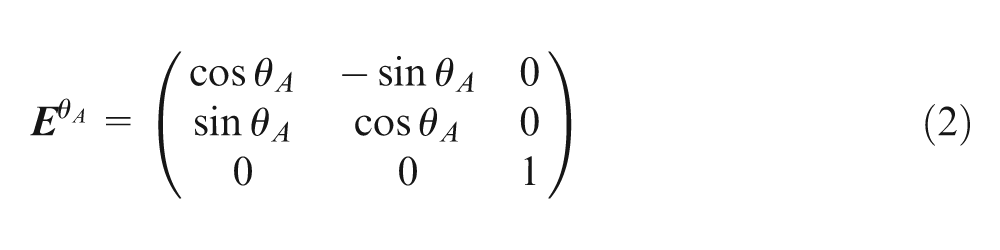
where θA is the rotation angle
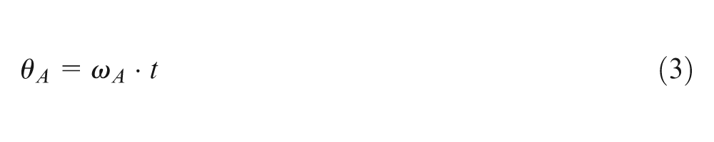
where ωA is the angular velocity of A-axis and t is the rotation time.
2. When rotating around H-axis, the position of M can be obtained by using rotational transfer matrix 18
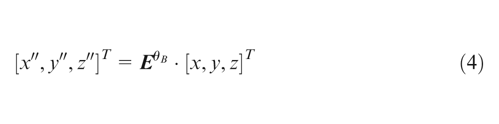
where (x, y, z) are the original coordinates of point M, (x″, y″, z″) are the coordinates of point M after rotation, and
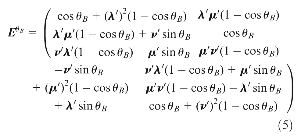
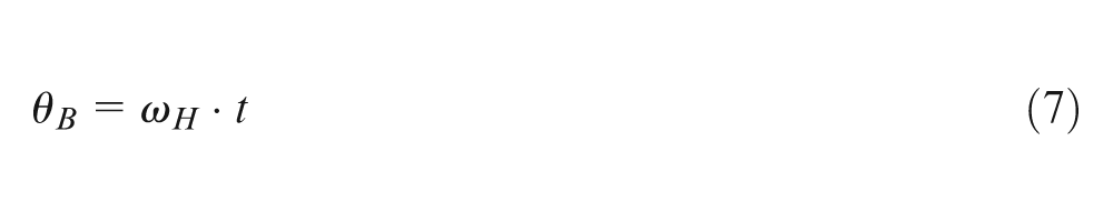
where θB is the rotation angle and
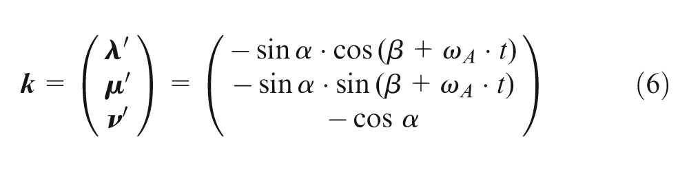
where α is the angle between H- and A-axis, and β is the included angle between the projection of H-axis on plane xOy and x-axis
where ωH is the angular velocity of H-axis.
As previously mentioned, bonnet tool polishes workpieces with simultaneous rotation of A- and H-axis. Thus, on the basis of the derivation in previous paragraphs, particle trajectories on contact zone of a random point M on the bonnet can be calculated as 18
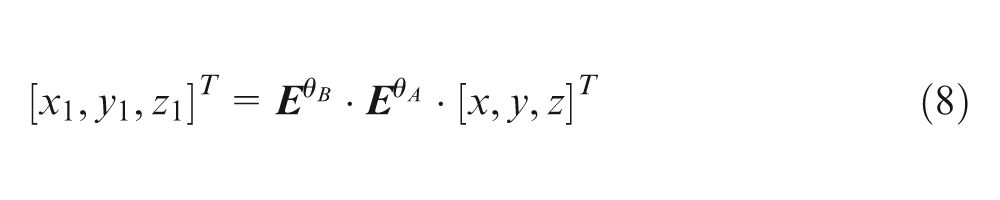
where (x 1, y 1, z 1) are the position of point M after rotation of A-axis and H-axis of bonnet tool, and equation (8) is supposed to be the motion model of the abrasive trajectories on contact zone in bonnet polishing.
Comparison of abrasive trajectories with various polishing methods
Figure 3 schematically shows the structural diagram of bonnet tool which is mainly composed of three axes: A-axis, B-axis, and H-axis, and all of them intersect in the centre of the bonnet O. In addition, the direction of A-axis is vertical and the included angle between B and A-/H-axis is always 45°. It is obvious that there are kinds of polishing methods (i.e. various combinations of rotation axes) that can be implemented owing to the feature of multi-axis of bonnet tool. Therefore, comparison of particle trajectories with different methods is presented in this section.
Structural diagram of bonnet tool.
Vertical polishing of flat optics
According to the principle of bonnet polishing shown in Figures 1 and 2, the vertical polishing method is defined that only A-axis of bonnet tool rotates in the polishing process. Assuming that the parameters are given as follows: radius of bonnet R = 80 mm, the compression of bonnet h = 0.25 mm, the angular velocities of H-axis and A-axis are
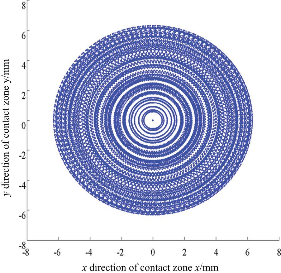
Abrasive trajectories on contact zone of vertical polishing.
As shown in Figure 4, the distribution of abrasive trajectories of vertical polishing shows periodicity and regularity. It is composed of several concentric circles, of which the centre is the projection of bonnet centre on polishing spot. Obviously, this method is not applicable to polishing, of which the texture is supposed to be random and uniform.
Inclined polishing of flat optics
As shown in Figures 1 and 2, the inclined polishing method is defined that only H-axis of bonnet tool rotates in the polishing process. In addition, there is an included angle between H- and A-axis, and the spatial position of H-axis changes along with the value of angle β. Assuming that the parameters are given as follows: the angular velocities of H-axis and A-axis are ωH = 1000 r/min and ωA = 0, respectively; two positional angles of H-axis are β = 0° and 90°, respectively; and values of other parameters are the same as that in section “Vertical polishing of flat optics.” Similarly, according to the motion model (see equation (8)), the simulated abrasive trajectories on contact zone of inclined polishing are shown in Figure 5.
Particle trajectories on contact zone of inclined polishing: (a) β = 0 and (b) β = 90°.
Figure 5(a) and (b) show the particle trajectories on contact zone with two positional angles of H-axis. It is clear that the abrasive trajectories of inclined polishing are symmetrically distributed along the projection of H-axis on the plane xOy, which also shows periodicity and regularity. Different from abrasive trajectories of vertical polishing, inclined polishing is distributed in single direction, which is determined by the value of angle β.
Flat optics polishing with classic continuous precession
The concept of classic continuous precession was first proposed by Bingham et al., 1 which means the bonnet tool revolves around its own axis and simultaneously rotates with the local normal of polishing spot. In Figures 1 and 2, it is defined that both H-axis and A-axis rotate when polishing a flat workpiece (this is because all directions of local normal of polishing spots on a flat are the same as the direction of A-axis). Assuming that the parameters are given as follows: the angular velocities of H-axis and A-axis are ωH = 1000 r/min and ωA = 100 r/min, respectively, values of other parameters are the same as that in section “Vertical polishing of flat optics.” Then, based on the motion model shown in equation (8), the simulated particle trajectories on contact zone of classic continuous precession can be obtained in Figure 6.
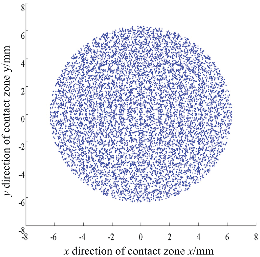
Abrasive trajectories on contact zone of flat polishing with classic continuous precession.
As shown in Figure 6, the distribution of the abrasive trajectories on contact zone of flat polishing with classic continuous precession is perfectly random and uniform, which is important for polishing process. However, as mentioned in previous paragraph, the bonnet tool has to rotate with the local normal of polishing spot while revolving around its own axis to achieve classic continuous precession. And it cannot be realized by this structure of bonnet tool when polishing aspheric lenses, because the direction of local normal changes with the curvature of polishing spot.
Sub-step precession for aspheric polishing
Since aspheric lenses may not be polished with classic continuous precession, sub-step precession method was raised by Zeeko Ltd to address this problem. 2 The core idea of this method is to divide the classic continuous precession into several inclined polishing steps with various directions. The principle of sub-step precession method is shown in Figure 7.
Principle of polishing aspheric lenses by sub-step precession method: (a) single step of sub-step precession and (b) positions of H-axis in 4-sub-step precession.
Figure 7 schematically shows a random point G on aspheric surface polished by a 4-sub-step precession process. As can be seen in Figure 7(a), there is a single sub-step, which is the same as inclined polishing aforementioned in section “Inclined polishing of flat optics.” In addition, the positions of H-axis of bonnet tool in 4-sub-step process vary with the positional angles of H-axis. As shown in Figure 7(b), the angles of the four positions of H-axis are 0, 90°, 180°, and 270°, respectively.
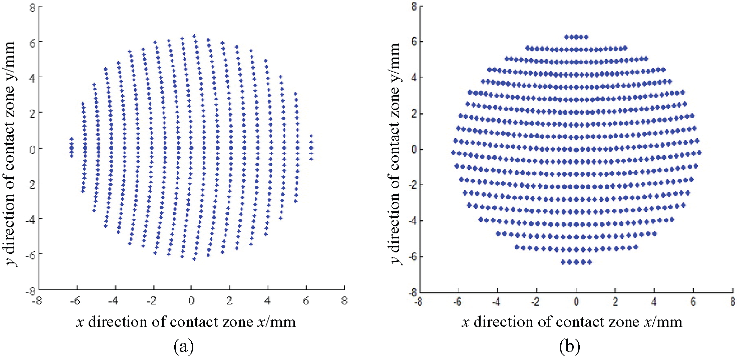
Assuming that the parameters are given as follows: the angular velocities of H-axis and A-axis are ωH = 1000 r/min and ωA = 0, respectively, and an 8-sub-step process is compared with a 4-sub-step one. The positional angles β of H-axis of bonnet tool are 0, 90°, 180°, and 270° in the 4-sub-step process. By contrast, the position angles β of H-axis of bonnet tool are 0, 45°, 90°, 135°, 180°, 225°, 270°, and 315° in the 8-sub-step process. The values of other parameters are the same at that in section “Inclined polishing of flat optics.” According to the motion model of particle trajectories (see equation (8)), the simulated abrasive trajectories on contact zone of sub-step precession (4 and 8 steps) can be obtained in Figure 8.
Abrasive trajectories on contact zone of flat polishing with sub-step precession: (a) 4-sub-step process and (b) 8-sub-step process.
It is indicated in Figure 8 that, in terms of non-periodicity and irregularity, the sub-step precession in abrasive trajectories on contact zone is better than vertical polishing and inclined polishing, but not as good as that of classic continuous precession for flat polishing. In addition, the more steps used in the sub-step precession process, greater is the observable non-periodicity and irregularity of the abrasive trajectories. Although the precession can be realized by using sub-steps for aspheric polishing, it is possible that the efficiency and accuracy of polishing process would be decreased accordingly.
After the comparison, continuous precession in particle trajectories on the contact zone of flat optics polishing shows the best performance, that is, randomness and uniformity, which are desired in polishing process. In contrast, vertical and incline polishing exhibit apparent periodicity and regularity, which should be eliminated. As to sub-step precession, the abrasive trajectories feature a mixture of random and periodic properties. However, all of the polishing methods mentioned previously can be applied in aspheric polishing except continuous precession, because of the change of normal directions of different polishing spots on aspheric lenses and the technical requirement of continuous precession that the spin axis has to rotate around the normal of polishing spot.
Experimental validation
In order to validate the motion model of abrasive trajectories on contact zone in bonnet polishing presented in previous paragraphs, polishing experiments for various methods were carried out. Figure 9(a) shows the experimental setup; the bonnet tool is composed of three axes: A-axis (driven by Motor A), B-axis (equipped with encoder, and operated by hand), and H-axis (driven by Motor H). All of them intersect in the centre of the bonnet. Besides, the direction of A-axis is vertical and the included angle between B and A-/H-axis is always 45°. Thus, experiments of different polishing methods aforementioned were conducted, that is, inclined polishing (only H-axis rotates in polishing process), plane polishing with continuous precession (A- and H-axis rotate simultaneously), and sub-step polishing (see to Figure 7, only H-axis rotates). All the results are shown in Figure 9(b)–(d)).
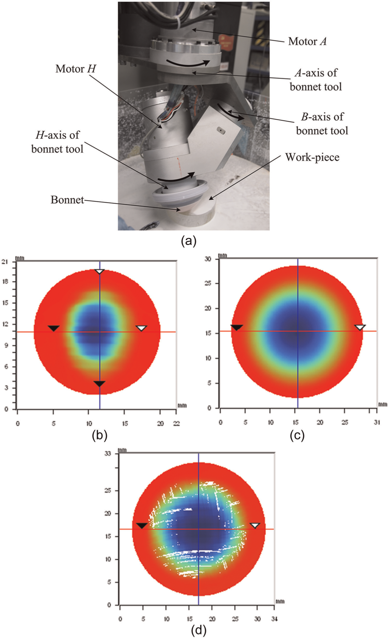
Experimental results: (a) experimental setup, (b) incline polishing (β = 270°), (c) continuous precession polishing, and (d) sub-steps precession polishing.
Comparing the experimental results with the corresponding simulations (Figure 9(b) with Figure 5(b), Figure 9(c) with Figure 6, and Figure 9(d) with Figure 8(a)), it is clear that the periodicity and regularity of particle trajectories (see the blue parts in the figures) in the experimental results are consistent with the simulated results. This validates the motion model of abrasive trajectories proposed in the aforementioned section.
Consequently, based on analysis of motion model of abrasive trajectories on contact region, a vertical continuous precession polishing method was proposed, which processes aspheric lenses efficiently by continuous motion of bonnet tool in order to achieve good functional performance on surface texture of the workpiece.
Vertical continuous precession for aspheric polishing
Figure 10 schematically shows the principle of aspheric polishing with vertical continuous precession, which is defined as that H-axis rotates on its own axis, while revolving around A-axis of bonnet tool in whole polishing process. The difference between vertical continuous precession and classic continuous precession is that the spinning H-axis rotates around A-axis in the former method but rotates around local normal of polishing spot in the latter one. Moreover, the compression of vertical continuous precession has to be controlled in the polishing process. It is clear that vertical continuous precession is the same as classic continuous precession when polishing flat workpiece because all the directions of local normal of polishing spots are the same as that of A-axis. However, in aspheric polishing, as the direction of local normal changes with the position of polishing spot, the classic continuous precession is not available, which is different from the vertical continuous precession. Obviously, the polishing efficiency of vertical continuous precession is at least as high as that of classic continuous precession. Thus, in the following sections, simulated experiments related to polished surface texture were carried out to analyze the application of vertical continuous precession in aspheric polishing.
Principle of aspheric lens polishing with vertical continuous precession.
Control of polishing spot
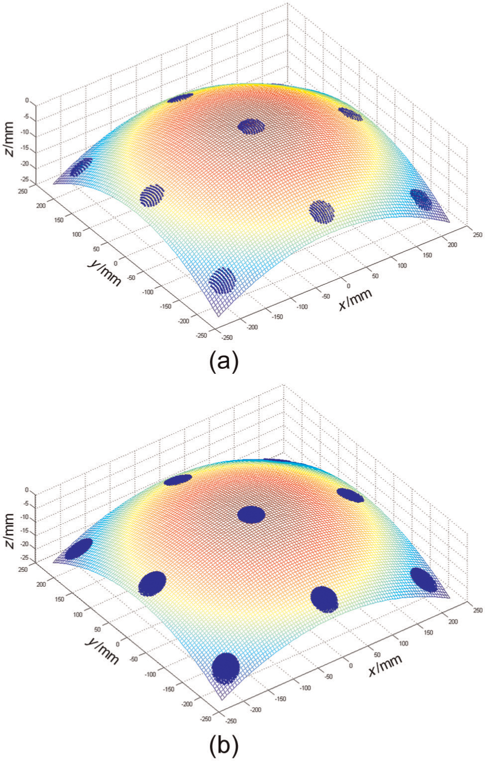
Assuming that an axis-symmetric aspheric lens is polished with vertical continuous precession, and the processing parameters are given as follows: the size of workpiece is 460 mm × 460 mm (x×y), the radius of bonnet equals 80 mm, the vertical compression of bonnet for every polishing spot is 2 mm, the included angle between A- and H-axis is 25° and the positional angle of H-axis β = 0°. Besides, in order to reduce the calculated amount, only 9 polishing spots distributed with zonal features were chosen on the aspheric surface. In this case, the simulated results are shown in Figure 11. Figure 11(a) shows a top view of the aspheric surface, in which different colors represent different relative heights when referring to the vertex of the workpiece surface.
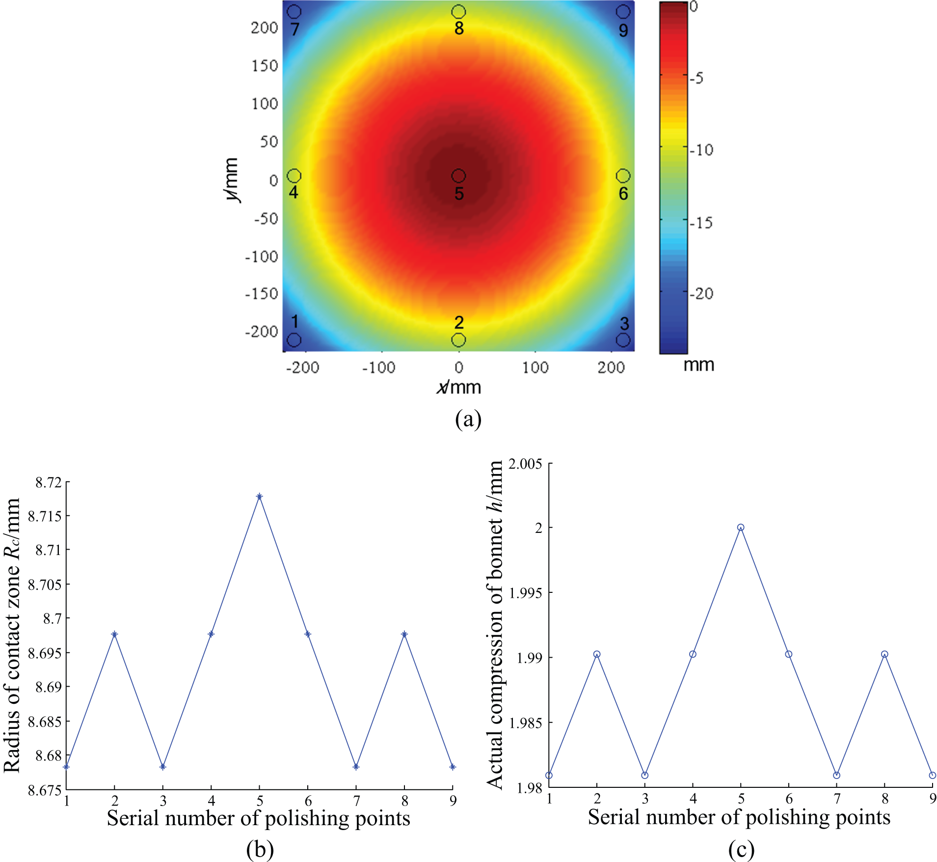
Radius of contact zone and actual compression of bonnet in vertical continuous precession method: (a) distribution of polishing spots on aspheric surface (top view), (b) radius of contact zone, and (c) the actual compression of bonnet.
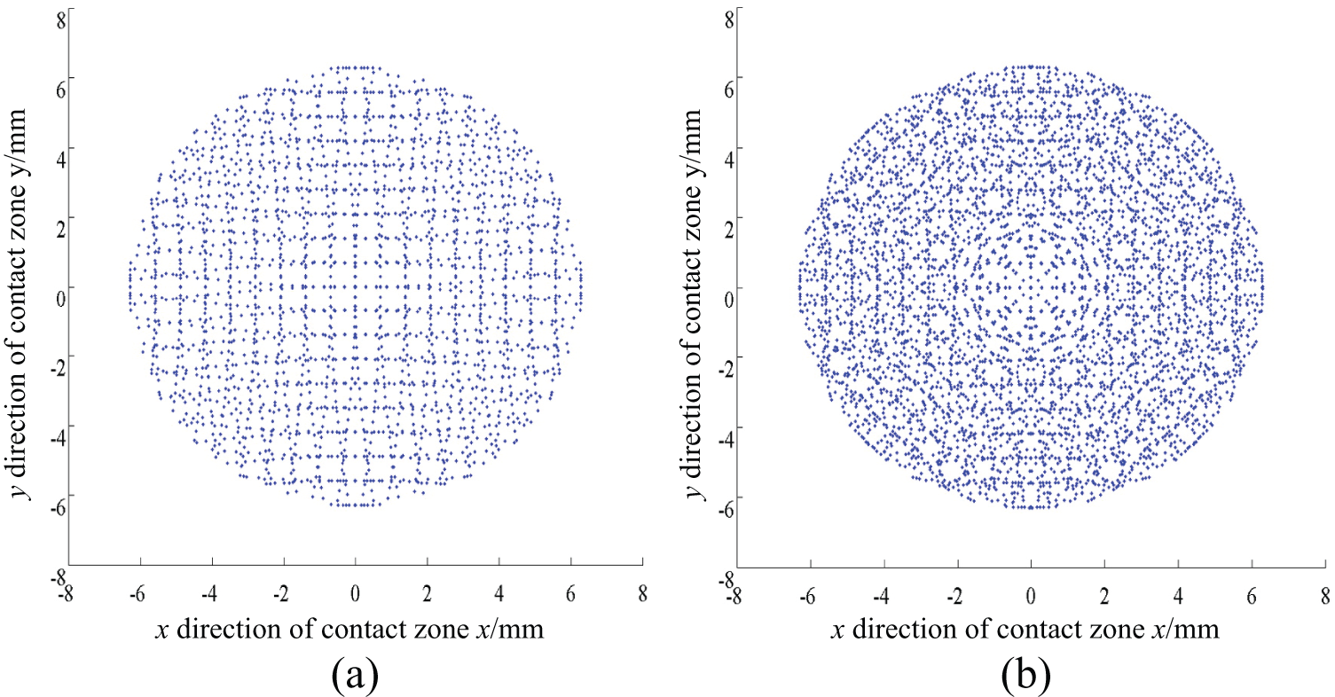
As shown in Figures 10 and 11, because of the variation of curvature in different locations of the aspheric surface (result in the inclined angle, i.e., γ in Figure 10), the actual compression of bonnet varies with the position of polishing spots (see Figure 11(c)). This leads to the variation of radius of contact zones (see Figure 11(b)), which is not desirable in polishing. To uniformize the radius of contact regions and actual compressions of bonnet, an adaptive algorithm was applied to the simulated polishing process, and the radius of contact zone and the actual compression of bonnet before and after control is shown in Figure 12.
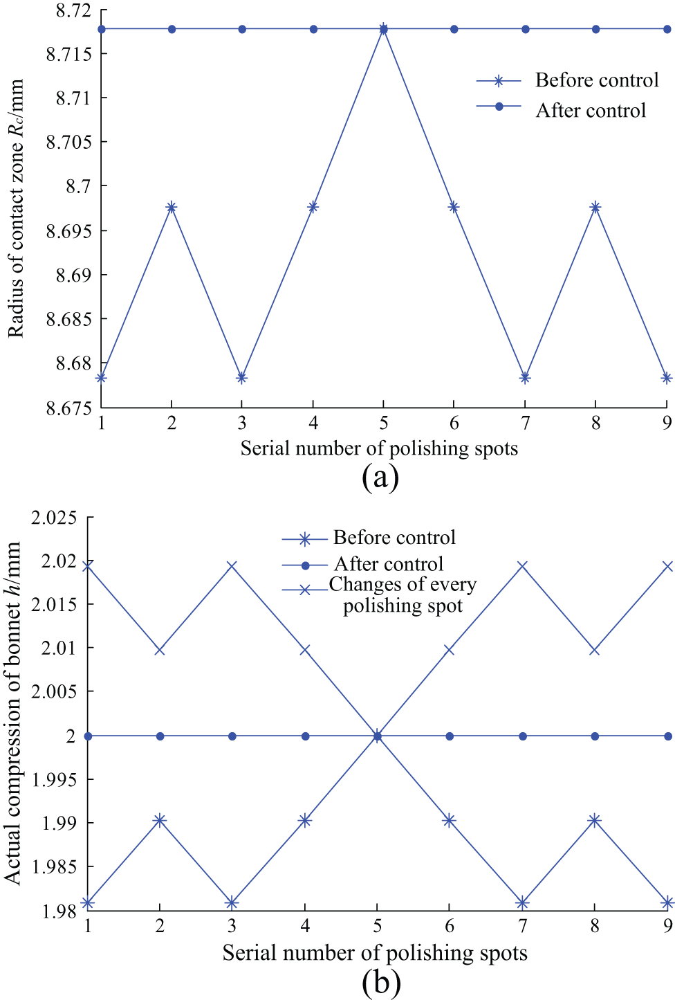
Radius of contact zone and actual compression of bonnet before and after control: (a) radius of contact zone before and after control and (b) actual compression of bonnet before and after control.
As shown in Figure 12, it is obvious that both the radius of contact zone and the actual compression of various polishing spots on aspheric surface are consistent with the utilization of adaptive algorithm, which is desirable in aspheric polishing. After that, the analysis of particle trajectories on contact zone of vertical continuous precession is also required.
Abrasive trajectories on contact zone of vertical continuous precession
Based on the simulation abovementioned, particle trajectories on contact zone (after control of algorithm) of aspheric polishing were analyzed according to the motion model given in equation (8). Comparison of abrasive trajectories between inclined and vertical continuous precession polishing for aspheric surface was also obtained. The additional parameters are given as follows: the angular velocity of H-and A-axis are 1000 r/min and 0 r/min, respectively, in inclined polishing, and the corresponding angular velocity in vertical continuous precession are 1000 r/min and 100 r/min, respectively. The simulated results are shown in Figure 13.
Comparison of abrasive trajectories on contact zone between inclined and vertical continuous precession polishing: (a) inclined polishing of aspheric lens and (b) vertical continuous precession of aspheric lens.
Figure 13(a) and (b) show the abrasive trajectories of inclined and vertical continuous precession for aspheric polishing, respectively. Similar to inclined polishing for flat surface, the abrasive trajectories of incline polishing for aspheric lenses show periodicity and regularity, which should be avoided in polishing process. In contrast, the abrasive trajectories of vertical continuous precession for aspheric lenses reveals approximate randomness and uniformity, which are desirable.
Combining the simulated results from polishing spots and abrasive trajectories on contact zone of vertical continuous precession for aspheric lenses, it is apparent that: first, aspheric lenses can be polished with the proposed method continuously, which would effectively improve the control accuracy and the polishing efficiency (reducing processing time when compared to sub-step polishing method). Meanwhile, the uniformity of polishing spots can be achieved by the utilization of adaptive algorithm. Second, the surface texture of aspheric lenses polished with vertical continuous precession shows approximate randomness and uniformity, which is consistent with that of flat workpiece polished with classic continuous precession. In view of the performance on polishing efficiency and surface texture, vertical continuous precession method has bright prospect in aspheric manufacturing.
Conclusion
In order to achieve good functional performance on surface texture with high processing efficiency, this article proposes a vertical continuous precession polishing method for aspheric lenses based on the analysis of abrasive trajectories on contact region. In summary, the following conclusions are obtained:
Based on the relative motion between bonnet tool and workpiece in polishing process, the motion model of abrasive trajectories on contact zone was established. According to the motion model, analysis of abrasive trajectories with vertical polishing, inclined polishing, classic continuous precession, and sub-step precession was completed and experimentally validated.
By using the aforementioned motion model, the vertical continuous precession polishing method was proposed, based on the analysis of abrasive trajectories on contact region. First, the concept of vertical continuous precession was introduced. After that, simulated experiments about control of polishing spot and abrasive trajectories on contact zone were carried out to analyze the application of vertical continuous precession in aspheric polishing. As a result, both the radius of contact zone and actual compression of various polishing spots on aspheric surface are consistent with the utilization of control algorithm, which is desired in aspheric polishing. Moreover, the abrasive trajectories of vertical continuous precession for aspheric lenses reveal approximate randomness and uniformity, which are also important. Both simulated results demonstrate that the proposed method is appropriate for aspheric polishing.
Characterization of abrasive trajectories by the observable non-periodicity and irregularity as used in this article is a qualitative approach based on previous investigation. A quantitative dimension of “random” and “uniform” should be analyzed in future work; moreover, the removal characteristics of vertical continuous precession should also be studied before its application.
Footnotes
Declaration of conflicting interests
The authors declare that there is no conflict of interest.
Funding
This work was funded by LPMT, CAEP (No. KF13011), the National Important Science and Technology Special Projects of China (no. 2013ZX04001000-206), and Fundamental Research Funds of Xiamen University (no. 201212G011).