
Abstract
In this article, a research was conducted on the effects of the precession mechanism error on polishing spot, and it is helpful for optimizing the mechanism. In the research, an error model was built to analyze the error caused by gravity and polishing force on the accuracy of the mechanism, finite element analysis and MATLAB simulation were carried out based on the error model to estimate the effects, and, finally, an experiment was conducted to test the simulation result. It was found that the precession mechanism error mainly has an influence on the position of polishing spot in x and y directions. Simulation results show the position error up to −698.7 µm in y direction and −88.5 µm in z direction under free condition, while in polishing process, the error decreased 588.4 µm in y direction and 26.7 µm in z direction. The size of single polishing spot decreased 2.67%, while the size of four-step tilted polishing spot and continuous polishing spot increased 0.66% and 6.78%, respectively. Through experiment, it can be seen that the size of the polishing spot is also affected by the inflation pressure in bonnet tool, rigidity of bonnet tool, tool clamping error, and mechanism processing error.
Introduction
The development of optical technology has rapidly increased the requirements for high-precision optical elements, especially aspheric optics. However, machining high-accuracy aspherical optics is still not that easy because of its specific geometrical shape. Many kinds of advanced polishing methods have been developed to achieve high-precision aspherical optics in recent decades, such as computer-controlled small tool polishing, 1 ion beam finishing, 2 stressed lap polishing, 3 magnetorheological finishing,4,5 fluid jet polishing, 6 and bonnet polishing.7,8 Bonnet polishing uses an inflated spherical membrane tool which makes it perfectly fit itself to the aspheric form. 9 Compared with other sub-aperture polishing methods, it can deliver much higher polishing efficiency10,11 and has now been widely used in polishing segment mirrors used in telescopes. 12 In addition, it has a correction capability of low frequency errors and mid-spatial frequency errors through adopting a series of tools.13,14
Bonnet polishing adopts a unique precession movement mode. Its rotation axis is tilted to the surface’s local normal, at an angle of typically 10°–25° (called “precession angle”). The aim of precession is to achieve better surface texture and avoid zero removal in the center of the tool influence function. To date, researches on bonnet polishing were almost focused on the fields of removal function,15–17 process control,18,19 polishing parameters, 20 edge effects, 21 and so on. Few attentions were paid to explore the effects of precession mechanism error on the polishing quality. The accuracy of the precession mechanism plays an important role in keeping the stability of the tool influence function, as it connects with bonnet tool directly. Therefore, it is necessary to analyze how the precession mechanism error affects the tool influence function so that the mechanism can be optimized reasonably.
This article mainly considers the effects of mechanism deformation caused by gravity and polishing force on the accuracy of the mechanism and analyzes its impacts on the polishing quality. First, the precession mechanism error was modeled on the basis of its geometry architecture. Then, the value of the deformation was achieved through finite element analysis (FEA). After that, the position error and the size error of the polishing spot were calculated through the deformation results and the error model. At last, an experiment is conducted to test the error model and follows with the conclusion.
Error model
Figure 1 shows the precession mechanism of bonnet polishing. The mechanism consists of swing arm A, swing arm B, and spindle. They form three axes: A-axis, B-axis, and H-axis, which intersect at the center O0 of bonnet tool. The angle between B-axis and H-axis is 45°, and the one between A-axis and H-axis is variable, which is controlled by B-axis motor. Figure 2 shows the precession motion, the bonnet tool covered with a suitable polishing surface, which is rotated about its axis by the tool-spindle (H-axis). It attacks the surface at an angle to the local normal to the surface (the “precession angle”) and precesses around this normal in discrete steps. 23 Abrasives on polishing surface polish the workpiece in each step and generate a Gaussian removal function on the surface with random and uniform texture.22,24
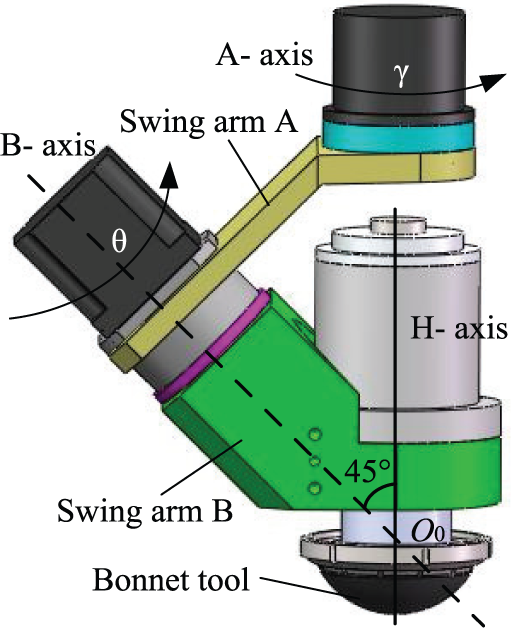
Precession mechanism.
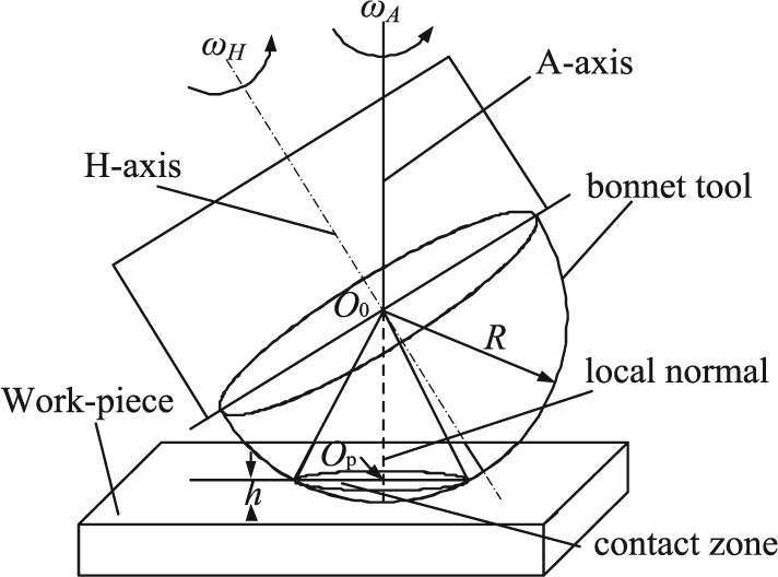
Precession polishing for planar workpiece. 22
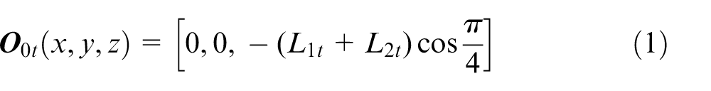
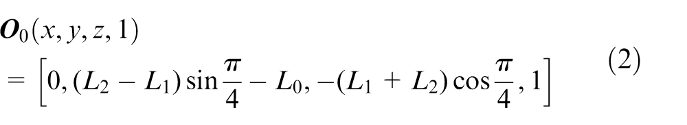
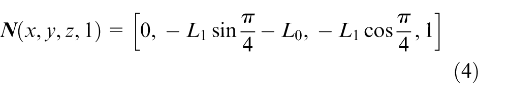
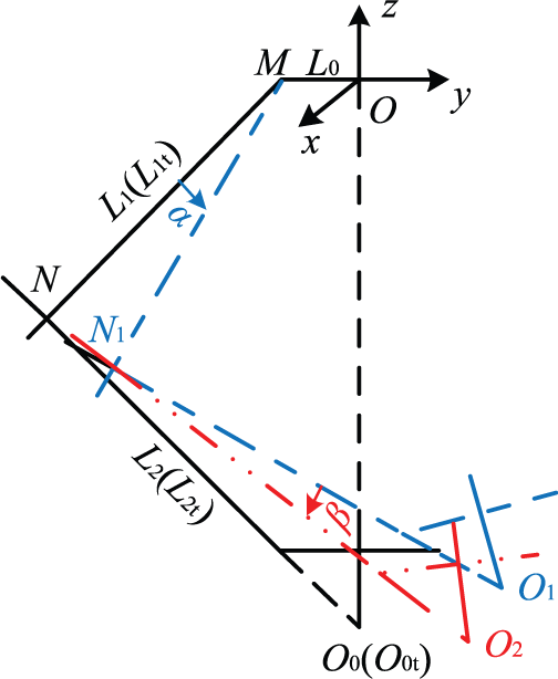
In polishing process, the length of swing arms and the precession angle have usually been altered due to its deformation caused by the gravity and polishing force. The error model of the mechanism has been built as shown in Figure 3. In Figure 3, a coordinate system O-xyz is built, O is the intersection of A-axis and swing arm A, L1t and L2t are theoretical lengths of two swing arms, L1 and L2 are actual lengths of two swing arms, α is the error angle of swing arm A, and β is the error angle of swing arm B. The coordinates of point O0t (theoretical position of bonnet tool), point O0 (position of bonnet tool as the error angles do not exist), point M, and point N in O-xyz are given below

Error model of the mechanism.
The coordinates of O1 and N1 in O-xyz


where
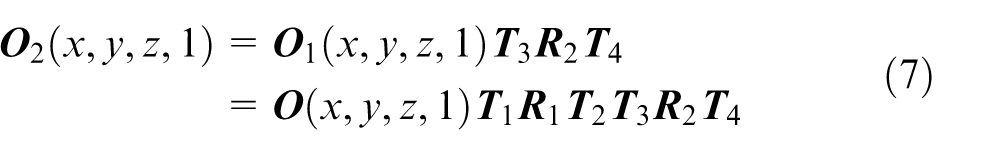
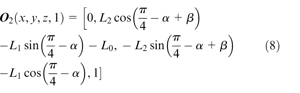
Similarly, the coordinates of point O2 in O-xyz
where
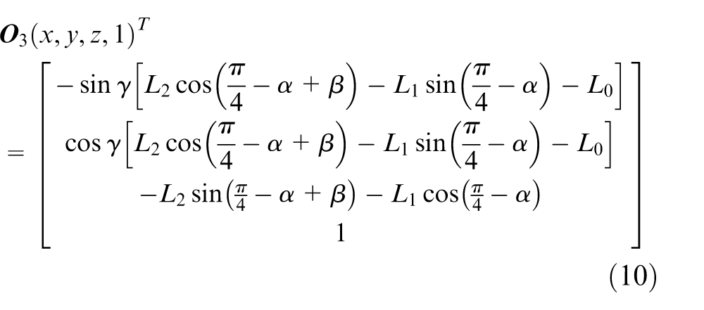
As shown in Figure 3, the position of O2 will be changed if bonnet tool in rotation about A-axis (z-axis in Figure 3), and then the position of bonnet tool in precession motion

where
So by equations (8) and (9)
So the position error of bonnet tool is
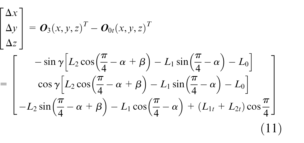
where Δx, Δy, and Δz are, respectively, the position error in x, y, and z direction; L1t and L2t are the theoretical lengths of swing arm A and B; L1 and L2 are the actual lengths of these two swing arms, α is the error angle of swing arm A, β is the error angle of swing arm B, and γ is the rotation angle of A-axis, for four-step tilted polishing, γ = 0°, 90°, 180°, and 270°, and for continuous polishing, γ = 0°–360°.
The position and size of polishing spot will change due to the change in the position of bonnet tool, and they are presented below
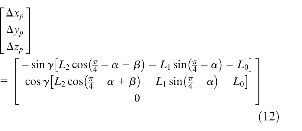
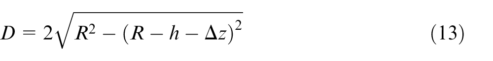
where R is the size of bonnet tool, h is Z-offset of bonnet tool, and Δz is the position error of bonnet tool in z direction.
From equations (12) and (13), the edge of polishing spot would be expressed as below
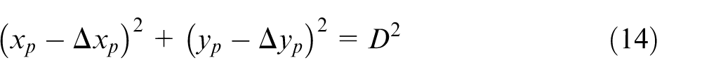
where xp and yp are the coordinates of the polishing spot edge on the workpiece. Because of the rotation of A-axis, Δxp, Δyp would be changed according to equation (12) and generate a certain amount of single polishing spots and then form four-step tilted polishing spot or continuous polishing spot.
Simulations
FEA for swing arm A and B
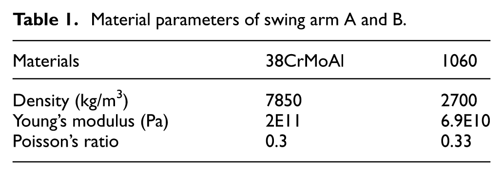
Static structural analysis for swing arm A and B in free condition and polishing status is carried out in ANSYS aiming to achieve the precession mechanism error in polishing process. Under free condition, only gravity of the mechanism exists, and polishing force is added in polishing status, as shown in Figure 4. The gravity of arm B is 336.39 N and that of spindle is 600 N. In polishing process, Z-offset of bonnet tool is 1 mm, inner pressure is 0.25 MPa, and the polishing force is 240 N. The materials of swing arm A and swing arm B are alloy steel (38CrMoAl) and aluminum alloy (1060 in Chinese Standard), respectively, and the material parameters are shown in Table 1. The analysis results have been demonstrated in Figures 5 and 6. The error parameters were achieved based on the maximum deformation of the two arms. They have been listed in Table 2. The result shows that the length of two swing arms and the composition angles of the mechanism changed both in free condition and polishing status and the angles changed significantly.
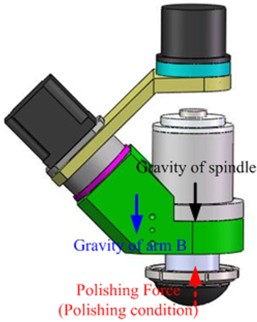
Forces of the mechanism under free and polishing conditions.
Material parameters of swing arm A and B.
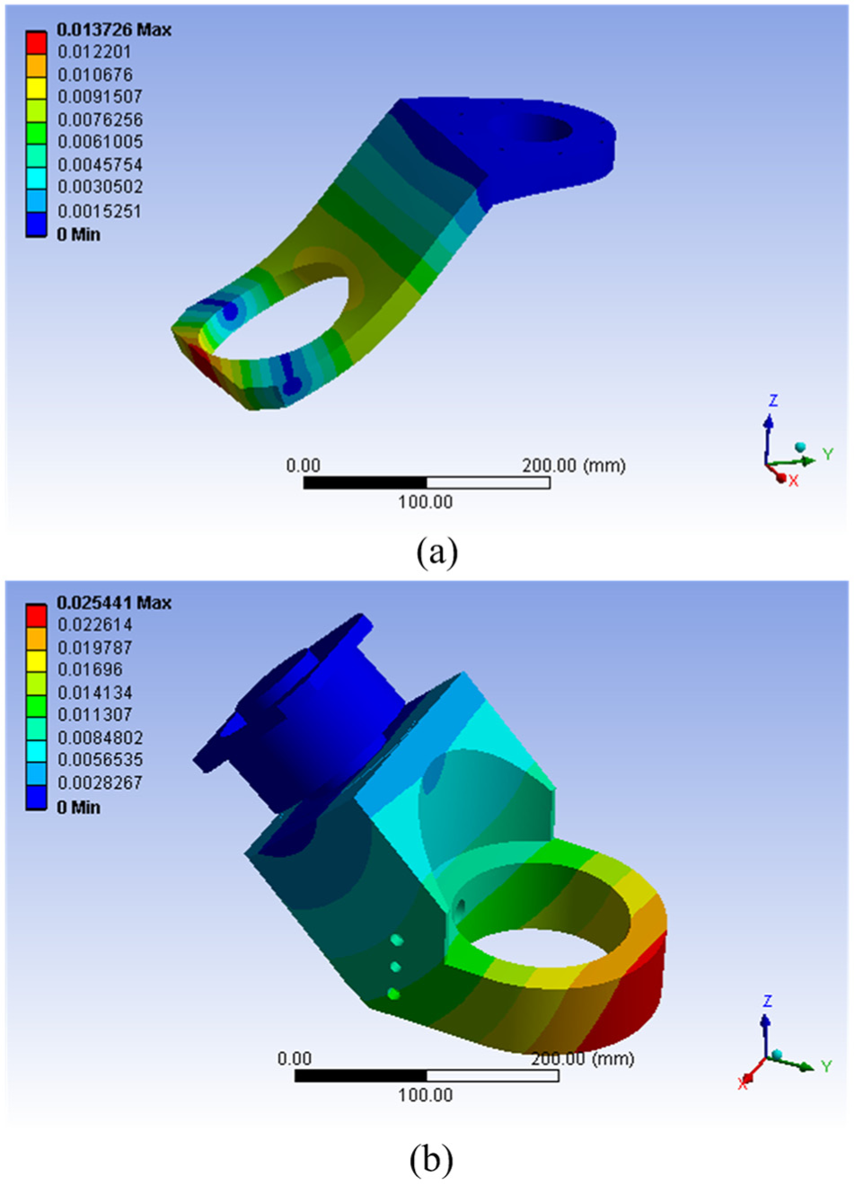
Analysis result of swing arm A and B in free condition: (a) deformation map of swing arm A and (b) deformation map of swing arm B.
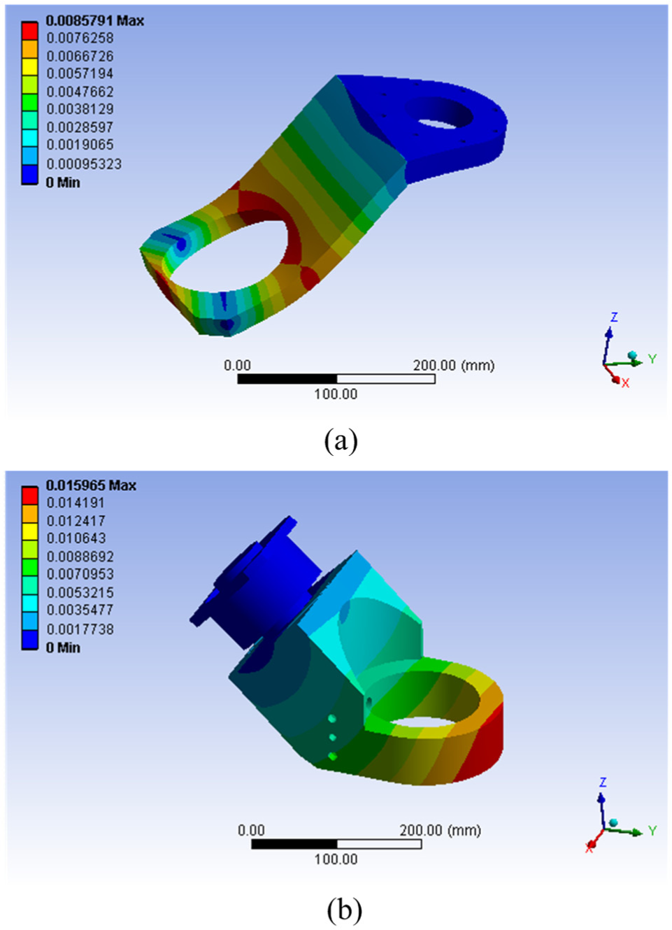
Analysis result of swing arm A and B in polishing status: (a) deformation map of swing arm A and (b) deformation map of swing arm B.
The error parameters of precession mechanism. a
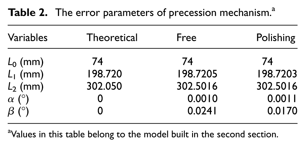
Values in this table belong to the model built in the second section.
Simulation for polishing spot
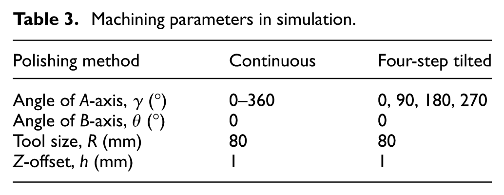
Based on the error model in second part of the article, the error parameters presented in Table 2 were used to simulate the centers of bonnet tool under free condition and polishing status in MATLAB to evaluate the effect of the mechanical errors on the position of bonnet tool, and then, polishing spots of four-step tilted polishing and continuous polishing were also simulated aiming to analyze the effect of precession mechanism error on polishing quality. The machining parameters in simulation are presented in Table 3. Figures 7 and 8 and Table 4 show the simulation results.
Machining parameters in simulation.
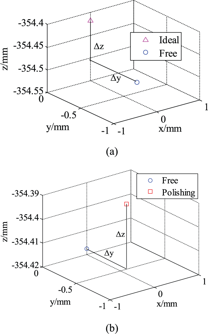
Position error of bonnet tool when rotation angle about A-axis (γ = 0): (a) free to ideal and (b) polishing to free.
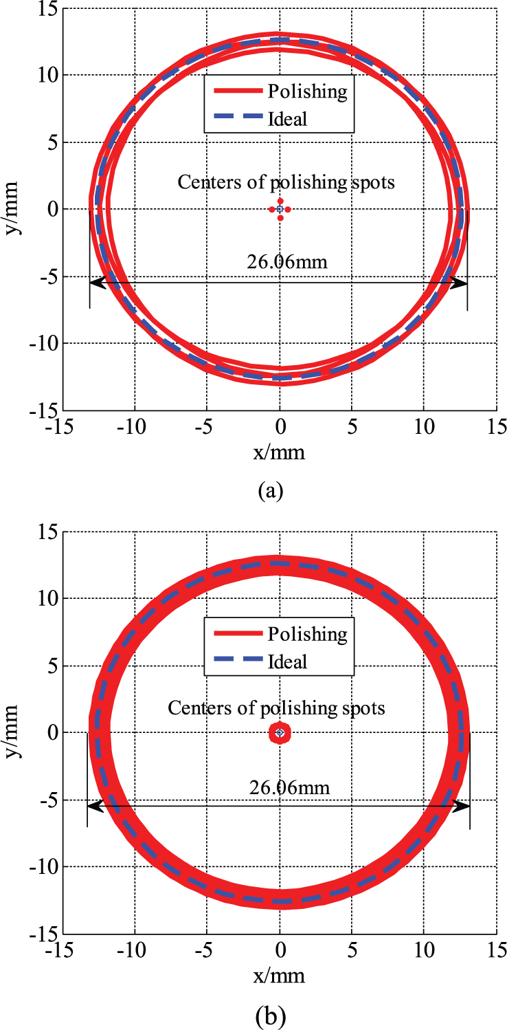
Shapes of polishing spots: (a) four-step tilted polishing spot and (b) continuous polishing spot.
Simulation result when rotation angle about A-axis (γ = 0).
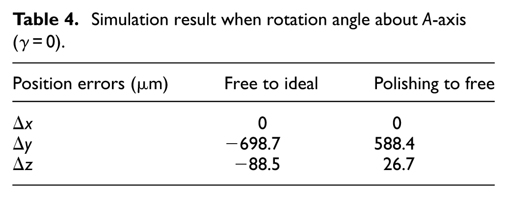
As shown in Figure 7 and Table 4, when γ = 0, position error of bonnet tool reaches −698.7 µm in y direction and −88.5 µm in z direction under free condition. While polishing, the error decreased 588.4 µm in y direction and 26.7 µm in z direction. As the position of bonnet tool is reset by the size of workpiece before polishing process, the polishing depth will reduce 26.7 µm according to the simulation results. From Table 3, the theoretical size of single-step polishing spot that can be derived is 25.219 mm by equation (13) where Δz = 0, while the simulation size is 24.88 mm under polishing status, the area has decreased 2.67% compared with the theoretical size.
From Figure 8(a) and (b), four-step tilted polishing spot consists of four superimposed single-step polishing spots in four × 90° steps, and continuous polishing spot consists of many single polishing spots in different angles ranging from 0° to 360°, compared with the ideal value, the area of four-step tilted polishing spot has increased 0.66% and that of continuous polishing spot has increased 6.78%. Compared with the increased value of single-step polishing spot, the eccentric value of bonnet tool is the main factor that affects the size and shape of polishing spot in two polishing methods, and it is necessary to compensate the eccentric error.
Experiments and discussion
Experiments have been conducted to test the simulation results, and the experimental prototype is shown in Figure 9. Both four-step tilted polishing spot and continuous polishing spot were generated on a BK7 part in this experiment. The machining parameters have been listed in Table 5. At last, QED SSI was used to measure the spot contour, and the results have been presented in Figure 10.
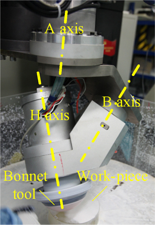
Experiment device.
Machining parameters.
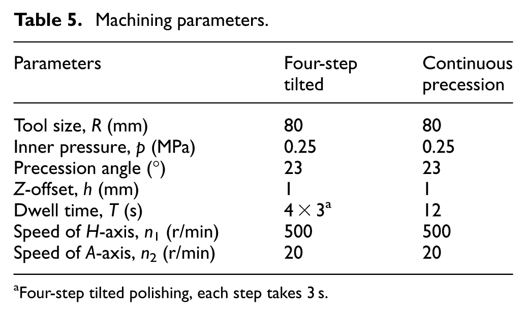
Four-step tilted polishing, each step takes 3 s.
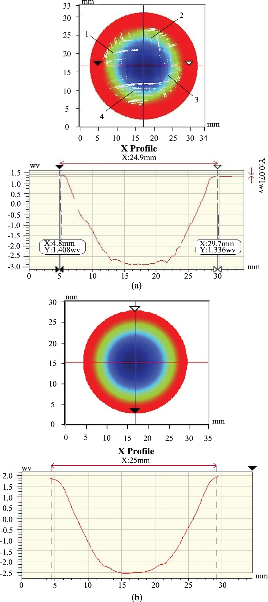
Removal function of workpiece: (a) four-step tilted polishing spot and (b) continuous polishing spot.
Figure 10 shows that four-step tilted polishing spot consists of four eccentric single-step polishing spots in four × 90° steps, and continuous polishing spot is uniform symmetric. The phenomenon is consistent with the simulation results presented in Figure 5. It indicates that the simulation analysis described in this article has some validity. From X profile of four-step tilted polishing spot and continuous polishing spot, the shape of removal function is not that good, especially for four-step tilted polishing. In Figure 8(a), four single-step polishing spots obviously have an eccentric value in x and y directions, combining with the simulation results above, the precession mechanism error mainly affects the position of polishing spot in x and y directions (eccentric value) and then make the size of polishing spot larger in precession motion.
To improve the polishing quality, the eccentric value must be reduced. In static structural analysis of swing arm A and B, it is found that bend is the main error of swing arm A, and for swing arm B, deformation is the main error. Therefore, when optimizing the mechanism, the bend of arm A and the deformation of arm B must be given priority. As to arm A, the stiffness of its material (38CrMoAl) is strong enough, and some additional supports need to be added, such as the increase in the material thickness and addition of some rods. For arm B, its material needs to be changed to the material with higher strength, lower density to reduce its deformation, and the load of swing arm A.
Figure 10 also shows that the size of four-step tilted polishing spot is 24.9 mm and that of continuous polishing spot is 25.0 mm. But they both are 26.06 mm in Figure 8(a) and (b), and there exists an error. The main reason is the deformation of bonnet tool is not considered in simulation in third part of this article, but the bonnet tool is inflated and it also has certain rigidity; it is difficult to compress the bonnet tool and the deformation of bonnet tool occurred not only on the contact area but also on the other region, together with the deformation of the mechanism, the Z-offset of bonnet tool does not reach the set value in machining process, so the polishing spots were reduced in size by equation (13). Furthermore, tool clamping error and mechanism processing error also have influences on the size of polishing spot. The effect of those errors needs further studies.
Conclusion
Precession mechanism has a deformation due to its gravity and polishing force in machining process, and the deformation has a great influence on the position of bonnet tool and then affects the polishing quality. In this article, it is found that the precession mechanism error mainly has an influence on the position of polishing spot in x and y directions and then make the size of polishing spot larger in precession motion. To improve the polishing quality, some additional supports need to be added on arm A, and the material of arm B needs to be changed to the material with higher strength and lower density. In addition, the size of polishing spot is also affected by the inflation pressure in bonnet tool, rigidity of bonnet tool, tool clamping error, and mechanism processing error and their specific impact mechanism needs to be studied further.
Footnotes
Appendix 1
Acknowledgements
The authors appreciate the invaluable expert comments and advices on the manuscript from all anonymous reviewers.
Declaration of conflicting interests
The author(s) declared no potential conflicts of interest with respect to the research, authorship, and/or publication of this article.
Funding
The author(s) disclosed receipt of the following financial support for the research, authorship, and/or publication of this article: This work was financially supported by major national science and technology projects (Grant No. 2013ZX04006011-206).